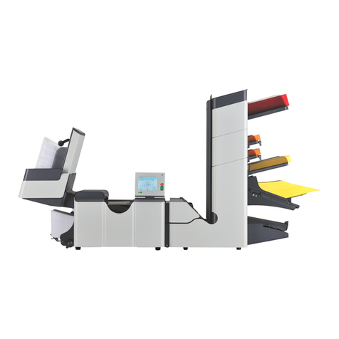
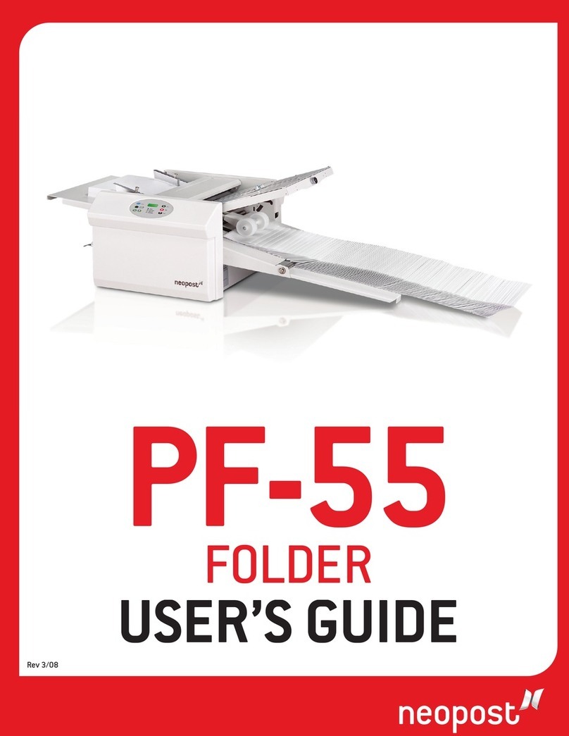
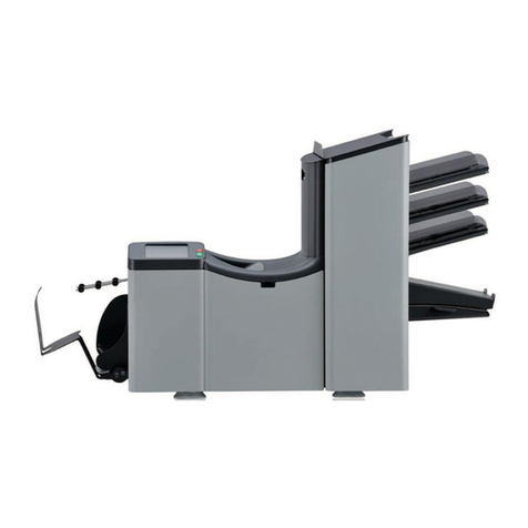
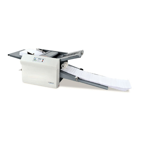
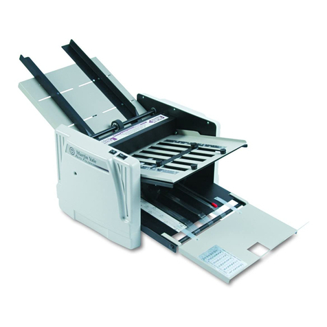
Neopost SI 72 User manual

1/33
SI 72
FOLD AND
INSERTING MACHINE
SI 72
OPERATOR MANUAL
Fig. 1
1. FUNCTION
The machine inserts documents into envelopes and then seals
and stacks the envelopes. Automatic monitoring ensures the
correct number of inserts per envelope.
The machine is equipped with a variety of special features as
document thickness detection, programmable jobs,
Load “N GoTM, FlexFeedTM, double feed control,
hopper swap, multifeed, daily mail, IntelliDeckTM and
PowerFoldTM.

Before using this machine thoroughly read the
operating instructions. In the European Union an
operator manual printed in the national
language(s), as well as an original operator manual
are supplied with the machine. If it is not, contact
your authorized distributor.
SI 722/33
SAFETY PRECAUTIONS
This machine is only to be operated by fully trained
personnel. The manufacturer accepts no responsibility
for injuries caused by unauthorized operation.
The opening of covers (except the top cover) must be
carried out only by a skilled and authorized person
who is aware of the hazard involved. The machine will
not operate with the top cover opened.
Keep long hair, fingers, jewellery, etc. away from
turning parts of the machine.
WARNINGS
If the feed/fold unit and inserter unit have to be
physically separated, the operator should taken into
account the heavy weight of the unit during separation.
Before connecting check whether the machine is
suitable for the local mains voltage; refer to the type
plate. The mains plug shall be connected only to a
socket outlet provided with a protective earth contact.
The socket outlet shall be installed near the equipment
and shall be easily accessible.
USED SYMBOLS
In this manual the following symbols are used.
Warning, this symbol indicates a wrong action
which can cause a hazard to health or
damage the machine.
Warning, this symbol indicates a hazard to life
because of high voltage.
NOTE
Additional information
Section Page
1. FUNCTION 1
2. GENERAL 3
2.1 Understanding the machine 3
2.2 Operating controls 4
2.3 Display buttons 5
3. PREPARATIONS 5
3.1 Moistening the brushes 5
4. OPERATING THE MACHINE 5
4.1 Switching on 5
4.2 The main menu 6
4.3 Job info screen 6
4.4 Other job menu 7
4.5 Adjustment of the document hopper 7
4.5.1 Document separation 7
4.5.2 Side guides 7
4.5.3 Filling the document hopper 8
4.6 Adjustment of the document stoppers 8
4.7 Feeding documents 9
4.8 Adjustment of the envelope feed 10
4.8.1 Envelope separation 10
4.8.2 Side guides 10
4.8.3 Envelope support 10
4.8.4 Envelope receiving tray 10
4.8.5 Envelope sealing 11
4.9 Test run menu 11
4.10 Insert position 11
4.11 Envelope insert fingers 11
4.12 Counters menu 12
4.13 Inserting menu 12
4.14 Load "N Go
TM
menu 12
4.15 Daily mail 13
4.16 Operator menu structure 14
5. JOBS 15
5.1 Job menu 15
5.2 Create job menu 15
5.3 Edit job menu 16
5.4 Copy job menu 16
5.5 Delete job menu 16
6. JOB SETTINGS 17
6.1 Envelope settings menu 17
6.1.1 Envelope with closed flap 17
6.1.2 Envelope with open flap 18
6.1.3 No envelopes 18
6.2 Document settings menu 18
6.2.1 Number of sheets 18
6.2.2 Document size 19
6.2.3 Hopper swap 19
6.2.4 Daily mail 20
6.3 Fold settings menu 20
6.3.1 No fold 20
6.3.2 Single fold 20
6.3.3 Letter fold 21
6.3.4 Zig-zag fold 21
6.3.5 Double parallel fold 21
6.4 Double document detection menu 22
6.4.1 Thickness detection measurement area 22
6.5 Job name menu 22
6.6 Job edit menu structure 23
7. FAULT FINDING 24
7.1 General 24
7.2 Clearing stoppages 24
7.3 Error codes 26
7.4 Operator troubleshooting 28
8. MAINTENANCE 30
8.1 Servicing 30
8.2 General cleaning 30
8.3 Cleaning the brushes 30
8.4 Cleaning the moistening felt 30
8.5 Cleaning the fold rollers 30
8.6 Cleaning the sensors 30
9. OPTIONS 31
10. SPECIFICATIONS 32
3/33SI 72
Fig. 2
FlexFeedTM; see 1
The FlexFeedTM is the feeding part of the system. There are
two types of feeders available. The automatic and the
special feeder. The automatic feeder does not require any
adjustments for the separation.
The FlexFeedTM can be equipped with double document
detection. In this way the system can detect faulty sets of
documents.
The FlexFeedTM can be equipped with hopper swap. This
means that two feeders can be linked as pairs. When the first
feeder is empty, the system switches to the other feeder.
Meanwhile the other empty feeder can be refilled without
stopping.
It’s also possible to feed multiple documents from one feeder.
In this way more documents of the same can be fed from one
station, for example an original and a copy of a document.
The automatic feeder can be equipped with a “daily mail”
function for processing documents or sets of documents
which cannot be processed automatically (e.g. stapled).
Collating area; see 2
After feeding, the documents are gathered in the collating
area.
IntelliDeckTM; see 3
The system can be equipped with the IntelliDeckTM.
Incorrect sets of documents automatically will be thrown out
by the IntelliDeckTM. In this way the system does not need to
stop. The correct sets will be transported to the PowerFoldTM
part.
PowerFoldTM; see 4
The PowerFoldTM part folds the documents. The following fold
types are possible:
•no fold.
•single fold.
•letter fold.
•zig-zag fold.
•double parallel fold.
Inserter; see 5
After folding the documents are transported to the inserter
unit where the documents are inserted into a waiting
envelope. The inserter then seals the envelope (or not) and
stacks them on the rear receiving tray. Automatic monitoring
ensures the correct number of inserts per envelope.
When a stoppage occurs, the system automatically signals
the operator and gives a suggestion about solving the
problem.
The system consists of the following parts:
FlexFeedTM.
collating area.
IntelliDeckTM.
PowerFoldTM.
inserter.
2. GENERAL
2.1 Understanding the machine
The SI 72 is a sophisticated fold and inserting system which
can process large quantities of mail rapidly and easily. The
system can be operated by means of a user friendly
interface.
The settings of the system (types of documents, type of
envelopes and the type of fold) is recorded in so called
jobs. These jobs can be programmed by an authorized
user.
As a special feature the system can be equipped with a
Load ‘N GoTM function. The purpose of this function is to go
to work as quick as possible without doing extensive
adjustments.
1
1
2
3
4
5
2
3
4
5

SI 724/33
S:side guides envelope hopper
T:envelopes support bracket
U:knob for separation adjustment
V:thumbwheel for side guide adjustment
2.2 Operating controls
A:envelope receiving tray
B:envelope slide
C:loc
D:locking handle loc
E:control panel
F:vertical transport (opened)
G:vertical transport hand grip
H:document feed tray
I:collator arm
J:collator area
K:PowerFoldTM cover (opened)
L:locking handle PowerFoldTM
M:power inlet, power switch and fuse
N:handle for clearing stoppages
O:handle for clearing stoppages
P:water tray
Q:bellow
R:side cover (opened)
Fig. 3 Fig. 4
AB C D E
G
F
HIJLMNOP
QR KJUS V S

5/33SI 72
2.3 Display buttons
The keys below the display are used for the functions:
“start”, “stop”, “clear” and “esc” (see fig. 5).
The 6 keys on the right of the display are used for the
corresponding functions shown in the display.
When the start key is pressed the machine starts
processing.
After pressing the stop key the machine stops after
completing the document set.
When the clear key is pressed the machine stops feeding.
The machine will empty and stops when ready. It is
possible that there are still documents left in the document
feeder (for example a small card). Remove all these
documents from the feeder before restarting. See also 7.2
Clearing stoppages on page 24.
The escape key can be used to exit a menu without saving
any (altered) settings.
Fig. 5
3. PREPARATIONS
3.1 Moistening the brushes
The water tray A must always be filled with water and the
brushes must be moistened. An extra set of brushes is
provided so that one set can be soaked in water whilst the
other set is used. For this a special section is available in
the water tray. In that way there is always one set ready for
usage.
To fill the water tray, lift the locking handle B (fig. 6) of the
loc. Then pull up the loc into the vertical position. Open the
side cover R (fig. 3 on page 4 ) and fill the water tray to
the “max” level.
Before moving the machine, the watertray
must be empty.
Fig. 6
4. OPERATING THE MACHINE
4.1 Switching on
The machine can be switched on or off with the power
switch A (fig. 7 ). After starting up, the display shows the
“main menu (1)” (see fig. 8 on page 6).
For operating the machine the following steps have to be
taken (also see page 14 for a schematic view):
•check the job by means of the “job info” screen,
•when needed, select another job in the “other job”
menu,
•when needed, make adjustments to the document
hopper,
•when needed, make adjustments to the envelope feed,
•when needed, adjust the document stopper position,
•when needed, adjust the insert position,
•when needed, adjust the envelope insert fingers,
•make a test run to check all settings,
•if desired set the counters in the “counters” menu.
When the system is equipped with the Load “N GoTM
function this can be used to create a new simple job
(see page 12).
Fig. 7
A B A
Key

SI 726/33
4.2 The main menu
The main menu consists of two menus, “main menu (1)”
and “main menu (2)”. After pressing key 6 in the
“main menu (1)”, the display will show the
“main menu (2)”, as shown in fig. 9.
The “main menu (1)” shows 6 different functions:
•job information (key 1), press key 6 to go back to the
“main menu (1)” (the job information function is
available in all the menus where the symbol is
shown),
•go to the “other job” menu (key 2),
•go to the “test run” menu (key 3),
•go to the “counters” menu (key 4),
•go to the “Load “N GoTM “menu (key 5) (only available
if the machine is equipped with the IntelliDeckTM),
•go to the “main menu (2)” (key 6).
Fig. 8
The “main menu (2)”, as shown in fig. 9 shows 5 different
functions:
•job information (key 1),
•display contrast lighter (key 2),
•display contrast darker (key 3),
•go to the “job menu” (key 4) (only for authorized
personnel),
•back to the “main menu (1)” (key 6).
Fig. 9
4.3 Job info screen
When key 1 is pressed in a menu, the “job info” screen
will be displayed. Press key 6 to go back to the
“main menu (1)”.
The “job info” screen shows the following job settings:
•inserting of the envelopes:
- envelope with closed flap ( ),
- envelope with open flap ( ),
- no envelopes ( ),
•document thickness detection on or off ( ),
•which feeders are selected ( black is selected),
•which feeders are linked ( hopper swap),
•the feedstation’s double feed control are on ( ),
•thelength of the document in the feeder ( ),
•daily mail “on “or “off” ( ).
Fig. 10
Key Key Key

7/33SI 72
4.4 Other job menu
After pressing key 2 in the “main menu (1)”, the display
shows the “other job” menu (see fig. 11). The
“other job” menu shows the following functions:
•job information (key 1) (see section 4.3),
•select a higher job number (key 3),
•select a lower job number (key 4),
•select the desired job and confirm with “OK” (key 6)
which will get you back to the “main menu (1)”.
Only programmed jobs can be selected (maximum of 9
jobs).
Fig. 11
4.5 ADJUSTMENT OF THE DOCUMENT HOPPER
4.5.1 Document separation
The document separation for the automatic feeders is set
automatically. There are no manual adjustments needed.
The document separation for special feeders must be
adjusted manually as follows:
•push the knob A (fig. 12) forward until it clicks,
•open the left side guide B (fig. 12) by turning it
downwards,
•place a document on the feeding tray and slide it about
60 mm (2.4 inch) into the machine (turn the knob A
counter clockwise if the separation is set to narrow),
•push the document between the rollers,
•turn the knob A clockwise to get more resistance or
counter clockwise to lower the resistance.
The separation is adjusted correctly when a slight
resistance is felt on the document.
Pull the knob A (fig. 12) back again when ready. Close the
left side guide upwards.
Fig. 12
4.5.2 Side guides
To adjust the side guides it is best to remove the document
feeding tray from the feeder as follows:
•push handle A (fig. 13) downwards,
•lift the document feeding tray upwards to unhook it and
then pull it out from the feeder,
(Continued on the next page).
Fig. 13
B A A
Key

SI 728/33
•loosen the knob B half a turn (fig. 14),
•grab the side guides in the middle and push them apart
as far as possible,
•put a small stack of documents between the side guides.
•grab the side guides in the middle and push them
towards the documents,
The space between the side guides and the documents
should be such that the documents have just enough
play to move freely,
•re-tighten knob B,
•remove the stack of documents.
Replace the document feeding tray as follows:
•place the document feeding tray under guide A (as
shown in fig.15),
•push the document feeding tray up and then lower it
into position.
Fig. 14
4.5.3 Filling the document hopper
Open the left side guide B (fig.12) by turning it
downwards. The feed rollers will automatically be lifted.
Place a stack of documents between the side guides. Turn
the left side guide upwards again.
Feed the documents (depending on the type of documents
and the type of fold) as shown in 4.7 Feeding documents
page 9.
Fig. 15
4.6 Adjustment of the document stoppers
The position of the document stoppers can be adjusted
according to the longest document used (the document size
is programmed in jobs).
Initially the document stoppers are set to position B. In this
position a wide variety of documents can be handled and
adjustment is not needed.
To adjust the stopper position lift and hold the collator arm
D, squeeze the stopper and pull the front side tab up. To
replace the stopper first place the flat back tab into the
slotted hole and then push the stopper into position.
For use of small documents of about 148,5 mm
(5.8 inch) or smaller, the four document stoppers must be
set in the first position (position A).
For use of longer documents, maximal 356 mm (14 inch),
the four document stoppers must be set in last position
(position C).
The position of the document stoppers is set by service
personnel according to the document sizes programmed in
the jobs.
Fig. 16
A A B C
D

9/33SI 72
4.7 Feeding documents
Type of documents
one document hopper swap two documents document + enclosure
Fold type
no fold single fold
letter fold double
parallel fold
Address carrier in top feeder.
Face up and leading
Address carrier in top linked
pair feeders.
Face up and leading.
Address carrier in top feeder.
Face up and leading
Address carrier in top feeder.
Face up and leading
zig-zag fold
Address carrier in bottom feeder.
Face down and trailing
Address carrier in bottom linked
pair feeders.
Face down and trailing
Address carrier in bottom feeder.
Face down and trailing
Address carrier in top feeder.
Face down and trailing

SI 7210/33
Adjust the envelope separation by turning knob D counter
clockwise until two envelopes (flap down and trailing), one
on top of the other, can be moved backwards and forwards
between the rollers without resistance.
The turn knob D clockwise until one envelope will pass
between the rollers.
After starting the machine it may occur that more than one
envelope at a time is pulled in. If this happens, rotate knob
D clockwise a quarter turn. Repeat if necessary to obtain
correct operation.
Once the envelope separation has been set, a wide variety
of envelopes can be handled.
4.8 Adjustment of the envelope feed
4.8.1 Envelope separation
Fig. 17
4.8.2 Side guides
Take a stack of about 20 envelopes. Fan the envelopes a
bit (see fig. 18) and place the envelopes in the hopper with
the flap down and “trailing” on the envelope support B
(fig.17).
The bottom envelope must enter the separator first. Adjust
the side guides C (fig.17) by turning the thumbwheel A
(fig.17) to provide enough space to move freely. Too much
play causes skewing.
4.8.3 Envelope support
Adjust the envelope support B (fig.17) so that the flap side
of the envelope is lifted about 20 mm (0.8 inch).
Envelopes may skew on the insert table. The envelope
support B can be rotated slightly to compensate this. Turn
the envelope support B so that the weight of the envelopes
is distributed evenly on both sides.
Top up the envelope hopper with more envelopes.
Fig. 18
4.8.4 Envelope receiving tray
The SI 72 has a rear envelope receiving tray A (see fig.19)
this can be adjusted according to the envelope height, by
shifting it in or out.
Fig. 19
C D B A C A

11/33SI 72
4.8.5 Envelope sealing
To turn sealing on or off, lift the locking lever of the loc (D
of fig.3, page 4) and pull the loc into the vertical position.
Shift the blue handle A (fig. 20) towards to set sealing off
.
Shift the handle towards to set sealing on. Push the loc
down until it locks.
Fig. 20
4.9 Test run menu
Press key 3 in the “main menu (1)” to enter the “test run”
menu (fig. 21). The “test run” menu shows the following
functions:
•feed one envelope onto the insert table (key 1),
•make one insert (key 2),
•set the insert position (= envelop stop position) to the
right (key 4),
•set the insert position to the left (key 5),
•save the insert position setting with “OK” (key 6) which
will get you to the “main menu (1)”.
First the insert position must be set. Then the insert fingers
must be adjusted. To check all settings a test run can be
made.
4.10 Insert position
Press key 1 in the “test run” menu to bring one envelope
onto the insert table. Lift the locking lever of the loc and pull
the loc into the vertical position.
The flap folding line must be positioned under the green
indicator A (fig. 22). If necessary adjust the flap folding
line position by pressing key 4 or 5 in the “test run” menu.
Each key stroke stops the next envelope 0,5 mm (0.02
Fig. 21
inch) to the right (earlier) or to the left (later). Check the
settings by pressing key 1 again.
4.11 Envelope insert fingers
To adjust the insert fingers B (fig. 22) (5 in total) loosen the
knurled knob C (fig. 22) on top of each finger.
Then adjust each finger so that the tip enters about
5 mm (0.2 inch) into the envelope. Re-tighten the knurled
knob. The fingers on either side of the loc can be moved
sideways to the desired position. Place the outer fingers
about 10 mm (0.4 inch) from the edges of the envelope.
The middle finger cannot be moved sideways.
Check the position of the insert fingers when changing to
a different type of envelope.
When adjusting the fingers sideways, be sure that finger
D (fig. 22) is not positioned over sensor E
(fig. 22). When an incorrect finger position is adjusted the
display shows an “error screen” see page 23).
Fig. 22
A A CBED
Key

SI 7212/33
4.12 Counters menu
After pressing key 4 in the “main menu (1)”, the display
shows the “counters” menu (fig. 23). The “counters” menu
shows the following functions:
•reset the daily counter and stopcounter to zero (key 2),
•decrease the preset counter (key 3),
•increase the preset counter (key 4),
•save the counter settings with “OK” (key 6) which will
get you back to the “main menu (1)”.
The stopcounter is switched off when it is set to zero. The
display will show “Stop at off”.
The stopcounter can be set between 0 (switched off) and
9999.
Fig. 23
4.13 Inserting menu
When the start key is pressed the machine starts inserting
in automatic mode. The display shows the “inserting” menu
(fig. 24).
Press key 1 in the “inserting” menu for job information.
Return to the “inserting” menu by pressing key 6.
Fig. 24
4.14 Load "N GoTM menu
When the system is equipped with the Load “N GoTM
function this will be displayed in the “main menu (1)” After
pressing key 5 in the “main menu (1)”, the
“Load “N GoTM” menu is displayed (fig. 25).
The Load "N GoTM function can be used for creating simple
jobs. The machine automatically recognizes the document
size, envelope size and necessary fold settings.
The adjustment of the envelope feed must be made to
obtain correct operation (see page 10).
When special feeders are selected the adjustment of the
document hoppers must be made (see pages 7 through 8).
The document will be folded and inserted in the envelope.
Only the address position can be adjusted if needed.
Testset run
Press key 3 to start a testset run (fig. 25). The machine
prepares a job 0 which is named “Load "N GoTM”.
Only the feeders that feed successfully will be selected.
When feeders are fitted with the double feed control
option, this will be selected automatically.
Fig. 25
Key Key Key

13/33SI 72
To try again, start again from the “main menu (1)”.
After a testset run the display shows the “Load “N GoTM”
menu (fig. 26) again, extended with the possibility of
adjusting the address position. If needed adjust the address
position as follows:
•press key 4 to set the address higher. Each key stroke
brings the address up 1 mm (0.04 inch) (maximum 10
mm (0.4 inch) higher),
•press key 5 to set the address lower. Each key stroke
brings the address down 1 mm (0.04 inch) (maximum
10 mm (0.4 inch) lower).
If the required address position is beyond the maximum
range of 10 mm (0.4 inch) up and 10 mm (0.4 inch)
down, the Load “N GoTM function can not be used. Use a
programmed job instead.
Fig. 26
Press key 1 (fig. 26) in the “Load “N GoTM” menu for the
“Load "N Go help” advice. This screen gives suggestions
for the Load “N GoTM usage. Press key 6 to return to the
“Load “N GoTM” menu.
In the Load "N GoTM job the following options cannot be
used:
•hopper swap (the machine switches automatically to the
upper hopper when the lower hopper is empty and vice
versa),
•multifeed (more sheets are fed from the same hopper
into the envelope).
The usage of the Load “N GoTM function is not possible in
the no envelopes mode, or with usage of envelopes with
open flap.
The Load “N GoTM job can not be saved.
When the machine is switched off the settings will be lost.
Fig. 27
4.15 Daily mail
For processing documents or sets of documents which can
not be processed automatically (e.g. stapled documents)
the daily mail function can be used.
The automatic (upper) feeder can be equipped with a daily
mail switch. Contact your dealer when further information
is wanted.
Switch to daily mail in the following way:
•turn the left side guide A downwards (fig. 28),
•the daily mail handle B will be visible and can be set.
Push the handle to the right to switch to the daily mail
function. Push the handle to the left to switch back to the
automatic function,
•turn the left side guide upwards again.
Be sure the daily mail function is switched off when
switching to normal use again.
Fig. 28
A
B
Key Key

SI 7214/33
4.16 Operator menu structure
Start key
Start processing
Stop key
Stop processing after completing
the set
Clear key
Empty the system and stop
Escape key
Exit a menu without saving any
altered settings
separation, page 7
side guides, page 7
filling the hopper page 8
document stoppers, page 8
separation, page 10
side guides, page 10
envelope support, page 10
receiving tray, page 10
envelope sealing page 11
Mechanical adjustments
Job info, page 6
Adjust contrast, page 6
Enter job menu, page 6
To main menu (1)
Job info, page 6
Select higher job number, page 7
Select lower job number, page 7
Confirm settings
Key
Feed one evelope, page 11
Insert one document, page 11
Stop position to the right, page 11
Stop position to the left, page 11
Confirm settings
Reset counters, page 12
Higher stop counter, page 12
Lower stop counter, page 12
Confirm settings
Load "N GoTM help page 13
Testset run, page 12

15/33SI 72
5. JOBS
For an overview of the complete “create” or “edit job”
menu structure, see page 23.
5.1 Job menu
After pressing key 4 in the “main menu (2)”
(fig. 9 on page 6), the display shows the “job access”
screen and asks for a pin code to enter (fig. 29).
Enter the pin code with the keys 1 through 6.
When the wrong pin code is entered, the cursor is set to
the first number to try again.
After 3 times entering the wrong pin code the display
shows the “main menu (2)” again.
Fig. 29
When a correct pin code is entered, the display shows the
“job menu” as shown in fig. 30. The “job menu” shows the
following functions:
•job information (key 1),
•create a job (key 2),
•edit a job (key 3),
•copy a job (key 4),
•delete a job (key 5),
•exit and go back to the “main menu (2)” (key 6).
The escape key will get you back to the previous menu.
Fig. 30
5.2 Create job menu
After pressing key 2 in the “job menu” the display will
show the “create job” menu as shown in fig. 31. If all jobs
are programmed the display shows “No more free jobs”.
The “create job” menu shows the following functions:
•choose a higher free job number (key 3),
•choose a lower free job number (key 4),
The display will start with the lowest free job number
available. Job numbers already programmed or job
numbers locked by service personnel will not be shown.
•select the desired job and confirm with “OK” (key 6)
which will get you to the “job settings” menu. All job
settings are described in chapter 6, starting on page
17.
A new selected job number starts with default settings.
Fig. 31
Key Key Key

SI 7216/33
5.3 Edit job menu
When key 3 in the “job menu” is pressed, the display
shows the “edit job” menu as shown in fig. 32. The initially
selected job will be displayed. The “edit job” menu shows
the following functions:
•Job information (key 1),
•choose a higher job number to edit (key 3),
•choose a lower job number to edit (key 4),
•select the job to edit and confirm with “OK” (key 6)
which will get you to the “job settings” menu. All job
settings are described in chapter 6, starting on page
16.
Fig. 32
5.4 Copy job menu
After pressing key 4 in the “job menu”, the display shows
the “copy job” menu as shown in fig. 33.
The “copy job” menu shows the following functions:
•job information (key 1),
•choose a higher job number to copy from (key 2),
•choose a lower job number to copy from (key 3),
•choose a higher job number to copy to (key 4),
•choose a lower job number to copy to (key 5),
•copy the job with “OK” (key 6) which will get you to the
“job menu”.
If all jobs are programmed the display shows “No more
free jobs”.
Fig. 33
5.5 Delete job menu
After pressing key 5 in the “job menu”, the display shows
the “delete job” menu, as shown in fig. 34.
The “delete job” menu shows the following functions:
•job information (key 1),
•select a higher job number to delete (key 3),
•select a lower job number to delete (key 4),
•delete job with “OK” (key 6) which will get you to the
“job menu”.
Fig. 34
Key Key Key

17/33SI 72
6 JOB SETTINGS
After confirmation (key 6) in the “create job” or
“edit job” menu, the display shows the “job settings” menu
as shown in fig. 35. The “job settings” menu shows the
following functions:
•select a setting menu by pressing key 1 or 2,
To program a job use the following order of settings:
1. Envelope settings menu ( )
2. Document settings menu ( )
3. Fold settings menu ( )
4. Double document detection (DFC) settings menu ( )
•select the chosen settings menu to edit (key 3),
•go to the “job name” menu (key 5),
•save the job settings by pressing key 6 which will
automatically get you back to the “job menu”.
Fig. 35
6.1 Envelope settings menu
When the “envelope settings” menu is selected and
confirmed in the “job settings” menu, the display shows the
screen as shown in fig. 36. In this menu, the following
choices are available by pressing key 1:
1. Envelope with closed flap ( )
2. Envelope with open flap ( )
3. No envelopes ( )
6.1.1 Envelope with closed flap
When “envelope with closed flap” is selected the display
shows the screen as shown in fig. 36. The following
choices are available:
•go to the envelope with open flap screen (key 1),
•increase the envelope height (key 2),
•decrease the envelope height (key 3),
•confirm the setting by pressing “OK” (key 6) which will
get you back to the “job settings” menu.
The envelope height can be set between 90 mm
(3.5 inch) and 162 mm (6.38 inch).
Default the envelope size is set to 162 mm (6.38 inch).
Fig. 36
Key Key

SI 7218/33
6.1.2 Envelope with open flap
When “envelope with open flap” is selected the display
shows the screen as shown in fig. 37. The following
choices are available:
•go to no envelopes screen (key 1),
•increase the envelope height (key 2),
•decrease the envelope height (key 3),
•increase the flap height (key 4),
•decrease the flap height (key 5),
•confirm the settings by pressing “OK” (key 6) which
will get you back to the “job settings” menu.
The envelope height can be set between 90 mm
(3.54 inch) and 162 mm (6.38 inch).
The flap height can be set between 32 mm and the
envelope height minus 32 mm (1.26 inch).
Default the envelope height is set to 162 mm
(6.38 inch) and the envelope flap size is set to 44 mm
(1.73 inch).
Fig. 37
6.1.3 No envelopes
When “no envelopes” is selected, the display shows the
screen as shown in fig. 38. The following choices are
available:
•go to the envelope with closed flap screen (key 1),
•confirm the settings by pressing “OK” (key 6) which
will get you back to the “job settings” menu.
Fig. 38
6.2 Document settings menu
When the “document settings” menu is selected and
confirmed (key 6) in the “job settings” menu, the display
shows the screen as shown in fig. 39.
The following choices are available, by pressing key 1:
1. set number of documents ( )
2. set document size ( )
3. set hopper swap ( )
4. set daily mail on or off ( )
6.2.1 Number of sheets
When number of sheets is selected the following choices
are available (see fig. 39):
•go to document size screen (key 1),
•select a higher feeder number (key 2) (The lowermost
feeder is feeder number one),
•select a lower feeder number (key 3),
•increase the number of documents of the selected
feeder (key 4),
•decrease the number of documents of the selected
feeder (key 5),
•confirm the settings by pressing “OK” (key 6) which
will get you back to the “job settings” menu.
Fig. 39
Key Key Key

19/33SI 72
When the system is equipped with the IntelliDeckTM option,
the number of documents can be set between 0 and 9.
If the IntelliDeckTM option is not available the number of
documents can be set to 0 or 1.
A feeder can be deselected when the amount of documents
is set to zero.
The default setting is 1 document per feeder.
When a feeder is set to daily mail the number of
documents is always 1 and can not be set in this screen.
6.2.2 Document size
When document size is selected, the display shows the
screen as shown in fig. 40. The following choices are
available:
•go to the hopper swap screen (key 1),
•select a higher feeder number (key 2),
•select a lower feeder number (key 3),
•increase the document size of the documents in the
selected feeder (key 4),
•decrease the document size of the documents in the
selected feeder (key 5),
•confirm the settings by pressing (key 6) which will get
you back to the “job settings” menu.
The document size can be set between 90 mm
(3.54 inch) and 356 mm (14 inch) in steps of 1 mm (0.04
inch).
The default document size setting of a new job is 297 mm
(11.7 inch).
The position of the document stoppers is set by service
personnel according to the document sizes programmed in
the jobs.
Fig. 40
6.2.3 Hopper swap
When hopper swap is selected, the display shows the
screen as shown in fig. 41. The following choices are
available:
•go to the daily mail screen or when this is not available
to the “number of sheets” screen (key 1),
•select the pair of feeders which must be linked (key 2 or
3),
•select linked or unlinked for a pair of feeders (key 4),
•confirm the settings by pressing “OK” (key 6) which
will get you back to the “job settings” menu.
When a pair of feeders is linked, the settings of the
lowermost feeder will be shown in the display.
Fig. 41
Key Key

SI 7220/33
6.2.4 Daily mail
When daily mail is selected, the display shows the screen
as shown in fig. 42. The following choices are available:
•go to the “number of sheets” screen (key 1),
•set the daily mail function on or off (key 3),
•confirm the settings by pressing “OK” (key 6) which will
get you back to the “job settings” menu.
Fig. 42
6.3 Fold settings menu
When the “fold settings” menu is selected and confirmed
with “OK” (key 6) in the “job settings” menu, the display
shows the screen as shown in fig. 43. In this menu, the
following choices are available by pressing key 1:
1. No fold ( )
2. Single fold ( )
3. Letter fold ( )
4. Zig-zag fold ( )
6.3.1 No fold
When no fold is selected, the display shows the screen as
shown in fig. 43. The following choices are available:
•go to the “single fold” menu (key 1),
•select settings by pressing “OK” (key 6) which will get
you back to the “job settings” menu.
Fig. 43
6.3.2 Single fold
When single fold is selected, the display shows the screen
as shown in fig. 44. The following choices are available:
•go to the “letter fold” menu (key 1),
•increase the fold position to the right (key 3),
•decrease the fold position to the left (key 4),
•confirm the settings by pressing “OK” (key 6) which
will get you back to the “job settings” menu.
The fold length can be minimally 75 mm (2.9 inch) and
maximally 25 mm (0.10 inch) less then the length of the
longest document used.
Fig. 44
Key Key Key
Table of contents
Other Neopost Folding Machine manuals