Xycom 1510 User manual

1510
Industrial PC
Computer System
Ó
ÓÓ
Ó2001 XYCOM AUTOMATION, INC. Printed in the United States of America


Revision Record
3
Revision Description Date
A Manual Released 02/01
B Update notes/UL 04/01
Xycom Automation Part Number 140412
Trademark Information
Brand or product names are registered trademarks of their respective owners.
Windows is a registered trademark of Microsoft Corp. in the United States and other countries.
Copyright Information
This document is copyrighted by Xycom Incorporated (Xycom) and shall not be reproduced or
copied without expressed written authorization from Xycom.
The information contained within this document is subject to change without notice. Xycom
does not guarantee the accuracy of the information and makes no commitment toward keeping
it up to date.
United States FCC Part 15, Subpart B, Class A EMI Compliance Statement:
NOTE: This equipment has been tested and found to comply with the limits for a Class A digital
device, pursuant to part 15 of the FCC Rules. These limits are designed to provide reasonable
protection against harmful interference when the equipment is operated in a commercial envi-
ronment. This equipment generates, uses, and can radiate radio frequency energy and, if not
installed and used in accordance with the instruction manual, may cause harmful interference to
radio communications. Operation of this equipment in a residential area is likely to cause harmful
interference in which case the user will be required to correct the interference at his own expense.
For European Users:
WARNING
This is a Class A product. In a domestic environment, this product may cause radio interference
in which case the user may be required to take adequate measures.
INSTALLATION: Electromagnetic Compatibility WARNING
The connection of non-shielded equipment interface cables to this equipment will
invalidate FCC EMI and European Union EMC compliance and may result in
electromagnetic interference and/or susceptibility levels which are in violation of
regulations which apply to the legal operation of this device. It is the responsibil-
ity of the system integrator and/or user to apply the following directions which
relate to installation and configuration:
1. All interface cables must include shielded cables. Braid/foil type shields are recommended.
Communication cable connectors must be metal, ideally zinc die-cast backshell types, and
provide 360 degree protection about the interface wires. The cable shield braid must be
terminated directly to the metal connector shell, ground drain wires alone are not adequate.
2. Protective measures for power and interface cables as described within this manual must
be applied. Do not leave cables connected to unused interfaces or disconnected at one end.

1510 Industrial PC Computer System Manual
4
Changes or modifications to this device not expressly approved by the manufacturer could
void the user’s authority to operate the equipment.
3. EMC compliance is, in part, a function of PCB design. Third party add-on AT/XT peripheral
PCB assemblies installed within this apparatus may void EMC compliance. FCC/CE compli-
ant PCB assemblies should always be used where possible. XYCOM can accept no re-
sponsibility for the EMC performance of this apparatus after system integrator/user installa-
tion of PCB assemblies not manufactured and/or expressly tested and approved for compli-
ance by XYCOM. It is the responsibility of the system integrator/user to ensure that installa-
tion and operation of such devices does not void EMC compliance

Table of Contents
5
Table of Contents
Product Overview ..................................................................................................................................................... 7
Standard Features...................................................................................................................................................... 7
Optional Features...................................................................................................................................................... 8
Processors .............................................................................................................................................................. 8
SDRAM ................................................................................................................................................................. 8
Operating Systems ................................................................................................................................................. 8
Power On Management Configuration...................................................................................................................... 8
Unpacking the System ............................................................................................................................................ 11
Quick Start-up......................................................................................................................................................... 11
Preparing for the Tests............................................................................................................................................ 13
Running the Tests ................................................................................................................................................... 15
System Components................................................................................................................................................ 17
Internal View .......................................................................................................................................................... 17
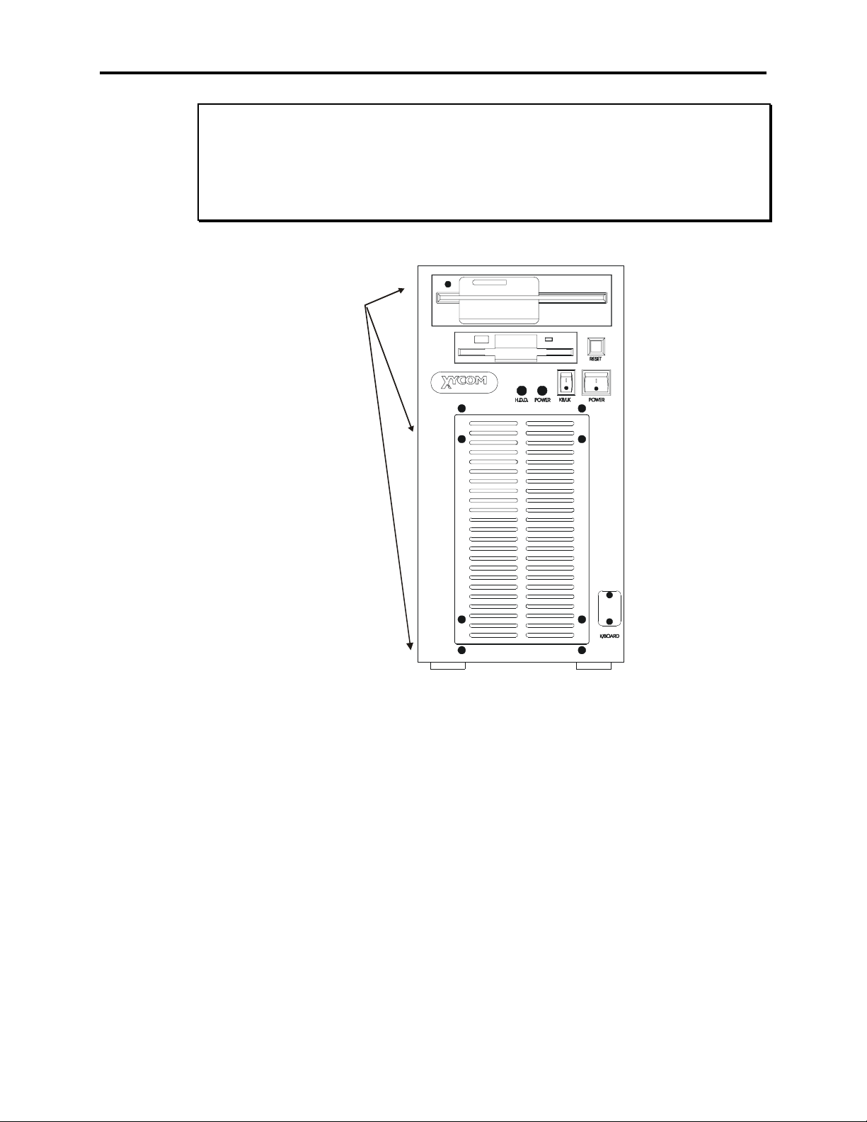
Front View .............................................................................................................................................................. 18
Back View .............................................................................................................................................................. 19
PS/2 keyboard and mouse connector ...................................................................................................................... 20
Installing Options.................................................................................................................................................... 20
Internal Hardware Options...................................................................................................................................... 20
DRAM and Additional DRAM Single In-Line Memory Modules (SIMMs) ....................................................... 21
ISA or PCI Boards ............................................................................................................................................... 21
Reinstalling Operating Systems .............................................................................................................................. 22
MS-DOSÒreinstallation ........................................................................................................................................ 22
WindowsÒ95 reinstallation ................................................................................................................................... 23
WindowsÒNT reinstallation.................................................................................................................................. 23
Installing Drivers .................................................................................................................................................... 24
Ethernet Drivers...................................................................................................................................................... 24
Video Drivers ......................................................................................................................................................... 24
CD-ROM Drivers ................................................................................................................................................... 25
Miscellaneous Drivers ............................................................................................................................................ 25
Mounting Considerations........................................................................................................................................ 25
Enclosures............................................................................................................................................................... 26
System Power ......................................................................................................................................................... 26
Excessive Heat........................................................................................................................................................ 27
Electrical Noise....................................................................................................................................................... 27
Line Voltage Variation ........................................................................................................................................... 27
Mounting Dimensions............................................................................................................................................. 28
Mounting Brackets and Mounting Dimensions Vertical Mount ............................................................................. 28
Mounting Brackets and Mounting Dimensions Horizontal Mount ......................................................................... 29
Mounting the Unit................................................................................................................................................... 30
Safety Agency Approval......................................................................................................................................... 31
Preventive Maintenance.......................................................................................................................................... 33
Fuse Replacement ................................................................................................................................................... 34
Product Repair Program/Returning a Unit to Xycom ............................................................................................. 34
Hardware Specifications ......................................................................................................................................... 35
Environmental Specifications ................................................................................................................................. 36
COM1/COM2 Serial Port Connectors .................................................................................................................... 37
VGA Connector ...................................................................................................................................................... 37
Parallel Port Connector (LPT1) .............................................................................................................................. 38
LAN RJ45 Connector (SBC-370 only)................................................................................................................... 38
Keyboard/Mouse Connector ................................................................................................................................... 38


Chapter One - Introduction
7
Chapter One - Introduction
Product Overview
The 1510 Node Box PC Computer System offers a powerful, compact package for the
factory floor and other harsh environments. The 1510 features an open architecture to
meet a wide variety of applications that require both a powerful PC and a durable indus-
trial enclosure. The system integrates a 10 GB hard drive, 10 slot backplane, and CD-
ROM in a truly industrial form.
The system’s highly expandable design allows easy access to expansion boards, jumpers,
power supply, and disk drives.
Standard Features
The 1510 offers the following standard features:
·Panel or shelf mountable, horizontally or vertically
·3.5-inch (1.44 MB) internal floppy drive
·10 slot backplane with the following available expansion (2 slots are dedicated to the
CPU):
·four full length ISA
·three full length PCI
·one half length PCI length
·Status LEDs
·Power
·Hard Disk activity
·CD-ROM activity
·External connection ports
·Two serial
·One parallel
·PS/2 keyboard and mouse (use of both via Y-cable)
·VGA
·Intel Celeron or Pentium III processors up to 700 MHz
·10/100 BaseT Ethernet port
·Integrated AGP graphics controller with 4 MB video RAM
·CD-ROM drive
·10 GB hard drive (minimum)
·MS-DOS®
·Integrated PCI IDE
·Power switch (refer to warning in Quick Startup section of this chapter)
·Flash BIOS

1510 Industrial PC Computer System Manual
8
Optional Features
Processors
·Socket 370 CeleronÒ433 MHz processor
·Socket 370 PentiumÒIII 600 MHz processor
·Socket 370 PentiumÒIII 700 MHz processor
SDRAM
·32 MB SDRAM
·64 MB SDRAM
·128 MB SDRAM
·256 MB SDRAM
Operating Systems
·MS-DOSÒ(standard unless specified “no operating system”)
·WindowsÒ95
·WindowsÒNT
Power On Management Configuration
The standard configuration for power management of the 1510 includes the use of a
momentary switch connected to CN2 on the backplane, allowing Wake On LAN control
of the system. If you require the ability to control the 1510 with a central power control,
you must reconfigure the 1510’s power supply. Disconnect the cable attached to CN2
(disabling the power switch on the front of the unit), located on the back plane near the
processor, then jumper PIN2 to PIN3 on CN2. The jumper is included in the kit shipped
with the 1510.
The following instructions describe the conversion of the 1510’s power control from the
use of the momentary switch with Wake On LAN control capability to that of central
power on/off control.
1. Unplug the power cord on the rear of the 1510.
2. Remove the side panel. With the front of the unit facing you, lay the 1510 on its right
side. Remove the eight screws that hold the left side panel in place (see figure 1-1).
3. Locate the CN2 connector on the backplane (see figure 1-2). Detach the connector
and let it rest inside the unit.
4. Jumper CN2 PIN 2 and CN2 PIN 3 together (see figure 1-2).
5. Reattach the side panel.
6. Apply the power cord to the rear of the 1510.

Chapter One - Introduction
9
WARNING
After reconfiguring power on management, the front panel power switch will no longer
function. The Wake On LAN function will also be unavailable after reconfiguration. The
only way to power the 1510 on or off is by connecting or disconnecting the power supply
cord in the rear of the unit, or by using an external main power supply switch.
Remove the eight
side panel screws
(when unit is facing
front, remove the
panel on the left).
Figure 1-1. Removing Side Panel

1510 Industrial PC Computer System Manual
10
Power Supply
Expansion
Slots
I/O Ports
CD-ROM
Floppy Drive
Hard Drive
Processor
and SBC-370
(under DRAM)
DRAM
STB5V
PS ON GND
View of CN2 PINS
PIN 1
PIN 2 PIN 3
CN7 PIN 16 & 18
Figure 1-2. 1510 Power On Configuration
NOTE
CN2 PIN 2 (PS ON) connects to the SBC-370 CN7 PIN 16.
CN2 PIN 1 (STB5V) connects to the SBC-370 CN7 PIN 18.

Chapter One - Introduction
11
Unpacking the System
When you remove the 1510 from its box, verify that you have the parts listed below.
Save the box and inner wrapping in the event you need to reship the unit.
·1510 unit
·Documentation kit, which includes:
·Diagnostic software disk (units shipped with MS-DOS only)
·Documentation Support Library CD (documentation and drivers)
·1510 manual
·CPU manual
·Drivers
·Xycom Automation Recovery Media and documentation for MS-DOS, Windows
95, Windows NT
·AC power cord
·Mounting Hardware
·Four 10-32 x 5/8 screws
·Mounting brackets for vertical or horizontal mounting
·Miscellaneous:
·Screws
·Cables
·Ties
·Feet
Quick Start-up
This section gives you the steps to get the 1510 up and running without explaining the
capabilities and options of the system.
Note
Refer to Chapter 3 for a detailed outline of the 1510’s components.
Warning
Turn off the power to the unit and disconnect the power cord before ad-
justing the inside or the outside of the computer.
To prepare the system for use, perform the following steps.
7. Attach a keyboard to the keyboard port.
8. Attach other optional equipment following the instructions in Chapter 3.
9. Attach a monitor to the VGA connector.

1510 Industrial PC Computer System Manual
12
10. Attach the power cord from the power receptacle to a properly grounded 115/230
VAC, 50-60 Hz outlet.
11. Turn on the power to the unit.
Warning
The 1510 has a momentary switch. To power the system up press and release the power
switch. To power the unit off press and hold the power switch for 4 seconds until the
system powers off, and then release.
12. The system will boot up at the C:\ prompt.
13. Install application software that you will use onto your system via the CD-ROM
drive or network.

Chapter Two - Testing
13
Chapter Two - Testing
On units with MS-DOS installed, diagnostic tests are provided as a tool to verify the op-
eration of the system hardware functions. If any of these tests fail, either you do not have
the correct default setting or there is a failure. Check the default settings and run the tests
again. If another failure occurs, contact Xycom’s Product Repair & Customization De-
partment (see Chapter 4).
Note
Remove any device drivers or memory resident programs (TSRs) in-
stalled on the system before running Xycom diagnostic tests. If you do
not, unexpected failures may occur.
Note
You must hook up a monitor before running any tests.
Make sure the BIOS setup menus are configured properly (factory set configuration).
To enter the Setup Menu:
1. Press F2 after the POST RAM test has completed.
2. Make the necessary changes by following directions on the screen.
3. Press ESC.
4. Press ENTER twice to save the Setup and exit.
Refer to your CPU manual for more information on the BIOS setup menus.
Preparing for the Tests
To test your system, you need the following equipment:
·Floppy disk drive
·IBM PC or PS/2-compatible keyboard
·Diagnostic Disk shipped with your computer
·Supplemental Software Floppy Disk
·Centronics-compatible printer cable
·Parallel printer (Centronics-style interface)
·Two serial loopback test connectors (refer to Figure 2-1 for pinouts)
·Formatted 3.5-inch, DS/HD (1.44 MB) disk

1510 Industrial PC Computer System Manual
14
Perform the steps below before starting the system tests:
1. Set the CPU board jumpers and switches to the factory set positions. Refer to your
CPU manual for these settings.
2. Plug the female end of the AC power cable into the rear of the unit and the male end
into a properly grounded outlet.
3. Connect the serial loopback connector(s) and the printer cable to the appropriate
connectors and connect a PC/AT or PS/2 keyboard. Figure 2-1 illustrates the wiring
necessary for the loopback connection.
4. Default the CMOS setup to the factory settings.
Figure 2-1. Serial Loopback Connection

Chapter Two - Testing
15
Running the Tests
To run the test, insert the diagnostics disk into drive A. Turn on the computer (the diag-
nostics program will boot-up). The following figure shows the Main Menu.
Copyright 1990-1996, Xycom, Inc. All rights reserved.
Diagnostic Tests Sequence/Selection Menu (Rel. xx)
1. WILL pause on error
2. SINGLE PASS test mode
3. Save setup to file
4. Extract setup from a file
5. Auto-select tests
6. Deselect all tests
7. Quit and exit to DOS
8. Return to previous screen
A) RAM Test
B) Video RAM Test
C) Extended RAM Test
D) Real Time Clock Test
E) COM1 Serial Port Test
F) COM2 Serial Port Test
G) COM3 Serial Port Test
H) COM4 Serial Port Test
I) Math Coprocessor Test
J) Video Adjustments Test
K) Video Interface Test
L) Speaker Port Test
M) LPT1: Printer Port Test
N) LPT2: Printer Port Test
O) C: Hard Drive Interface Test
P) D: Hard Drive Interface Test
Q) A: Floppy Drive Interface Test
R) B: Floppy Drive Interface Test
S) Keyboard, Keypad Tests
º= Test Selected
[ENTER]=START TESTING
Use the letters to move the cursor and select/deselect, or use the arrow keys to move, then
use the [SPACE] key to select/deselect a test or function.
Figure 2-2. Main Menu
Note
Please read the DIAG.TXT file on the diagnostics disk for detailed in-
formation about the tests.
Note
Avoid repeated running of any hard disk diagnostic utility if you use the
Solid State (Flash) drive option. The Flash drive has a limited number of
writes to each logical sector. Repeated writes from a diagnostic utility
will prematurely shorten the life of the drive.


Chapter Three - Installation
17
Chapter Three - Installation
System Components
This section describes the components on the unit to help you locate features relevant to
installation.
Internal View
Power Supply
Expansion
Slots
I/O Ports
CD-ROM
Floppy Drive
Hard Drive
Processor
and SBC-370
(under DRAM)
DRAM
Figure 3-1. 1510 Internal View
Feature Description
Power Supply The 1510 has a power supply of 235W AC, auto sensing, 50/60 Hz, 10.0 (max) @
115V, 5.5 A (max) @ 230V
Expansion Slots The 1510 has a 10-slot passive backplane with 4 full length ISA, three full length
PCI, and one half length PCI available for expansion. Two PICMG expansion slots
are dedicated to the CPU.
I/O Ports The 1510 has 2 serial, 1 parallel, PS/2 keyboard and mouse, and VGA ports.
CD-ROM The 1510 has a CD-ROM Drive included in the 1510.
Floppy Drive The 1510 has a 1.44 MB Floppy Drive included in the 1510.
Hard Drive The 1510 has a 10 GB (minumum) hard drive.

1510 Industrial PC Computer System Manual
18
Front View
Diagnostic LEDs
Fan and Filter
Floppy Drive
Power Switch
Keyboard Lock
Reset
CD-ROM Drive
Figure 3-2. 1510 Front View
Feature Description
CD-ROM Drive The 1510 has a CD-ROM drive.
Floppy Drive The 1510 has a 3.5-inch internal floppy drive.
Diagnostic LEDs Power Lit when there is power to the 1510.
HDD Lit when the computer module is accessing the CD-ROM or hard
drive.
During power-up, firmware on the processor board checks the hardware
configuration against the configuration stored in the CMOS memory.
Fan and Filter The 1510 has a fan and filter. The filter can be removed for cleaning (refer to
the Fan Filter Cleaning section in Chapter 4 for more details).
Reset Resets the 1510 system.
Keyboard Lock The 1510 has a keyboard/mouse port that can be disabled using the keyboard
lock button.
Power Switch The 1510 has a momentary power switch. To power the unit up press and release
the power switch. To power the unit off press and hold the power switch for 4
seconds until the system powers off, and then release.

Chapter Three - Installation
19
Back View
Power
Receptacle
Expansion
Slots
Power Supply Fan
Parallel Port
VGA Port
Ethernet Port
KBD/Mouse Port
Serial Ports
Figure 3-3. 1510 Back View
Feature Description
Expansion Slots The 1510 has a 10-slot passive backplane with 4 full length ISA, three full length
PCI, and one half length PCI available for expansion. Two PICMG expansion
slots are dedicated to the CPU.
Ports The 1510 has two serial, one parallel, PS-2 keyboard and mouse, and VGA ports.
Power Supply Fan The 1510 has an exhaust fan that cools the unit power supply.
KBD/Mouse Port The 1510 has a KBD/Mouse Port on the rear of the unit.
Ethernet Port The 1510 has an Ethernet port that provides a 10/100BASE-T port.

1510 Industrial PC Computer System Manual
20
PS/2 keyboard and mouse connector
Both a keyboard and a mouse can be connected to the PS/2 compatible port through the
Y adapter cable included with your unit. Connect a mouse to the cable that has the mouse
icon on it, and a keyboard into the cable that has a keyboard icon on it. If connecting
only a keyboard, you can connect directly to the PS/2 compatible connector on the rear
of the unit. If connecting only a mouse, the mouse must be connected using the Y adapter
cable port. Either the mouse or the keyboard can be used alone and connected using the
Y-cable.
Figure 3-4. Y-Cable
Refer to Table B-5 for the `keyboard/mouse connector pin assignments.
Note
Refer to Appendix B pinout information.
Installing Options
Warning
For qualified service personnel only.
Caution
Turn off the unit before installing internal hardware.
Internal Hardware Options
This section describes how to install internal hardware options.
Y adapter cable for rear keyboard
and mouse connector.
Table of contents
Other Xycom Industrial PC manuals

Xycom
Xycom 3500 Series User manual

Xycom
Xycom 4600 Series User manual

Xycom
Xycom AHIP6+ User manual

Xycom
Xycom 3510T User guide

Xycom
Xycom 9450 User manual

Xycom
Xycom 9462 User guide

Xycom
Xycom 4117T User manual

Xycom
Xycom 3700 Series User manual

Xycom
Xycom 4115T User manual

Xycom
Xycom 3400 Series Application guide
Popular Industrial PC manuals by other brands

Siemens
Siemens SIMATIC IPC547J operating instructions

IPCOMM
IPCOMM IPC191V2WIN Operating, maintenance and installation manual

King Young
King Young S685FG3 installation guide

Contec
Contec BX-M1000 Series manual

King Young
King Young Sumicom S685 installation guide

Siemens
Siemens SIMATIC IPC647E operating instructions