Neousys Nuvo-9531 Series User manual

Neousys Technology Inc.
Nuvo-9531 Series
User Manual
Revision 1.0

Table of Contents
Table of Contents
Table of Contents...................................................................................................................2
Legal Information...................................................................................................................5
Contact Information...............................................................................................................6
Declaration of Conformity.....................................................................................................6
Copyright Notice....................................................................................................................7
Safety Precautions.................................................................................................................8
Hot Surface Warning..............................................................................................................8
Battery Warning......................................................................................................................8
Service and Maintenance ......................................................................................................9
ESD Precautions....................................................................................................................9
Restricted Access Location..................................................................................................9
About This Manual...............................................................................................................10
1Introduction
1.1 Product Specifications.............................................................................................12
1.1.1 Nuvo-9531 Specifications.................................................................................12
1.2 Dimension.................................................................................................................14
1.2.1 Top View of Nuvo-9531 Series..........................................................................14
1.2.2 Front View of Nuvo-9531 Series.......................................................................14
1.2.3 Back View of Nuvo-9531 Series........................................................................15
1.2.4 Side View of Nuvo-9531 Series ........................................................................15
1.3 Dimension with Fan Kit............................................................................................15
1.3.1 Top View with Fan Kit........................................................................................16
1.3.2 Front View with Fan Kit.....................................................................................17
1.3.3 Back View with Fan Kit......................................................................................17
1.3.4 Side View with Fan Kit......................................................................................18
2System Overview
2.1 Nuvo-9531 Series Packing List ...............................................................................19
2.2 Front Panel I/O..........................................................................................................20
2.2.1 Power Button ....................................................................................................21
2.2.2 System Status LED...........................................................................................21
2.2.3 Reset Button.....................................................................................................22
2.2.4 2.5G Ethernet Port (Optional PoE+) .................................................................22
2.2.5 DisplayPort........................................................................................................23
2.2.6 USB3.2 Gen1 Ports ..........................................................................................24
2.2.7 CMOS Reset Button .........................................................................................24
2.2.8 2.5” HDD/ SSD Hot-swappable Tray.................................................................25
2.2 Rear Panel I/O...........................................................................................................26
2.3.1 3-pin DC Input with Remote On/ Off (Optional Ignition Power Control).............27
2.3.2 USB2.0 Ports....................................................................................................27
2.3.3 COM2/3/4 Port..................................................................................................28
2.3.4 COM1 Port........................................................................................................29
2.3.5 VGA Port...........................................................................................................30
2.3.6 4-Pole 3.5mm Microphone-in/ Speaker-out Jack..............................................30
2.3.7 DIO Port Pin Definition & Wiriing.......................................................................31
2.4 Internal I/O Functions...............................................................................................33
2.4.1 M.2 2280 Slot for SSD (PCIe Gen4 x4) ............................................................33
2.4.2 Single DRAM SO-DIMM Slot ............................................................................35
2.4.3 mini-PCIe Slot...................................................................................................36
2.4.4 Ignition Rotary Switch.......................................................................................38
2.4.5 SATA Port..........................................................................................................39
2.4.6 M.2 2230 E Key Slot.........................................................................................40
2.4.7 On/ Off Ctrl & Status Output..............................................................................42
3System Installation

Table of Contents
3
3.1 Disassembling the System......................................................................................44
3.2 Installing Internal Components...............................................................................47
3.2.1 CPU Installation for Barebone System..............................................................47
3.2.2 Remove the Replace the Existing CPU ............................................................53
3.2.3 DDR4 SO-DIMM Installation.............................................................................60
3.2.4 M.2 2280 SSD Installation ................................................................................63
3.2.5 mini-PCIe Module Installation...........................................................................65
3.2.6 M.2 2230 E Key Module Installation..................................................................68
3.2.7 External Hot-swappable 2.5” HDD/ SSD Installation.........................................70
3.3 Installing the System Enclosure .............................................................................73
3.4 Ethernet/ PoE+ Port Panel Screw Fix .....................................................................75
3.5 FAN Kit Installation...................................................................................................76
3.6 Mounting Nuvo-9531 Series ....................................................................................79
3.6.1 Wall-mounting Nuvo-9531 Series .....................................................................79
3.6.2 Installing DIN-Rail Mounting Kit (Optional)........................................................80
3.7 Powering On the System .........................................................................................81
3.7.1 Powering On Using the Power Button...............................................................81
3.7.2 Powering On Using External Non-latched Switch (Remote On/ Off).................82
3.7.3 Powering On Using Wake-on-LAN....................................................................83
3.7.4 System Always On............................................................................................85
3.8 Ignition Power Control (Optional)...........................................................................86
3.8.1 Principles of Ignition Power Control..................................................................86
3.8.2 Additional Features of Ignition Power Control...................................................87
3.8.3 Wiring Ignition Signal........................................................................................88
3.8.4 Configure your Windows system.......................................................................89
3.8.5 Operation Modes of Ignition Power Control......................................................90
4System Configuration
4.1 BIOS Settings ...........................................................................................................92
4.1.1 COM1 Configuration.........................................................................................93
4.1.2 COM Port Slew Rate.........................................................................................94
4.1.3 COM Port High Speed Mode............................................................................95
4.1.4 COM2/3/4 Port Configuration............................................................................96
4.1.5 TPMAvailability.................................................................................................97
4.1.6 Power over Ethernet (PoE) Power Enable (Optional).......................................98
4.1.7 Power On After Power Failure Option.............................................................100
4.1.8 Power & Performance (CPU SKU Power Configuration)................................101
4.1.9 Wake on LAN Option ......................................................................................102
4.1.10 Boot Menu ......................................................................................................103
4.1.11 Add Boot Options (Position New Boot Device) ...............................................105
4.1.12 Watchdog Timer for Booting............................................................................106
5OS Support and Driver Installation
5.1 Operating System Compatibility...........................................................................107
5.2 Driver Installation...................................................................................................108
5.2.1 Install Drivers Automatically............................................................................108
Appendix A Using WDT & DIO
Watchdog Timer.................................................................................................................109
Installing WDT_DIO Library...............................................................................................109
WDT and DIO Library Installation.....................................................................................110
WDT Functions...................................................................................................................112
InitWDT................................................................................................................................112
SetWDT ...............................................................................................................................112
StartWDT.............................................................................................................................113
ResetWDT ...........................................................................................................................113
StopWDT .............................................................................................................................113
DIO Functions.....................................................................................................................114
InitDIO..................................................................................................................................114
DIReadLine..........................................................................................................................114

Safety Precautions
4
DIReadPort..........................................................................................................................114
DOWriteLine.........................................................................................................................115
DOWritePort.........................................................................................................................115
Appendix B PoE On/ Off Control
GetStatusPoEPort..............................................................................................................116
EnablePoEPort...................................................................................................................117
DisablePoEPort..................................................................................................................118

Legal Information
Legal Information
All Neousys Technology Inc. products shall be subject to the latest Standard
Warranty Policy
Neousys Technology Inc. may modify, update or upgrade the software, firmware or
any accompanying user documentation without any prior notice. Neousys
Technology Inc. will provide access to these new software, firmware or
documentation releases from download sections of our website or through our
service partners.
Before installing any software, applications or components provided by a third party,
customer should ensure that they are compatible and interoperable with Neousys
Technology Inc. product by checking in advance with Neousys Technology Inc..
Customer is solely responsible for ensuring the compatibility and interoperability of
the third party’s products. Customer is further solely responsible for ensuring its
systems, software, and data are adequately backed up as a precaution against
possible failures, alternation, or loss.
For questions in regards to hardware/ software compatibility, customers should
contact Neousys Technology Inc. sales representative or technical support.
To the extent permitted by applicable laws, Neousys Technology Inc. shall NOT be
responsible for any interoperability or compatibility issues that may arise when (1)
products, software, or options not certified and supported; (2) configurations not
certified and supported are used; (3) parts intended for one system is installed in
another system of different make or model.

Contact Information/ Declaration of Conformity
Contact Information
Headquarters
(Taipei, Taiwan)
Neousys Technology Inc.
15F, No.868-3, Zhongzheng Rd., Zhonghe Dist., New Taipei City, 23586, Taiwan
Tel: +886-2-2223-6182 Fax: +886-2-2223-6183 Email, Website
Americas
(Illinois, USA)
Neousys Technology America, Inc.
3384 CommercialAvenue, Northbrook, IL 60062, USA
Tel: +1-847-656-3298 Email, Website
China Neousys Technology China Co., Ltd.
Room 429 /431, Building 32, Guiping Road 680, Shanghai, 200233, China
Tel: +86-2161155366 Email, Website
Declaration of Conformity
FCC This equipment has been tested and found to comply with the limits for a Class
A digital device, pursuant to part 15 of the FCC Rules. These limits are
designed to provide reasonable protection against harmful interference when
the equipment is operated in a commercial environment. This equipment
generates, uses, and can radiate radio frequency energy and, if not installed
and used in accordance with the instruction manual, may cause harmful
interference to radio communications. Operation of this equipment in a
residential area is likely to cause harmful interference in which case the user will
be required to correct the interference at own expense.
CE The product(s) described in this manual complies with all applicable European
Union (CE) directives if it has a CE marking. For computer systems to remain
CE compliant, only CE-
compliant parts may be used. Maintaining CE
compliance also requires proper cable and cabling techniques.

Copyright Notice
Copyright Notice
All rights reserved. This publication may not be reproduced, transmitted,
transcribed, stored in a retrieval system, or translated into any language or
computer language, in any form or by any means, electronic, mechanical,
magnetic, optical, chemical, manual or otherwise, without the prior written
consent of Neousys Technology, Inc.
Disclaimer This manual is intended to be used as an informative guide only and is subject
to change without prior notice. It does not represent commitment from Neousys
Technology Inc. Neousys Technology Inc. shall not be liable for any direct,
indirect, special, incidental, or consequential damages arising from the use of
the product or documentation, nor for any infringement on third party rights.
Patents and
Trademarks
Neousys, the Neousys logo, Expansion Cassette, MezIOTM are registered
patents and trademarks of Neousys Technology, Inc.
Windows is a registered trademark of Microsoft Corporation.
Intel®, Core™ are registered trademarks of Intel Corporation
NVIDIA®, GeForce®are registered trademarks of NVIDIA Corporation
All other names, brands, products or services are trademarks or registered
trademarks of their respective owners.
Safety Precautions
Safety Precautions
Read these instructions carefully before you install, operate, or transport the system.
Install the system or DIN rail associated with, at a sturdy location
Install the power socket outlet near the system where it is easily accessible
Secure each system module(s) using its retaining screws
Place power cords and other connection cables away from foot traffic. Do not
place items over power cords and make sure they do not rest against data cables
Shutdown, disconnect all cables from the system and ground yourself before
touching internal modules
Ensure that the correct power range is being used before powering the device
Should a module fail, arrange for a replacement as soon as possible to minimize
down-time
By means of a power cord connected to a socket-outlet with earthing connection
This product is intended to be supplied by a Listed Power Adapter or DC power
source, rated 8-48V, 16A, Tma 60 degree C and 5000m altitude during operation.
If further assistance is required, please contact Neousys Technology
If the system is not going to be used for a long time, disconnect it from mains
(power socket) to avoid transient over-voltage
Hot Surface Warning
HOT SURFACE. DO NOT
TOUCH. "ATTENTION: Surface chaude. Ne
pas toucher."
WARNING!
Components/ parts inside the
equipment may be hot to touch!
Please wait one-half hour after
switching off before handling parts.
Battery Warning
Batteries are at risk of exploding if incorrectly
installed
Do not attempt to recharge, force open, or heat the
battery
Replace the battery only with the same or equivalent
type recommended by the manufacturer

Service and Maintenance/ ESD Precautions
Service and Maintenance
ONLY qualified personnel should service the system
Shutdown the system, disconnect the power cord and all other connections
before servicing the system
When replacing/ installing additional components (expansion card, memory
module, etc.), insert them as gently as possible while assuring proper
connector engagement
ESD Precautions
Handle add-on module, motherboard by their retention screws or the module’s
frame/ heat sink. Avoid touching the PCB circuit board or add-on module
connector pins
Use a grounded wrist strap and an anti-static work pad to discharge static
electricity when installing or maintaining the system
Avoid dust, debris, carpets, plastic, vinyl and styrofoam in your work area
Do not remove any module or component from its anti-static bag before
installation
Restricted Access Location
The controller is intended for installation only in certain environments where both of
the following conditions apply:
Access can only be gained by QUALIFIED SERVICE PERSONNEL who have
been instructed on the reasons for restrictions applied to the location and any
precautions that shall be taken
Access is through the use of a TOOL, lock and key, or other means of security,
and is controlled by the authority responsible for the location

About This Manual
About This Manual
This guide introduces Neousys Nuvo-9531 series systems. They are compact
fanless embedded computers with Intel®13th /12th Gen CoreTM i9/ i7/ i5/ i3 processor
up to 24 cores and 32 threads.
The guide also demonstrates the system’s basic installation procedures.
Revision History
Version Date Description
1.0 May. 2023 Initial release
Nuvo-9531 Series
11
1 Introduction
Nuvo-9531 is one of the most compact fanless embedded computers based on the Intel
13th/12th-Gen platform. Measuring just 212 x 165 x 63 mm, it can fit into restricted spaces,
such as in robotic arm and AMR applications. Despite its compact size, Nuvo-9531 does not
compromise on performance. Built on the advanced Intel 7 process, Intel 13th Gen
processors have up to 24 cores/ 32 threads to deliver up to 2x the performance when
compared to previous Intel 10th or 11th Gen platforms. Nuvo-9531 is a compact fanless
embedded computer that offers the ultimate computing for various industrial applications
Nuvo-9531 has rich I/O functions. It features four 2.5GbE with optional PoE+ PSE and four
USB3.2 Gen1 ports for multiple camera connectivity for machine vision and surveillance
applications. In addition, it features a Gen4 x4 M.2 NVMe slot for the latest NVMe SSDs that
supports read/ write speeds up to 7000 MB/s; a hot-swappable HDD tray to hot-swap the
storage drive without turning off the system or dismantling the chassis; two mPCIe and one
M.2 E key slots to install WiFi or 5G/ 4G wireless communication modules. The system is
also equipped with 8x DIO, 2x COM ports, and dual display outputs for your industrial
embedded application needs.
As a compact embedded computer, Nuvo-9531 delivers excellent computing performance
and offers an abundance of I/O connections. It is suitable for a variety of industrial
applications, especially when installation space is limited.

Nuvo-9531 Series
12
1.1 Product Specifications
1.1.1 Nuvo-9531 Specifications
System Core
Processor Supporting Intel® 13th-Gen
Core™ CPU (LGA1700 socket,
65W/ 35W TDP)
- Intel® Core™ i9-13900E/
i9-13900TE
- Intel® Core™ i7-13700E/
i7-13700TE
- Intel® Core™ i5-13500E/
i5-13400E/ i5-13500TE
- Intel® Core™ i3-13100E/
i3-13100TE
Supports Intel® 12th-Gen Alder Lake
Core™CPU (LGA1700 socket, 35W/
65W TDP)
- Intel® Core™i9-12900E/
i9-12900TE
- Intel® Core™i7-12700E/
i7-12700TE
- Intel® Core™i5-12500E/
i5-12500TE
- Intel® Core™i3-12100E/
i3-12100TE
- Intel® Pentium® G7400E/ G7400TE
- Intel® Celeron® G6900E/ G6900TE
Chipset Intel® H610E platform controller hub
Graphics Integrated Intel® UHD Graphics 770 (32EU)/ 730 (24EU)
Memory Up to 32 GB non-ECC DDR4 3200 (one SODIMM slot)
TPM Supports dTPM2.0
I/O Interface
Ethernet 4x 2.5GBASE-T Ethernet ports by Intel® I226-IT GbE controller
Optional PoE+ Optional IEEE 802.3at PoE+ PSE for 4x2.5GbE ports 100 W total power
budget
USB 4x USB 3.2 Gen1 (5 Gbps) ports
2x USB 2.0 ports
Video Port
(Integrated
Graphics)
1x VGA output, supporting 1920 x 1200 resolution
1x DisplayPort, supporting 4096 x 2304 resolution
Serial Port 1x software-programmable RS-232/422/485 ports (COM1)
3x 3-wire RS-232 ports (COM2/3/4) or 1x RS-422/485 port (COM2)
Audio 1x 3.5 mm jack for mic-in and speaker-out
Isolated DIO 4-CH isolated DI and 4-CH isolated DO
Storage Interface
SATA HDD 1x hot-swappable 2.5" HDD/ SSD tray
M.2 1x M.2 2280 M key socket (PCIe Gen4 x4) for NVMe SSD

Nuvo-9531 Series
13
Internal Expansion Bus
Mini PCI Express 2x full-size mini PCI Express sockets with internal SIM sockets
M.2 E Key 1x M.2 2230 E key socket for WiFi5, WiFi6 or Google edge TPU module
Power Supply
DC Input 1x 3-pin pluggable terminal block for 8-48V DC input with optional ignition
power control
Power
Consumption
With i7-12700 (65W mode): 141.4W (Max.) @ 24V
With i7-12700 (65W mode): 146.4W (Max.) @ 48V
With i7-12700TE (35W mode): 106.6W (Max.) @ 24V
With i7-12700TE (35W mode): 111.8W (Max.) @ 48V
With i5-12400 (35W mode): 105.1W (Max.) @ 24V
With i5-12400 (35W mode): 110.9W (Max.) @ 48V
With i5-12400 (65W mode): 120.5W (Max.) @ 24V
With i5-12400 (65W mode): 126.2W (Max.) @ 48V
Mechanical
Dimension 212mm (W) x 165 mm (D) x 63 mm (H)
Weight 2.5 kg
Mounting Wall-mount mounting bracket or optional DIN-Rail mounting
Environmental
Operating
Temperature
With 35W CPU
-25°C to 60°C */**
With 65W CPU, optional fan kit is required
-25°C to 60°C */**
Storage
Temperature -40°C to 85°C
Humidity 10%~90% , non-condensing
Vibration Operating, MIL-STD-810G, Method 514.6, Category 4
Shock Operating, MIL-STD-810G, Method 516.6, Procedure I, Table 516.6-II
EMC CE/FCC Class A, according to EN 55032 & EN 55035
* For sub-zero operating temperature, a wide temperature HDD or Solid State Disk (SSD) is
required.
** For i7 CPUs, thermal throttling may occur when sustained full-loading applied at 60°C
ambient temperature.

Nuvo-9531 Series
14
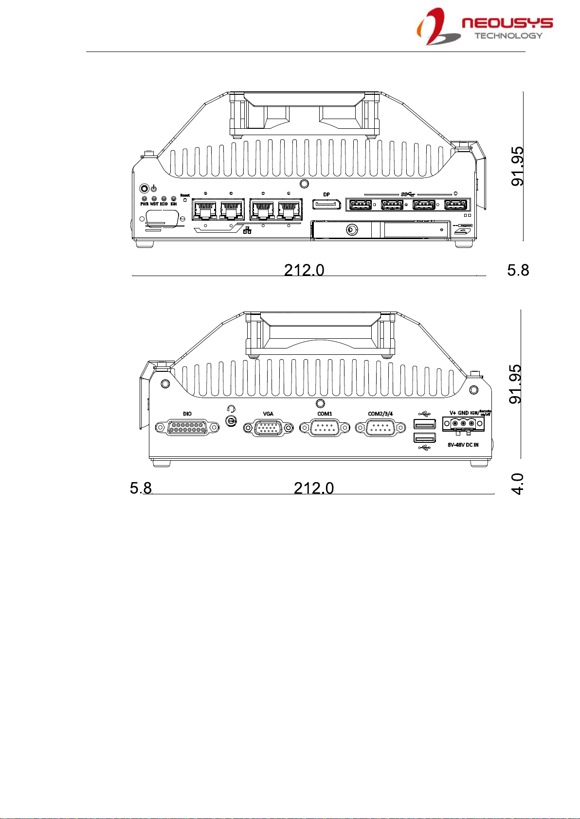
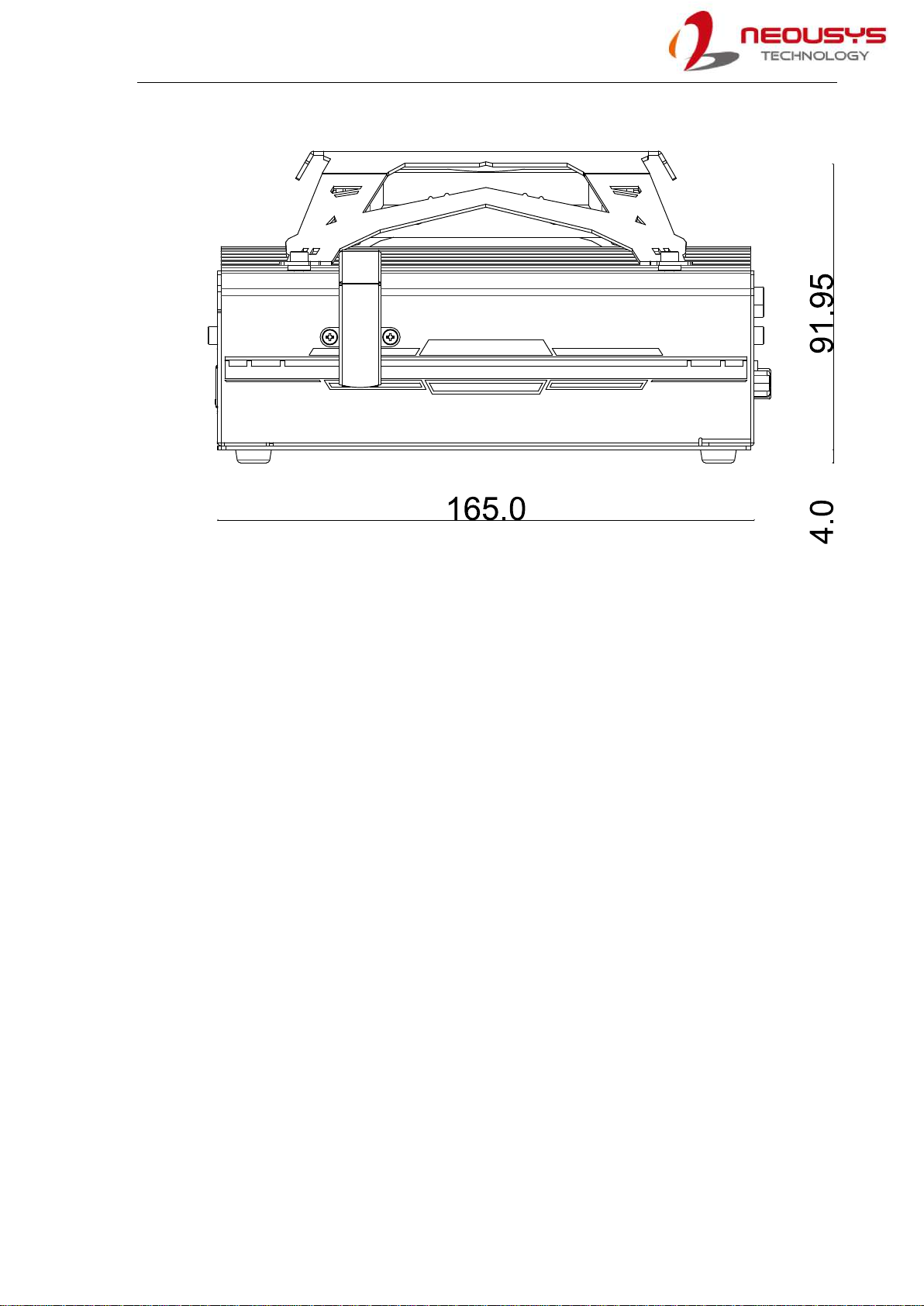
1.2 Dimension
NOTE
All measurements are in millimeters (mm).
1.2.1 Top View of Nuvo-9531 Series
1.2.2 Front View of Nuvo-9531 Series

Nuvo-9531 Series
15
1.2.3 Back View of Nuvo-9531 Series
1.2.4 Side View of Nuvo-9531 Series
1.3 Dimension with Fan Kit
The fan kit is available for users when a 65W CPU is installed in the system.
NOTE
All measurements are in millimeters (mm).

Nuvo-9531 Series
16
1.3.1 Top View with Fan Kit
Nuvo-9531 Series
17
1.3.2 Front View with Fan Kit
1.3.3 Back View with Fan Kit
Nuvo-9531 Series
18
1.3.4 Side View with Fan Kit

Nuvo-9531 Series
19
2 System Overview
Upon receiving and unpacking your Nuvo-9531, please check immediately if the package
contains all the items listed in the following table. If any item(s) are missing or damaged,
please contact your local dealer or Neousys Technology.
2.1 Nuvo-9531 Series Packing List
System
Pack Nuvo-9531 Qty
1 Nuvo-9531
(If you ordered CPU/ RAM/ HDD, please verify these items) 1
2
Accessory box, which contains
CPU bracket
mPCIe/ M.2 E key thermal pad
3-pin power terminal block
Screw pack
1
3
1
4

Nuvo-9531 Series
20
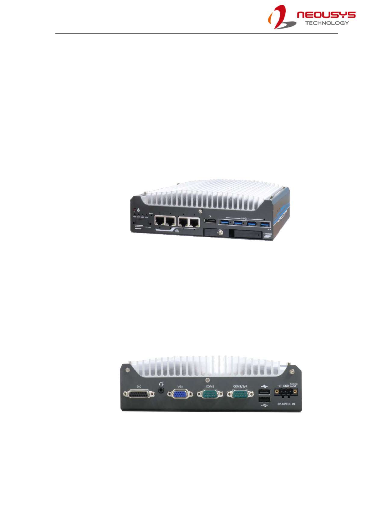
2.2 Front Panel I/O
The Nuvo-9531 I/O panel features four 2.5G Ethernet ports, four USB3.2 Gen1 ports, one
DisplayPort and a 2.5” hot-swappable tray.
No. Item Description
1 Power Button Use this button to turn on or shutdown the system.
2 System status
LEDs
Four system LEDs, power (PWR), watchdog timer (WDT),
hard disk drive (HDD) and ignition (IGN).
3 Reset button Use this button to manually reset the system.
4 2.5G Ethernet Port
(optional PoE+)
The 2.5G Ethernet ports support 10/ 100/ 1000/ 2500 Mbps
network connections with optional PoE+.
5 DisplayPort
Support display resolutions up to 4096 x 2304. Compatible
with HDMI/ DVI via respective adapter cable (resolution may
vary).
6 USB3.2 Gen1 Ports USB 3.2 Gen1 port supports up to 5 Gbit/s data transfer
bandwidth.
7 CMOS Reset
Button Use this button to manually reset the CMOS.
Area in red 2.5” HDD/ SSD hot swappable tray
Table of contents
Other Neousys Industrial PC manuals


Popular Industrial PC manuals by other brands

Allen-Bradley
Allen-Bradley 6155R-NSXP installation instructions

Hitachi
Hitachi HF-W7500 40 manual

CTC Parker Automation
CTC Parker Automation PC9 Hard Drive Installation

Siemens
Siemens Simatic IPC547G Product information

AXIOMTEK
AXIOMTEK eBOX627-312-FL-N3350-DC user manual

Siemens
Siemens SIMATIC IPC427E operating instructions

Hitachi
Hitachi CSNET MANAGER XT Installation and operation manual

IEI Technology
IEI Technology HTB-200-C236 user manual

Moxa Technologies
Moxa Technologies DA-681-I-SP-CE Quick installation guide

Siemens
Siemens SIMATIC IPC547J operating instructions

DFI
DFI EC700-BT Quick installation guide

Nodka
Nodka TPC6000-CXX3 Series user manual


