Neousys POC-500 Series User manual

Neousys Technology Inc.
POC-500 Series
User Manual
Revision 1.0

Table of Content
Table of Contents
Table of Contents...................................................................................................................2
Legal Information...................................................................................................................5
Contact Information...............................................................................................................6
Declaration of Conformity.....................................................................................................6
Copyright Notice....................................................................................................................7
Safety Precautions.................................................................................................................8
Service and Maintenance ......................................................................................................9
ESD Precautions....................................................................................................................9
About This Manual...............................................................................................................10
1Introduction
1.1 Specification of POC-515.........................................................................................12
1.2 Specification of POC-516.........................................................................................14
1.3 Specification of POC-545.........................................................................................16
1.4 Specification of POC-546.........................................................................................18
1.5 Dimension of POC-515/ POC-516............................................................................20
1.5.1 Front Panel View...............................................................................................20
1.5.2 DIO Panel View.................................................................................................21
1.5.3 COM and Audio Port Panel View......................................................................21
1.5.4 Bottom View......................................................................................................22
1.6 Dimension of POC-545/ POC-546............................................................................23
1.6.1 Front Panel View...............................................................................................23
1.6.2 DIO Panel View.................................................................................................24
1.6.3 COM and Audio Port Panel View ......................................................................24
1.6.4 Bottom View......................................................................................................25
2System Overview
2.1 Unpacking the System.............................................................................................26
2.2 POC-500 Series Front Panel....................................................................................27
2.2.1 3-pin Terminal Block for DC Input (Optional Ignition Input)...............................28
2.2.2 3-pin Remote On/ Off........................................................................................29
2.2.3 IEEE 802.3at Power over Ethernet Port............................................................30
2.2.4 USB 3.1 Gen1...................................................................................................31
2.2.5 System Status LED...........................................................................................31
2.2.6 DisplayPort........................................................................................................32
2.2.7 VGA Port...........................................................................................................33
2.3 COM Port Panel ........................................................................................................34
2.3.1 Power Button ....................................................................................................35
2.3.2 COM 1 Port.......................................................................................................36
2.3.3 COM Port (COM2/ COM3/ COM4)....................................................................37
2.3.4 4-Pole 3.5mm Microphone-in/ Speaker-out Jack..............................................38
2.3.5 SMAAntenna Opening......................................................................................39
2.4 Reserved Port Opening Panel.................................................................................40
2.5 Internal I/O.................................................................................................................41
2.5.1 Full-size mini-PCIe Slot and SIM Socket ..........................................................41
2.5.2 M.2 2280 (M Key) Slot for NVMe SSD..............................................................43
2.5.3 SO-DIMM Socket..............................................................................................45
2.6 MezIOTM Interface .....................................................................................................46
2.6.1 MezIOTM Interface Pin Definition.......................................................................47
2.6.2 MezIOTM Modules for POC-500 Series.............................................................48
3System Installation
3.1 Disassembling the System Enclosure....................................................................50
3.2 Installing Internal Components...............................................................................54
3.2.1 DDR4 SO-DIMM Installation.............................................................................54

Table of Content
3
3.2.2 mini-PCIe Module, SIM Card and Antenna Installation.....................................55
3.2.3 M.2 2880 M Key NVMe SSD Installation ..........................................................59
3.2.4 MezIOTM Module Installation.............................................................................61
3.3 Installing the System Enclosure .............................................................................63
3.4 DIN Rail Installation..................................................................................................66
3.5 Wall Mount Installation (Optional)...........................................................................69
3.5.1 Vertical Wall Mount Bracket (Optional)..............................................................70
3.6 Powering On the System .........................................................................................71
3.6.1 Powering On Using the Power Button...............................................................71
3.6.2 Powering On Using An External Non-Latched Switch.......................................72
3.6.3 Powering On Using Wake-on-LAN....................................................................73
4BIOS Settings
4.1 COM1/ 2 Port Configuration ....................................................................................77
4.2 COM 3/ 4 Port Configuration ...................................................................................78
4.3 COM Port High Speed Mode....................................................................................79
4.4 SATA Configuration for MezIOTM Module................................................................80
4.5 TPM Availability........................................................................................................81
4.6 System Power Configuration (POC-515/ 516)........................................................82
4.7 System Power Configuration (POC-545/ 546)........................................................83
4.8 Power over Ethernet (PoE) ......................................................................................84
4.9 Wake-on-LAN............................................................................................................85
4.10 Power On after Power Failure .................................................................................86
4.11 Boot Menu.................................................................................................................87
4.12 Boot Type (Legacy/ UEFI) ........................................................................................89
4.13 Position New Boot Device.......................................................................................90
4.14 Watchdog Timer .......................................................................................................91
5OS Support and Driver Installation
5.1 Operating System Compatibility.............................................................................92
5.2 Driver Installation.....................................................................................................93
5.2.1 Install Drivers Automatically..............................................................................93
5.2.2 Install Drivers Manually.....................................................................................94
5.3 Driver for Watchdog Timer and DIO........................................................................95
Appendix A Using WDT & DIO
WDT and DIO Library Installation.......................................................................................97
WDT Function Reference ....................................................................................................99
InitWDT..................................................................................................................................99
SetWDT .................................................................................................................................99
StartWDT.............................................................................................................................100
ResetWDT ...........................................................................................................................100
StopWDT .............................................................................................................................100
Using DIO Function (POC516/ POC-546 Only).................................................................101
Wiring for DIO ......................................................................................................................101
DIO Pin Definition.................................................................................................................102
DIO Function Reference ....................................................................................................103
InitDIO..................................................................................................................................103
DIReadLine..........................................................................................................................103
DIReadPort..........................................................................................................................103
DOWriteLine.........................................................................................................................104
DOWritePort.........................................................................................................................104
DOWriteLineChecked ..........................................................................................................105
DOWritePortChecked...........................................................................................................105
COS Function Reference...................................................................................................106
SetupDICOS ........................................................................................................................106
RegisterCallbackDICOS.......................................................................................................107
StartDICOS..........................................................................................................................107
StopDICOS ..........................................................................................................................107
DI COS Example..................................................................................................................108

Table of Content
4
Appendix B PoE On/ Off Control
PoE On/ Off Control Function Reference.........................................................................110
GetStatusPoEPort................................................................................................................110
EnablePoEPort..................................................................................................................... 111
DisablePoEPort....................................................................................................................112

Legal Information
Legal Information
All Neousys Technology Inc. products shall be subject to the latest Standard
Warranty Policy
Neousys Technology Inc. may modify, update or upgrade the software, firmware or
any accompanying user documentation without any prior notice. Neousys
Technology Inc. will provide access to these new software, firmware or
documentation releases from download sections of our website or through our
service partners.
Before installing any software, applications or components provided by a third party,
customer should ensure that they are compatible and interoperable with Neousys
Technology Inc. product by checking in advance with Neousys Technology Inc..
Customer is solely responsible for ensuring the compatibility and interoperability of
the third party’s products. Customer is further solely responsible for ensuring its
systems, software, and data are adequately backed up as a precaution against
possible failures, alternation, or loss.
For questions in regards to hardware/ software compatibility, customers should
contact Neousys Technology Inc. sales representative or technical support.
To the extent permitted by applicable laws, Neousys Technology Inc. shall NOT be
responsible for any interoperability or compatibility issues that may arise when (1)
products, software, or options not certified and supported; (2) configurations not
certified and supported are used; (3) parts intended for one system is installed in
another system of different make or model.

Contact Information/ Declaration of Conformity
Contact Information
Headquarters
(Taipei, Taiwan)
Neousys Technology Inc.
15F, No.868-3, Zhongzheng Rd., Zhonghe Dist., New Taipei City, 23586, Taiwan
Tel: +886-2-2223-6182 Fax: +886-2-2223-6183 Email, Website
Americas
(Illinois, USA)
Neousys Technology America Inc.
3384 CommercialAvenue, Northbrook, IL 60062, USA
Tel: +1-847-656-3298 Email, Website
China Neousys Technology China Co., Ltd.
Room 612, Building 32, Guiping Road 680, Shanghai
Tel: +86-2161155366 Email, Website
Declaration of Conformity
FCC This equipment has been tested and found to comply with the limits for a Class
A digital device, pursuant to part 15 of the FCC Rules. These limits are
designed to provide reasonable protection against harmful interference when
the equipment is operated in a commercial environment. This equipment
generates, uses, and can radiate radio frequency energy and, if not installed
and used in accordance with the instruction manual, may cause harmful
interference to radio communications. Operation of this equipment in a
residential area is likely to cause harmful interference in which case the user will
be required to correct the interference at own expense.
CE The product(s) described in this manual complies with all applicable European
Union (CE) directives if it has a CE marking. For computer systems to remain
CE compliant, only CE-
compliant parts may be used. Maintaining CE
compliance also requires proper cable and cabling techniques.

Copyright Notice
Copyright Notice
All rights reserved. This publication may not be reproduced, transmitted,
transcribed, stored in a retrieval system, or translated into any language or
computer language, in any form or by any means, electronic, mechanical,
magnetic, optical, chemical, manual or otherwise, without the prior written
consent of Neousys Technology, Inc.
Disclaimer This manual is intended to be used as an informative guide only and is subject
to change without prior notice. It does not represent commitment from Neousys
Technology Inc. Neousys Technology Inc. shall not be liable for any direct,
indirect, special, incidental, or consequential damages arising from the use of
the product or documentation, nor for any infringement on third party rights.
Patents and
Trademarks
Neousys, the Neousys logo, Expansion Cassette, MezIOTM are registered
patents and trademarks of Neousys Technology, Inc.
Windows is a registered trademark of Microsoft Corporation.
AMD, Ryzen™ are registered trademarks of Advanced Micro Devices, Inc
All other names, brands, products or services are trademarks or registered
trademarks of their respective owners.

Safety Precautions
Safety Precautions
Read these instructions carefully before you install, operate, or transport the
system.
Install the system or DIN rail associated with, at a sturdy location
Install the power socket outlet near the system where it is easily accessible
Secure each system module(s) using its retaining screws
Place power cords and other connection cables away from foot traffic. Do not
place items over power cords and make sure they do not rest against data
cables
Shutdown, disconnect all cables from the system and ground yourself before
touching internal modules
Ensure that the correct power range is being used before powering the device
Should a module fail, arrange for a replacement as soon as possible to minimize
down-time
If the system is not going to be used for a long time, disconnect it from mains
(power socket) to avoid transient over-voltage

Service and Maintenance/ ESD Precautions
Service and Maintenance
ONLY qualified personnel should service the system
Shutdown the system, disconnect the power cord and all other connections
before servicing the system
When replacing/ installing additional components (expansion card, memory
module, etc.), insert them as gently as possible while assuring proper
connector engagement
ESD Precautions
Handle add-on module, motherboard by their retention screws or the module’s
frame/ heat sink. Avoid touching the PCB circuit board or add-on module
connector pins
Use a grounded wrist strap and an anti-static work pad to discharge static
electricity when installing or maintaining the system
Avoid dust, debris, carpets, plastic, vinyl and styrofoam in your work area.
Do not remove any module or component from its anti-static bag before
installation

About This Manual
10
About This Manual
This manual introduces and demonstrates installation procedures of Neousys
POC-500 series systems featuring AMD Ryzen™ Embedded V1000 4-core/ 8-thread
processor. The manual also demonstrates the system’s general installation
procedures.
Revision History
Version Date Description
1.0 Oct. 2019 Initial release
POC-500 Series
11
1 Introduction
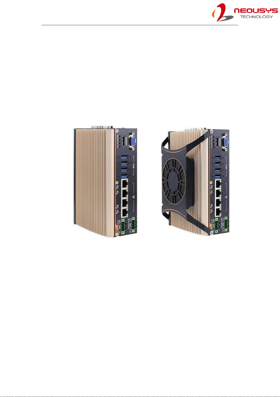
POC-500 series is an ultra-compact embedded controller offering performances
never-seen-before in this form factor. Featuring AMD Ryzen™ Embedded V1000
4-core/ 8-thread processor, it delivers up to 3x times the CPU performance over
previous POC series. GPU performance wise, it delivers an unheard of 3.6 TFLOPS
in FP16 for an ultra-compact form factor embedded controller. Another amazing feat
is that it manages to incorporate an M.2 2280 NVMe SSD to support 2x times the
disk read/ write speed over typical 2.5" SATA SSDs.
POC-515/ 516 POC-545/ 546
POC-500 series continues the POC series ingenious mechanical design that can be
DIN-rail mounted and offers plenty of front-accessible I/Os. Measuring just 64.36 x
175.8 x 115.5 mm (2.5” x 6.9” x 4.6”), it has 4x PoE+ ports, 4x USB 3.1 Gen1 ports
and 4x COM ports. And best of all, all data ports come with screw-lock mechanisms
so you can be rest assured that cables are always secured. POC-500 series is
available in two CPU variants, the V1807B (45W) variant is for high computing power
demand and the V1605B (15W) variant is designed for rugged fanless operation.
POC-500 Series
12
1.1 Specification of POC-515
System Core
Processor AMD RyzenTM V1605B CPU ( 4C/ 8T, 2M Cache, 2.0/ 3.6 GHz)
Graphics Vega GPU with 8 compute units
Memory Up to 16 GB DDR4-2400 SDRAM (one SODIMM socket)
Panel I/O Interface
PoE+ 4x IEEE 802.3at Gigabit PoE+ ports by Intel® I350-AM4 with
screw-lock
USB 4x USB 3.1 Gen1 ports with screw-lock
Video port 1x VGA connector, supporting 1920 x 1200 resolution
1x DisplayPort connector, supporting 4096 x 2160 resolution
Serial port 1x software-programmable RS-232/ 422/ 485 port (COM1)
3x 3-wire RS-232 ports (COM2/ 3/ 4) or 1x RS-422/ 485 port (COM2)
Audio 1x 3.5mm jack for mic-in and speaker-out
Internal I/O Interface
Mini PCI-E 1x full-size mini PCI Express socket with internal SIM socket
Expandable
I/O 1x MezIOTM expansion interface for Neousys MezIOTM modules
Storage Interface
M.2 NVMe 1x M.2 2280 M key NVMe socket (PCIe Gen3 x2) for NVMe SSD
installation
Power Supply
DC input 1x 3-pin pluggable terminal block for 8~35VDC DC input
Remote
Ctrl.& LED
output
1x3-pin pluggable terminal block for remote control and PWR LED
output
Mechanical
Dimension 64.4 mm (W) x 115.5 mm (D) x 175.8 mm (H)
Weight 1.2kg
Mounting DIN-rail mount (standard) or wall-mount (optional)
Environmental
Operating
temperature -25°C ~ 70°C *
Storage
temperature -40°C ~85°C
Humidity 10%~90% , non-condensing

POC-500 Series
13
Vibration Operating, MIL-STD-810G, Method 514.6, Category 4
Shock Operating, MIL-STD-810G, Method 516.6, Procedure I, Table 516.6-II)
EMC CE/ FCC Class A, according to EN 55032 & EN 55024
* For sub-zero and over 60°C operating temperature, a wide temperature HDD or
Solid State Disk (SSD) is required.

POC-500 Series
14
1.2 Specification of POC-516
System Core
Processor AMD RyzenTM V1605B CPU ( 4C/ 8T, 2M Cache, 2.0/ 3.6 GHz)
Graphics Vega GPU with 8 compute units
Memory Up to 16 GB DDR4-2400 SDRAM (one SODIMM socket)
Panel I/O Interface
Isolated
digital output 4-CH isolated digital output
Isolated
digital input 4-CH isolated digital input
Ethernet 4x IEEE 802.3at Gigabit PoE+ ports by Intel® I350-AM4 with
screw-lock
USB 4x USB 3.1 Gen1 ports with screw-lock
Video port 1x VGA connector, supporting 1920 x 1200 resolution
1x DisplayPort connector, supporting 4096 x 2160 resolution
Serial port 1x software-programmable RS-232/ 422/ 485 port (COM1)
3x 3-wire RS-232 ports (COM2/ 3/ 4) or 1x RS-422/ 485 port (COM2)
Audio 1x 3.5mm jack for mic-in and speaker-out
Internal I/O Interface
Mini PCI-E 1x full-size mini PCI Express socket with internal SIM socket
Storage Interface
M.2 NVMe 1x M.2 2280 M key NVMe socket (PCIe Gen3 x2)
SATA 1x SATA interface for 2.5” SSD/ HDD
Power Supply
DC input 1x 3-pin pluggable terminal block for 8~35VDC DC input
Remote
Ctrl.& LED
output
1x3-pin pluggable terminal block for remote control and PWR LED
output
Mechanical
Dimension 64.4 mm (W) x 115.5 mm (D) x 175.8 mm (H)
Weight 1.2kg
Mounting DIN-rail mount (standard) or wall-mount (optional)
Environmental
Operating
temperature -25°C ~ 70°C *

POC-500 Series
15
Storage
temperature -40°C ~85°C
Humidity 10%~90% , non-condensing
Vibration Operating, MIL-STD-810G, Method 514.6, Category 4
Shock Operating, MIL-STD-810G, Method 516.6, Procedure I, Table 516.6-II)
EMC CE/ FCC Class A, according to EN 55032 & EN 55024
* For sub-zero and over 60°C operating temperature, a wide temperature HDD or
Solid State Disk (SSD) is required.

POC-500 Series
16
1.3 Specification of POC-545
System Core
Processor AMD RyzenTM V1807B CPU ( 4C/ 8T, 2M Cache, 3.35/ 3.8 GHz)
Graphics Vega GPU with 11 compute units
Memory Up to 16 GB DDR4-3200 SDRAM (one SODIMM socket)
Panel I/O Interface
Ethernet 4x IEEE 802.3at Gigabit PoE+ ports by Intel® I350-AM4 with
screw-lock
USB 4x USB 3.1 Gen1 ports with screw-lock
Video port 1x VGA connector, supporting 1920 x 1200 resolution
1x DisplayPort connector, supporting 4096 x 2160 resolution
Serial port 1x software-programmable RS-232/ 422/ 485 port (COM1)
3x 3-wire RS-232 ports (COM2/ 3/ 4) or 1x RS-422/ 485 port (COM2)
Audio 1x 3.5mm jack for mic-in and speaker-out
Internal I/O Interface
Mini PCI-E 1x full-size mini PCI Express socket with internal SIM socket
Expandable
I/O 1x MezIOTM expansion interface for Neousys MezIOTM modules
Storage Interface
M.2 NVMe 1x M.2 2280 M key NVMe socket (PCIe Gen3 x2)
Power Supply
DC input 1x 3-pin pluggable terminal block for 8~35VDC DC input
Remote
Ctrl.& LED
output
1x3-pin pluggable terminal block for remote control and PWR LED
output
Mechanical
Dimension 82.2 mm (W) x 117.9 mm (D) x 175.8 mm (H)
Weight 1.4kg
Mounting DIN-rail mount (standard) or wall-mount (optional)
Fan External-accessible 80mm x 80mm fan for system heat dissipation
Environmental
Operating
temperature -25°C ~ 70°C */**
Storage
temperature -40°C ~85°C

POC-500 Series
17
Humidity 10%~90% , non-condensing
Vibration Operating, MIL-STD-810G, Method 514.6, Category 4
Shock Operating, MIL-STD-810G, Method 516.6, Procedure I, Table 516.6-II)
EMC CE/ FCC Class A, according to EN 55032 & EN 55024
* For sub-zero and over 60°C operating temperature, a wide temperature HDD or
Solid State Disk (SSD) is required.
** Operating temperature is up to 70°C only if the external-accessible fan is installed.

POC-500 Series
18
1.4 Specification of POC-546
System Core
Processor AMD RyzenTM V1807B CPU ( 4C/ 8T, 2M Cache, 3.35/ 3.8 GHz)
Graphics Vega GPU with 11 compute units
Memory Up to 16 GB DDR4-3200 SDRAM (one SODIMM socket)
Panel I/O Interface
Isolated
digital output 4-CH isolated digital output
Isolated
digital input 4-CH isolated digital input
Ethernet 4x IEEE 802.3at Gigabit PoE+ ports by Intel® I350-AM4 with
screw-lock
Video port 1x VGA connector, supporting 1920 x 1200 resolution
1x DisplayPort connector, supporting 4096 x 2160 resolution
Serial port 1x software-programmable RS-232/ 422/ 485 port (COM1)
3x 3-wire RS-232 ports (COM2/ 3/ 4) or 1x RS-422/ 485 port (COM2)
USB 4x USB 3.1 Gen1 ports with screw-lock
Audio 1x 3.5mm jack for mic-in and speaker-out
Internal I/O Interface
Mini PCI-E 1x full-size mini PCI Express socket with internal SIM socket
Storage Interface
M.2 NVMe 1x M.2 2280 M key NVMe socket (PCIe Gen3 x2)
SATA 1x SATA interface for 2.5” SSD/ HDD
Power Supply
DC input 1x 3-pin pluggable terminal block for 8~35VDC DC input
Remote
Ctrl.& LED
output
1x3-pin pluggable terminal block for remote control and PWR LED
output
Mechanical
Dimension 82.2 mm (W) x 117.9 mm (D) x 175.8 mm (H)
Weight 1.4kg
Mounting DIN-rail mount (standard) or wall-mount (optional)
Fan External-accessible 80mm x 80mm fan for system heat dissipation
Environmental
Operating
temperature -25°C ~ 70°C */**

POC-500 Series
19
Storage
temperature -40°C ~85°C
Humidity 10%~90% , non-condensing
Vibration Operating, MIL-STD-810G, Method 514.6, Category 4
Shock Operating, MIL-STD-810G, Method 516.6, Procedure I, Table 516.6-II)
EMC CE/ FCC Class A, according to EN 55032 & EN 55024
* For sub-zero and over 60°C operating temperature, a wide temperature HDD or
Solid State Disk (SSD) is required.
** Operating temperature is up to 70°C only if the external-accessible fan is installed.

POC-500 Series
20
1.5 Dimension of POC-515/ POC-516
NOTE
All measurements are in millimeters (mm).
The POC-515 and POC-516 systems share the same dimensions.
1.5.1 Front Panel View
This manual suits for next models
4
Table of contents
Other Neousys Industrial PC manuals


