Neousys SEMIL-1700 Series User manual

Neousys Technology Inc.
SEMIL-1700 Series
User Manual
Rev. 1.3

Table of Contents
Table of Contents
Table of Contents...................................................................................................................2
Legal Information...................................................................................................................5
Contact Information...............................................................................................................6
Declaration of Conformity.....................................................................................................6
Copyright Notice....................................................................................................................7
Safety Precautions.................................................................................................................8
Battery Warning......................................................................................................................8
Service and Maintenance ......................................................................................................9
ESD Precautions....................................................................................................................9
Restricted Access Location ..................................................................................................9
About This Manual...............................................................................................................10
1Introduction
1.1 SEMIL-1700 Series Overview...................................................................................12
1.2 SEMIL-1704 Specifications......................................................................................13
1.3 SEMIL-1708 Specifications......................................................................................15
1.4 SEMIL-1714J Specifications....................................................................................17
1.5 SEMIL-1718J Specifications....................................................................................19
1.6 Dimension.................................................................................................................21
1.6.1 Superior View....................................................................................................21
1.6.2 Front Panel View...............................................................................................22
1.6.3 Side View..........................................................................................................22
1.6.4 Bottom View......................................................................................................23
1.7 Dimensions with Wall Mount Bracket.....................................................................24
1.7.1 Front View.........................................................................................................24
1.7.2 Bottom View......................................................................................................24
2System Overview
2.1 SEMIL-1700 Packing List .........................................................................................25
2.2 SEMIL-1700 Front Panel...........................................................................................26
2.2.1 DC-IN Connector ..............................................................................................27
2.2.2 PoE+ Gigabit Ethernet Port...............................................................................28
2.2.3 USB Port...........................................................................................................30
2.2.4 VGA Port...........................................................................................................31
2.2.5 Audio Port (SEMIL-17x8 Models Only).............................................................33
2.2.6 COM1/ COM2 Port............................................................................................34
2.2.7 Power Button ....................................................................................................35
2.2.8 Optional 10Gb Ethernet....................................................................................36
2.3 Internal I/Os...............................................................................................................37
2.3.1 mini-PCIe Expansion Slot (mux with mSATA)...................................................37
2.3.2 mini-PCIe Expansion Slot (SEMIL-17x8 Models Only) .....................................39
2.3.3 Ignition Control Rotary Switch...........................................................................41
3Installation
3.1 mini-PCIe Module Installation .................................................................................42
3.2 Hard Drive Installation .............................................................................................48
3.3 Wall-mount Bracket Installation..............................................................................53
3.4 Rack-mount Bracket Installation (Optional Accessory)........................................54
4Ignition Power Control
4.1 Principles of Ignition Power Control.......................................................................55
4.2 Additional Features of Ignition Power Control ......................................................56
4.3 Wiring Ignition Signal...............................................................................................57

Table of Contents
3
4.4 Configure your Windows system............................................................................58
4.5 Accessing the Rotary Switch ..................................................................................59
4.6 Operation Modes of Ignition Power Control ..........................................................60
4.7 Reinstalling the Backplate.......................................................................................62
4.8 Ignition Control Setup..............................................................................................63
5System Configuration
5.1 BIOS Settings ...........................................................................................................66
5.1.1 COM Port Configuration....................................................................................67
5.1.2 COM Port High Speed Mode ............................................................................68
5.1.3 Delay for PEG Initialization ...............................................................................69
5.1.4 SATA Configuration...........................................................................................70
5.1.5 TPM Availability.................................................................................................72
5.1.6 Auto Wake on S5..............................................................................................73
5.1.7 Power On After Power Failure Option...............................................................74
5.1.8 Power & Performance (CPU SKU Power Configuration)..................................75
5.1.9 Wake on LAN Option ........................................................................................76
5.1.10 Boot Menu ........................................................................................................77
5.1.11 Boot Type (Legacy/ UEFI).................................................................................79
5.1.12 Boot Option for Newly Added Device................................................................80
5.1.13 Watchdog Timer for Booting..............................................................................81
5.1.14 Selecting Legacy/ UEFI Boot Device................................................................82
5.2 AMT Configuration...................................................................................................83
5.3 RAID Volume Configuration.....................................................................................84
5.3.1 Legacy Mode RAID Configuration.....................................................................84
5.3.2 UEFI Mode RAID Configuration........................................................................90
6OS Support and Driver Installation
6.1 Operating System Compatibility...........................................................................100
6.2 Install Drivers Automatically .................................................................................101
6.2.1 Install Drivers Automatically............................................................................101
6.3 Install Drivers Manually .........................................................................................102
6.3.1 For Windows 10 (x64).....................................................................................102
6.4 Driver Installation for Watchdog Timer Control...................................................103
6.5 Intel®OptaneTM Memory BIOS Setup and Driver Installation..............................104
7CAP Energy Management Technology ~ Power Backup Parameter
Configurer
7.1 CAP Energy Management Technology.................................................................113
7.2 Power Backup Parameter Configurer...................................................................114
7.2.1 Executing PB2500J Parameter Configurer..................................................... 114
7.2.2 PB-2500J Parameter Configurer.....................................................................115
7.2.3 Auto-start ........................................................................................................116
7.2.4 Behavior for DC Loss (<9V)............................................................................117
7.2.5 Shutdown at Low Voltage ...............................................................................118
7.2.6 Shutdown at High Voltage...............................................................................119
7.2.7 SuperCAP Lifetime Extension.........................................................................120
7.2.8 Update Parameters.........................................................................................121
7.2.9 Get Parameters...............................................................................................122
7.2.10 Load Default....................................................................................................123
7.2.11 Re-train...........................................................................................................124
7.2.12 Reset ..............................................................................................................125
Appendix A: Using WDT & DIO
WDT and DIO Library Installation.....................................................................................127
WDT Function Reference ..................................................................................................129
InitWDT................................................................................................................................129

Table of Contents
4
SetWDT ...............................................................................................................................129
StartWDT.............................................................................................................................130
ResetWDT ...........................................................................................................................130
StopWDT .............................................................................................................................130
Appendix B: PoE On/ Off Control
GetStatusPoEPort................................................................................................................131
EnablePoEPort.....................................................................................................................132
DisablePoEPort....................................................................................................................133

Legal Information
Legal Information
All Neousys Technology Inc. products shall be subject to the latest Standard
Warranty Policy
Neousys Technology Inc. may modify, update or upgrade the software, firmware or
any accompanying user documentation without any prior notice. Neousys
Technology Inc. will provide access to these new software, firmware or
documentation releases from download sections of our website or through our
service partners.
Before installing any software, applications or components provided by a third party,
customer should ensure that they are compatible and interoperable with Neousys
Technology Inc. product by checking in advance with Neousys Technology Inc..
Customer is solely responsible for ensuring the compatibility and interoperability of
the third party’s products. Customer is further solely responsible for ensuring its
systems, software, and data are adequately backed up as a precaution against
possible failures, alternation, or loss.
For questions in regards to hardware/ software compatibility, customers should
contact Neousys Technology Inc. sales representative or technical support.
To the extent permitted by applicable laws, Neousys Technology Inc. shall NOT be
responsible for any interoperability or compatibility issues that may arise when (1)
products, software, or options not certified and supported; (2) configurations not
certified and supported are used; (3) parts intended for one system is installed in
another system of different make or model.

Contact Information / Declaration of Conformity
Contact Information
Headquarters
(Taipei, Taiwan)
Neousys Technology Inc.
15F, No.868-3, Zhongzheng Rd., Zhonghe Dist., New Taipei City, 23586, Taiwan
Tel: +886-2-2223-6182 Fax: +886-2-2223-6183 Email, Website
Americas
(Illinois, USA)
Neousys Technology America Inc.
3384 Commercial Avenue, Northbrook, IL 60062, USA
Tel: +1-847-656-3298 Email, Website
China
Neousys Technology (China) Ltd.
Room 612, Building 32, Guiping Road 680, Shanghai
Tel: +86-2161155366 Email, Website
Declaration of Conformity
FCC
This equipment has been tested and found to comply with the limits for a Class
A digital device, pursuant to part 15 of the FCC Rules. These limits are
designed to provide reasonable protection against harmful interference when
the equipment is operated in a commercial environment. This equipment
generates, uses, and can radiate radio frequency energy and, if not installed
and used in accordance with the instruction manual, may cause harmful
interference to radio communications. Operation of this equipment in a
residential area is likely to cause harmful interference in which case the user will
be required to correct the interference at own expense.
CE
The product(s) described in this manual complies with all applicable European
Union (CE) directives if it has a CE marking. For computer systems to remain
CE compliant, only CE-compliant parts may be used. Maintaining CE
compliance also requires proper cable and cabling techniques.

Copyright Notice
Copyright Notice
All rights reserved. This publication may not be reproduced, transmitted,
transcribed, stored in a retrieval system, or translated into any language or
computer language, in any form or by any means, electronic, mechanical,
magnetic, optical, chemical, manual or otherwise, without the prior written
consent of Neousys Technology, Inc.
Disclaimer
This manual is intended to be used as an informative guide only and is subject
to change without prior notice. It does not represent commitment from Neousys
Technology Inc. Neousys Technology Inc. shall not be liable for any direct,
indirect, special, incidental, or consequential damages arising from the use of
the product or documentation, nor for any infringement on third party rights.
Patents and
Trademarks
Neousys, the Neousys logo, Expansion Cassette, MezIOTM are registered
patents and trademarks of Neousys Technology, Inc.
Windows is a registered trademark of Microsoft Corporation.
Intel®, Core™is a registered trademark of Intel Corporation
NVIDIA®, GeForce®is a registered trademark of NVIDIA Corporation
Texas Instruments (TI) and Sitara are registered trademarks of Texas
Instruments Incorporated.
All other names, brands, products or services are trademarks or registered
trademarks of their respective owners.

Safety Precautions
Safety Precautions
⚫Read these instructions carefully before you install, operate, or transport the
system.
⚫Install the system or DIN rail associated with, at a sturdy location
⚫Install the power socket outlet near the system where it is easily accessible
⚫Secure each system module(s) using its retaining screws
⚫Place power cords and other connection cables away from foot traffic. Do not
place items over power cords and make sure they do not rest against data
cables
⚫Shutdown, disconnect all cables from the system and ground yourself before
touching internal modules
⚫Ensure that the correct power range is being used before powering the device
⚫Should a module fail, arrange for a replacement as soon as possible to
minimize down-time
⚫If the system is not going to be used for a long time, disconnect it from mains
(power socket) to avoid transient over-voltage
Battery Warning
⚫Batteries are at risk of exploding if incorrectly installed
⚫Do not attempt to recharge, force open, or heat the
battery
⚫Replace the battery only with the same or equivalent type
recommended by the manufacturer

Service and Maintenance/ ESD Precautions
Service and Maintenance
⚫ONLY qualified personnel should service the system
⚫Shutdown the system, disconnect the power cord and all other connections
before servicing the system
⚫When replacing/ installing additional components (expansion card, memory
module, etc.), insert them as gently as possible while assuring connectors are
properly engaged
ESD Precautions
⚫Handle add-on module, motherboard by their retention screws or the module’s
frame/ heat sink. Avoid touching the PCB circuit board or add-on module
connector pins
⚫Use a grounded wrist strap and an anti-static work pad to discharge static
electricity when installing or maintaining the system
⚫Avoid dust, debris, carpets, plastic, vinyl and 9tyrofoam in your work area.
⚫Do not remove any module or component from its anti-static bag before
installation
Restricted Access Location
The controller is intended for installation only in the certain environment where both
these condition apply:
⚫Access can only be gained by SERVICE PERSONS or by USERS who have
been instructed about the reasons for the restrictions applied to the location
and about any precautions that shall be taken
⚫Access is through the use of a TOOL or lock and key, or other means of
security, and is controlled by the authority responsible for the location
About This Manual
About This Manual
This manual introduces Neousys Technology SEMIL-1700 series, a 2U half-rack
IP67 waterproof extreme-rugged fanless computer. It features workstation-grade
Intel® chipset and offers excellent passive thermal performance with M12
connectors for robust and cost-effectiveness.
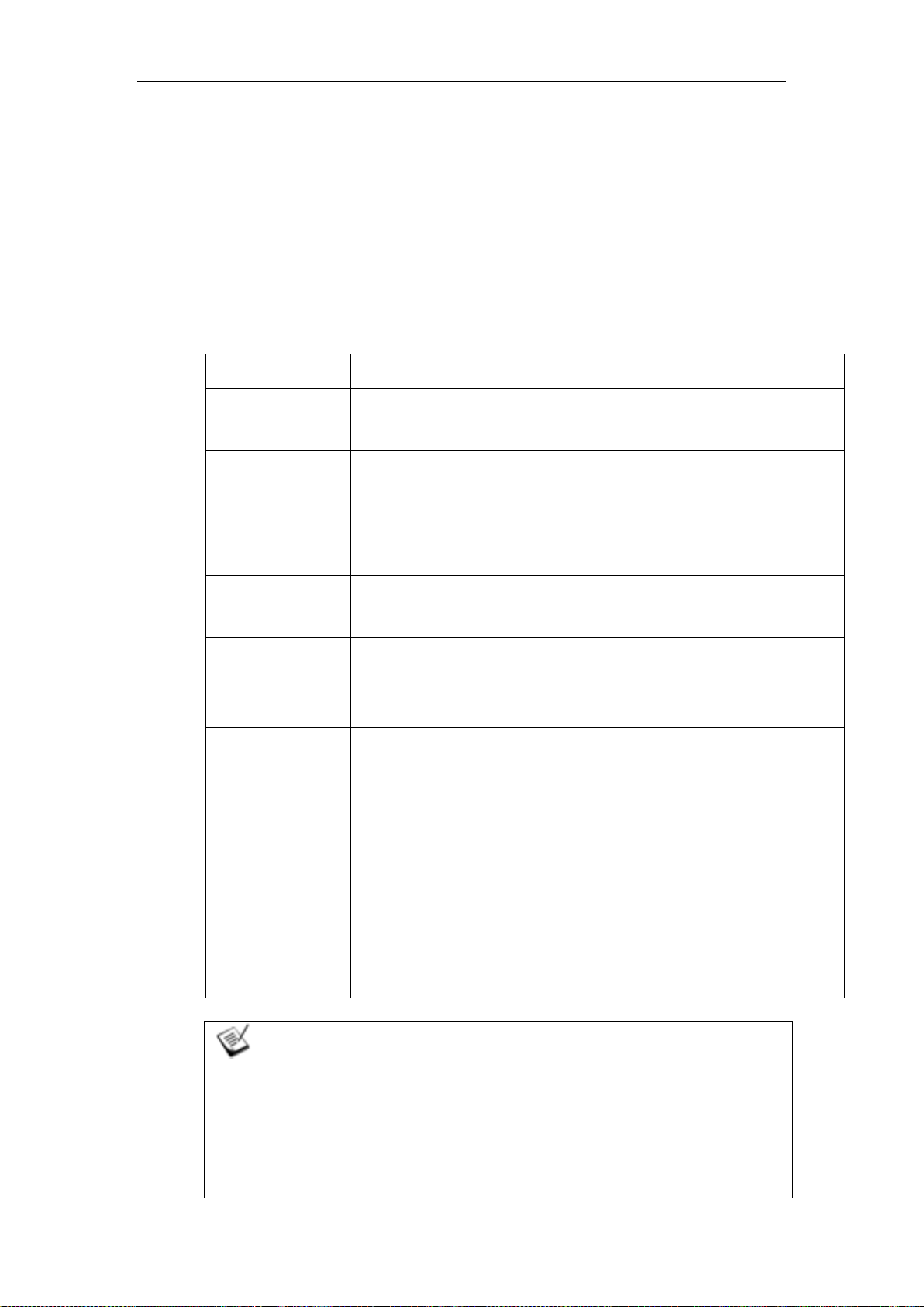
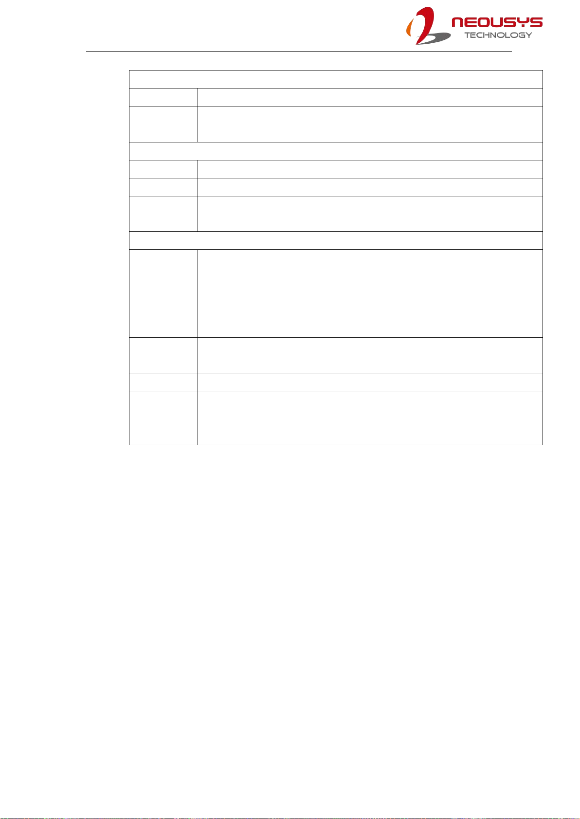
Applicable systems
Model No.
Description
SEMIL-1704
Half-rack IP67 waterproof computer including Intel® Xeon® E or 9th /
8th-Gen Core™processor with 4x M12 PoE+ ports
SEMIL-1704-10G
Half-rack IP67 waterproof computer including Intel® Xeon® E or 9th /
8th-Gen Core™processor with 4x M12 PoE+ ports and 10GbE port
SEMIL-1708
Half-rack IP67 waterproof computer including Intel® Xeon® E or 9th /
8th-Gen Core™processor with 8x M12 PoE+ ports
SEMIL-1708-10G
Half-rack IP67 waterproof computer including Intel® Xeon® E or 9th /
8th-Gen Core™processor with 8x M12 PoE+ ports and 10GbE port
SEMIL-1714J
Half-rack IP67 waterproof computer including Intel® Xeon® E or 9th /
8th-Gen Core™processor with 4x M12 PoE+ ports and 2500
watt-second SuperCAP UPS
SEMIL-1714J-10G
Half-rack IP67 waterproof computer including Intel® Xeon® E or 9th /
8th-Gen Core™processor with 4x M12 PoE+ ports, 2500
watt-second SuperCAP UPS and 10GbE port
SEMIL-1718J
Half-rack IP67 waterproof computer including Intel® Xeon® E or 9th /
8th-Gen Core™processor with 8x M12 PoE+ ports and 2500
watt-second SuperCAP UPS
SEMIL-1718J-10G
Half-rack IP67 waterproof computer including Intel® Xeon® E or 9th /
8th-Gen Core™processor with 8x M12 PoE+ ports and 2500
watt-second SuperCAP UPS and 10GbE port
NOTE
Installing after-sales internal modules on your own may affect its waterproof capabilities and
is not recommended. If you must install internal modules after purchase, please consult your
sales representative as you may need to return the system to Neousys Technology or an
authorized SEMIL distributor for processing.

11
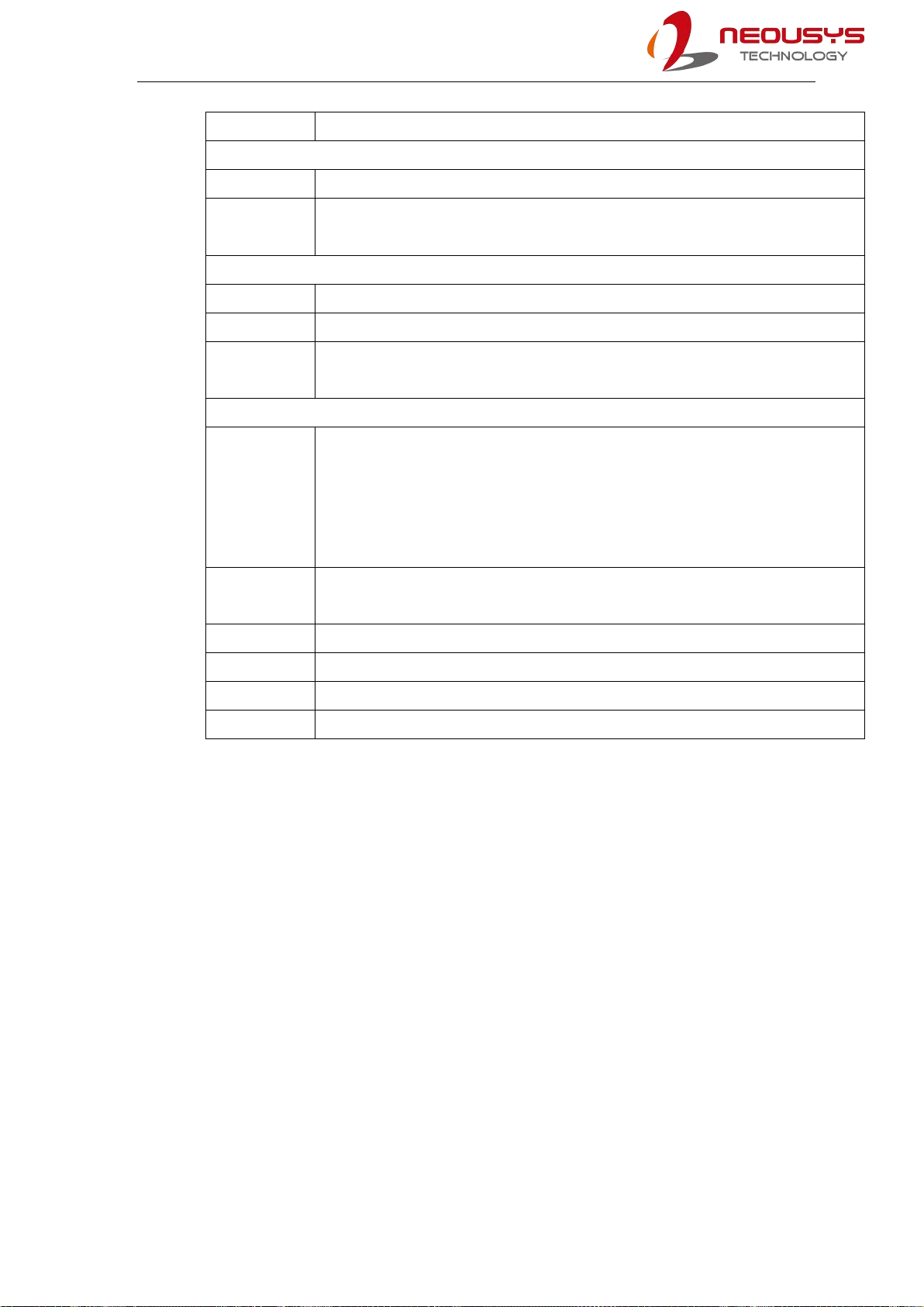
Revision History
Version
Date
Description
1.0
May. 2023
Initial release
1.1
May. 2023
Updated mini-PCIe specifications
1.2
Jun. 2023
Updated the unit for screw torque range, for securing the
enclosure panel
1.3
Nov. 2023
Updated ignition power control, supercapacitor
configuration, and optional 10G Ethernet descriptions

SEMIL-1700 Series
12
1 Introduction
SEMIL-1700 series is a 2U half-rack extreme-rugged IP67 waterproof capable computer that
features an Intel® work-station grade chipset to power a Xeon or 9th/ 8th-Gen Core™
processor. Coupled with M12 connectors, the system is design to meet the ever changing
harsh environmental conditions that can no longer be met by traditional industrial computers.
1.1 SEMIL-1700 Series Overview
SEMIL-1700 series is one of the world’s first IP67-rated, waterproof and dustproof
inference server. It takes industrial computing to a new level of robustness for rugged
edge AI solutions. Coupled with Intel® Xeon® E or 9th/ 8th-Gen Core™CPU, the system
is capable of delivering excellent CPU performances for advanced edge AI applications
in extreme environmental settings. With Neousys patented architecture, it guarantees -40
°C to 70°C fanless operation in a rack or wall-mountable 2U half-rack 19”enclosure.
Featuring a sophisticated thermal design, it effectively dissipates the heat in
high-temperature environments. Its enclosure is a corrosion-proof, stainless steel/
aluminum chassis with molded o-rings plus patented fusion mechanism design to offer
extraordinary durability and watertight construction. SEMIL-1700 series offers a variety of
I/O connectivity, including 802.3at Gigabit PoE+, VGA, USB, COM ports and optional
10G Ethernet, all using M12 connectors for water-proof and extreme-rugged connectivity.
Additionally, it features M.2 for NVMe SSD, 2.5”SATA storage accommodation, 8-48V
wide-range DC input with ignition power control and is in compliance with MIL-STD-810G
and EN 50155.
SEMIL-1700 Series
13
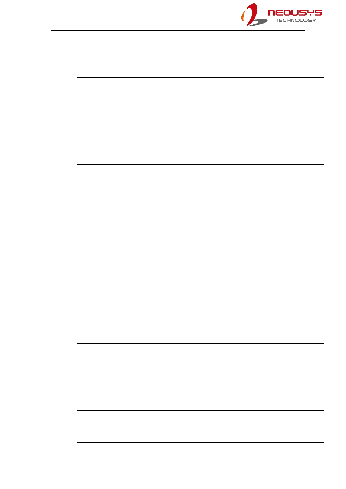
1.2 SEMIL-1704 Specifications
System Platform
Processor
Supporting Intel® Xeon® E and 9th/ 8th-Gen CPU (LGA1151 socket)
- Xeon E 2176G (6C/12T) / 2278GE (8C/16T) / 2278GEL (8C/16T)
- Intel® Core™i7-9700TE/ i7-9700E/ i7-8700T/ i7-8700
- Intel® Core™i5-9500TE/ i5-9500E/ i5-8500T/ i5-8500
- Intel® Core™i3-9100TE/ i3-9100E/ i3-8100T/ i3-8100
Chipset
Intel® C246 platform
Graphics
Integrated Intel® HD Graphics 630
Memory
2x 260-pin SO-DIMM sockets, up to 64GB DDR4 2666/ 2400MHz SDRAM
AMT
Supports AMT 12.0
TPM
Supports TPM 2.0
I/O Interface
PoE+
1x IEEE 802.3at (25.5W) Gigabit PoE+ ports by Intel® I219 (M12 X-coded)
3x IEEE 802.3at (25.5W) Gigabit PoE+ ports by Intel® I210 (M12 X-coded)
10 GbE Port
(Build
Option)
Optional: 1x 10 GbE port by Intel® X550AT controller (M12 X-coded)**
Native Video
Port
1x VGA (M12 A-coded), supporting 1920 x 1200 resolution
Serial Port
2x 3-wire RS-232 ports COM1 & COM2 (M12 A-coded)
USB
2x USB 2.0 (M12 A-coded)
1x USB 2.0 (internal)
Audio
NA
Storage Interface
SATA HDD
2x internal SATA ports for 2.5” HDD/ SSD installation, supporting RAID 0/ 1
mSATA
2x full-size mSATA ports (mux with mini-PCIe)
M.2
1x M.2 2280 M key socket (PCIe Gen3 x4) for NVMe SSD
or Intel® Optane™memory installation
Expansion Bus
Mini PCI-E
2x full-size mini PCI Express sockets (mux with mSATA)
Power Supply
DC Input
8 to 48V DC input (M12 S-coded)
Ignition
Control
Built-in ignition power control
(IGN/ GND signal via M12 serial port connector)
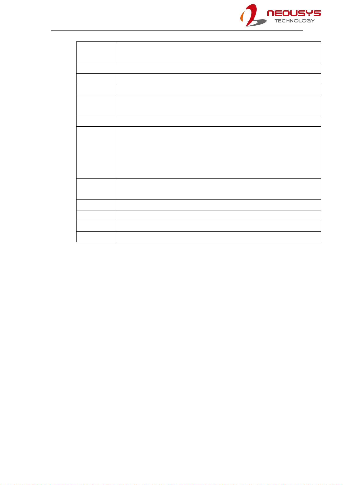
SEMIL-1700 Series
14
Max. Power
Consumption
Intel® Xeon® E-2278GE (max.TDP) - 108.96W(24V) - 114.24W(48V)
Intel® Xeon® E-2278GE (35 W) - 72.96W(24V) - 76.32W(48V)
Mechanical
Dimension
220mm (W) x 310mm (D) x 90.5mm (H)
Weight
5.8 kg
Mounting
Method
Rack-mount and wall-mount
Environmental
Operating
Temperature
With 35W CPU
-40°C ~ 70°C ***/ ****
With >= 65W CPU
-40°C ~ 70°C ***/ **** (configured as 35W TDP mode)
-40°C ~ 50°C ***/ **** (configured as 65W TDP mode)
Storage
Temperature
-40°C ~85°C
Humidity
10%~90% , non-condensing
Vibration
Operating, MIL-STD-810G, Method 514.7, Category 4
Shock
Operating, MIL-STD-810G, Method 516.7, Procedure I
EMC
EN-50155, CE/FCC Class A, according to EN 55032 & EN 55024
** For optional 10GbE support, please contact Neousys Technology
*** For Xeon E 2176G/ 2278GE, i7-9700E, and i7-8700 running at 65W mode, the highest
operating temperature shall be limited to 50°C and thermal throttling may occur when sustained
full-loading applied. Users can configure the CPU TDP in BIOS to obtain higher operating
temperature.
**** For sub-zero operating temperature, a wide temperature HDD or Solid State Disk (SSD) is
required.

SEMIL-1700 Series
15
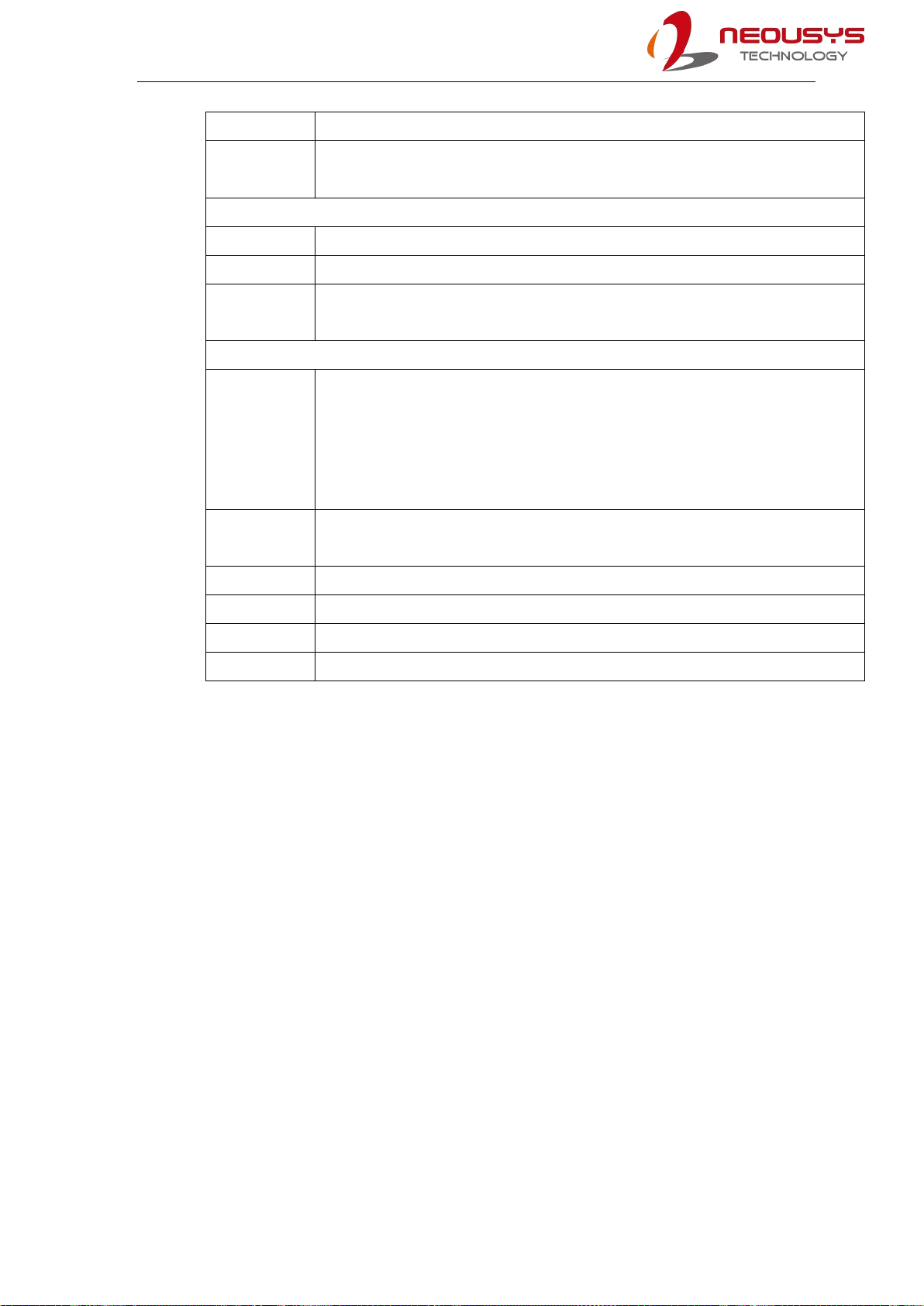
1.3 SEMIL-1708 Specifications
System Platform
Processor
Supporting Intel® Xeon® E and 9th/ 8th-Gen CPU (LGA1151 socket
- Xeon E 2176G (6C/12T) / 2278GE (8C/16T) / 2278GEL (8C/16T)
- Intel® Core™i7-9700TE/ i7-9700E/ i7-8700T/ i7-8700
- Intel® Core™i5-9500TE/ i5-9500E/ i5-8500T/ i5-8500
- Intel® Core™i3-9100TE/ i3-9100E/ i3-8100T/ i3-8100
Chipset
Intel® C246 platform
Graphics
Integrated Intel® HD Graphics 630
Memory
2x 260-pin SO-DIMM sockets, up to 64GB DDR4 2666/ 2400MHz SDRAM
AMT
Supports AMT 12.0
TPM
Supports TPM 2.0
I/O Interface
PoE+
1x IEEE 802.3at (25.5W) Gigabit PoE+ ports by Intel® I219 (M12 X-coded)
7x IEEE 802.3at (25.5W) Gigabit PoE+ ports by Intel® I210 (M12 X-coded)
10 GbE Port
(Build
Option)
Optional: 1x 10 GbE port by Intel® X550AT controller (M12 X-coded)**
Native Video
Port
1x VGA (M12 A-coded), supporting 1920 x 1200 resolution
Serial Port
2x 3-wire RS-232 ports COM1 & COM2 (M12 A-coded)
USB
4x USB 2.0 (M12 A-coded)
1x USB 2.0 (internal)
Audio
1x mic-in and speaker-out (M12 A-coded)
Storage Interface
SATA HDD
2x internal SATA ports for 2.5” HDD/ SSD installation, supporting RAID 0/ 1
mSATA
2x full-size mSATA ports (mux with mini-PCIe)
M.2
1x M.2 2280 M key socket (PCIe Gen3 x4) for NVMe SSD
or Intel® Optane™memory installation
Expansion Bus
Mini PCI-E
2x full-size mini PCI Express sockets (mux with mSATA)
2x full-size mini PCI Express sockets
Power Supply
DC Input
8 to 48V DC input (M12 S-coded)
Ignition
Built-in ignition power control (IGN/ GND signal via M12 serial port connector)
SEMIL-1700 Series
16
Control
Max. Power
Consumption
Intel® Xeon® E-2278GE (max.TDP) - 108.96W(24V) - 114.24W(48V)
Intel® Xeon® E-2278GE (35 W) - 72.96W(24V) - 76.32W(48V)
Mechanical
Dimension
220mm (W) x 310mm (D) x 90.5mm (H) (excluding rack-mount bracket)
Weight
5.9 kg
Mounting
Method
Rack-mount and wall-mount
Environmental
Operating
Temperature
With 35W CPU
-40°C ~ 70°C ***/ ****
With >= 65W CPU
-40°C ~ 70°C ***/ **** (configured as 35W TDP mode)
-40°C ~ 50°C ***/ **** (configured as 65W TDP mode)
Storage
Temperature
-40°C ~85°C
Humidity
10%~90% , non-condensing
Vibration
Operating, MIL-STD-810G, Method 514.7, Category 4
Shock
Operating, MIL-STD-810G, Method 516.7, Procedure I
EMC
EN-50155, CE/FCC Class A, according to EN 55032 & EN 55024
** For optional 10GbE support, please contact Neousys Technology
*** For Xeon E 2176G/ 2278GE, i7-9700E, and i7-8700 running at 65W mode, the highest
operating temperature shall be limited to 50°C and thermal throttling may occur when sustained
full-loading applied. Users can configure the CPU TDP in BIOS to obtain higher operating
temperature.
**** For sub-zero operating temperature, a wide temperature HDD or Solid State Disk (SSD) is
required.

SEMIL-1700 Series
17
1.4 SEMIL-1714J Specifications
System Platform
Processor
Supporting Intel® Xeon® E and 9th/ 8th-Gen CPU (LGA1151 socket
- Xeon E 2176G (6C/12T) / 2278GE (8C/16T) / 2278GEL (8C/16T)
- Intel® Core™i7-9700TE/ i7-9700E/ i7-8700T/ i7-8700
- Intel® Core™i5-9500TE/ i5-9500E/ i5-8500T/ i5-8500
- Intel® Core™i3-9100TE/ i3-9100E/ i3-8100T/ i3-8100
Chipset
Intel® C246 platform
Graphics
Integrated Intel® HD Graphics 630
Memory
2x 260-pin SO-DIMM sockets, up to 64GB DDR4 2666/ 2400MHz SDRAM
AMT
Supports AMT 12.0
TPM
Supports TPM 2.0
I/O Interface
PoE+
1x IEEE 802.3at (25.5W) Gigabit PoE+ ports by Intel® I219 (M12 X-coded)
3x IEEE 802.3at (25.5W) Gigabit PoE+ ports by Intel® I210 (M12 X-coded)
10 GbE Port
(Build
Option)
Optional: 1x 10 GbE port by Intel® X550AT controller (M12 X-coded)**
Native Video
Port
1x VGA (M12 A-coded), supporting 1920 x 1200 resolution
Serial Port
2x 3-wire RS-232 ports COM1 & COM2 (M12 A-coded)
USB
2x USB 2.0 (M12 A-coded)
1x USB 2.0 (internal)
Audio
NA
Storage Interface
SATA HDD
2x internal SATA ports for 2.5” HDD/ SSD installation, supporting RAID 0/ 1
mSATA
2x full-size mSATA ports (mux with mini-PCIe)
M.2
1x M.2 2280 M key socket (PCIe Gen3 x4) for NVMe SSD
or Intel® Optane™memory installation
Expansion Bus
Mini PCI-E
2x full-size mini PCI Express sockets (mux with mSATA)
Power Supply
DC Input
8 to 48V DC input (M12 S-coded)
Ignition
Control
Built-in ignition power control
(IGN/ GND signal via M12 serial port connector)
SEMIL-1700 Series
18
Power Backup
Capacity
2500 watt-second
Max. Power
Consumption
Intel® Xeon® E-2278GE (max.TDP) - 108.96W(24V) - 114.24W(48V)
Intel® Xeon® E-2278GE (35 W) - 72.96W(24V) - 76.32W(48V)
Mechanical
Dimension
440mm (W) x 310mm (D) x 90.5mm (H) (excluding rack-mount bracket)
Weight
6 kg
Mounting
Method
Rack-mount and wall-mount
Environmental
Operating
Temperature
With 35W CPU
-40°C ~ 70°C ***/ ****
With >= 65W CPU
-40°C ~ 70°C ***/ **** (configured as 35W TDP mode)
-40°C ~ 50°C ***/ **** (configured as 65W TDP mode)
Storage
Temperature
-40°C ~85°C
Humidity
10%~90% , non-condensing
Vibration
Operating, MIL-STD-810G, Method 514.7, Category 4
Shock
Operating, MIL-STD-810G, Method 516.7, Procedure I
EMC
EN-50155, CE/FCC Class A, according to EN 55032 & EN 55024
** For optional 10GbE support, please contact Neousys Technology
*** For Xeon E 2176G/ 2278GE, i7-9700E, and i7-8700 running at 65W mode, the highest
operating temperature shall be limited to 50°C and thermal throttling may occur when sustained
full-loading applied. Users can configure the CPU TDP in BIOS to obtain higher operating
temperature.
**** For sub-zero operating temperature, a wide temperature HDD or Solid State Disk (SSD) is
required.

SEMIL-1700 Series
19
1.5 SEMIL-1718J Specifications
System Platform
Processor
Supporting Intel® Xeon® E and 9th/ 8th-Gen CPU (LGA1151 socket
- Xeon E 2176G (6C/12T) / 2278GE (8C/16T) / 2278GEL (8C/16T)
- Intel® Core™i7-9700TE/ i7-9700E/ i7-8700T/ i7-8700
- Intel® Core™i5-9500TE/ i5-9500E/ i5-8500T/ i5-8500
- Intel® Core™i3-9100TE/ i3-9100E/ i3-8100T/ i3-8100
Chipset
Intel® C246 platform
Graphics
Integrated Intel® HD Graphics 630
Memory
2x 260-pin SO-DIMM sockets, up to 64GB DDR4 2666/ 2400MHz SDRAM
AMT
Supports AMT 12.0
TPM
Supports TPM 2.0
I/O Interface
PoE+
1x IEEE 802.3at (25.5W) Gigabit PoE+ ports by Intel® I219 (M12 X-coded)
7x IEEE 802.3at (25.5W) Gigabit PoE+ ports by Intel® I210 (M12 X-coded)
10 GbE Port
(Build
Option)
Optional: 1x 10 GbE port by Intel® X550AT controller (M12 X-coded)**
Native Video
Port
1x VGA (M12 A-coded), supporting 1920 x 1200 resolution
Serial Port
2x 3-wire RS-232 ports COM1 & COM2 (M12 A-coded)
USB
2x USB 2.0 (M12 A-coded)
1x USB 2.0 (internal)
Audio
1x mic-in and speaker-out (M12 A-coded)
Storage Interface
SATA HDD
2x internal SATA ports for 2.5” HDD/ SSD installation, supporting RAID 0/ 1
mSATA
2x full-size mSATA ports (mux with mini-PCIe)
M.2
1x M.2 2280 M key socket (PCIe Gen3 x4) for NVMe SSD
or Intel® Optane™memory installation
Expansion Bus
Mini PCI-E
2x full-size mini PCI Express sockets (mux with mSATA)
2x full-size mini PCI Express sockets
Power Supply
DC Input
8 to 48V DC input (M12 S-coded)
Ignition
Built-in ignition power control (IGN/ GND signal via M12 serial port connector)
SEMIL-1700 Series
20
Control
Power Backup
Capacity
2500 watt-second
Max. Power
Consumption
Intel® Xeon® E-2278GE (max.TDP) - 108.96W(24V) - 114.24W(48V)
Intel® Xeon® E-2278GE (35 W) - 72.96W(24V) - 76.32W(48V)
Mechanical
Dimension
220mm (W) x 310mm (D) x 90.5mm (H) (excluding rack-mount bracket)
Weight
6.2 kg
Mounting
Method
Rack-mount and wall-mount
Environmental
Operating
Temperature
With 35W CPU
-40°C ~ 70°C ***/ ****
With >= 65W CPU
-40°C ~ 70°C ***/ **** (configured as 35W TDP mode)
-40°C ~ 50°C ***/ **** (configured as 65W TDP mode)
Storage
Temperature
-40°C ~85°C
Humidity
10%~90% , non-condensing
Vibration
Operating, MIL-STD-810G, Method 514.7, Category 4
Shock
Operating, MIL-STD-810G, Method 516.7, Procedure I
EMC
EN-50155, CE/FCC Class A, according to EN 55032 & EN 55024
** For optional 10GbE support, please contact Neousys Technology
*** For Xeon E 2176G/ 2278GE, i7-9700E, and i7-8700 running at 65W mode, the highest
operating temperature shall be limited to 50°C and thermal throttling may occur when sustained
full-loading applied. Users can configure the CPU TDP in BIOS to obtain higher operating
temperature.
**** For sub-zero operating temperature, a wide temperature HDD or Solid State Disk (SSD) is
required.
Table of contents
Other Neousys Industrial PC manuals


Popular Industrial PC manuals by other brands


Dell
Dell Embedded Box PC 5000 Installation and operation manual

IBASE Technology
IBASE Technology ASB200-918 Series user manual

Lenovo
Lenovo ThinkCentre M90q Hardware Maintenance Manual

IXXAT
IXXAT Econ 100 Hardware manual

Kontron
Kontron KBox A-151-TGL user guide

AXIOMTEK
AXIOMTEK ICO500-518 Series user manual