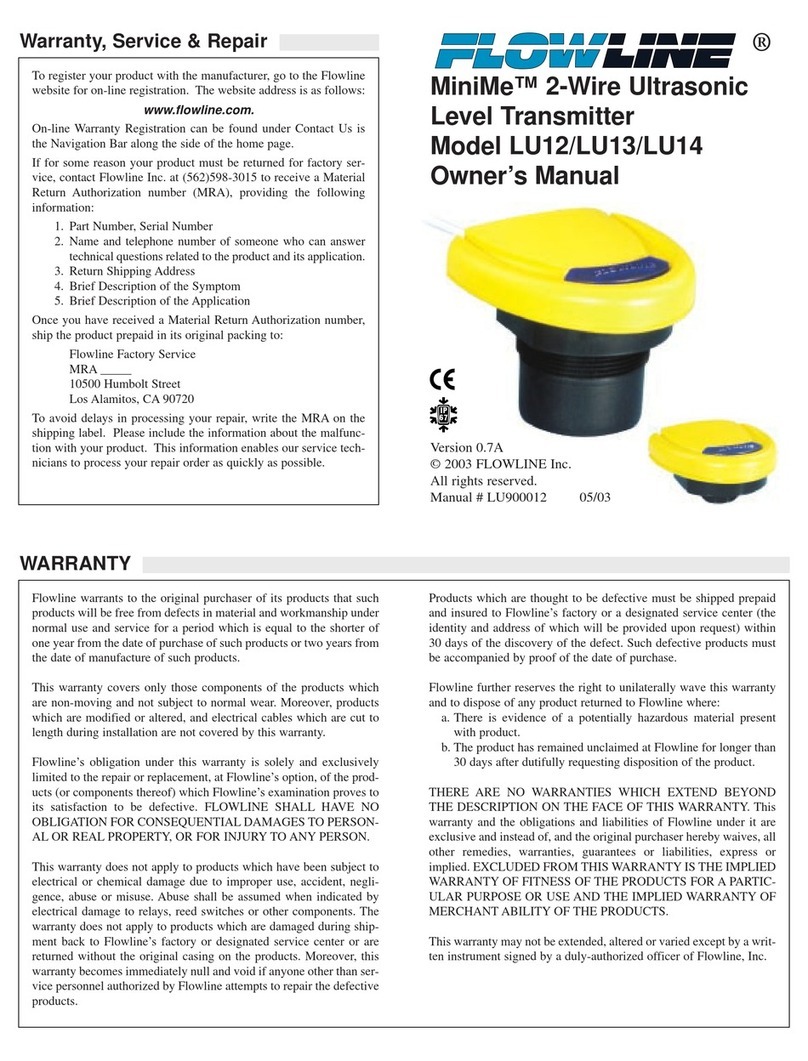
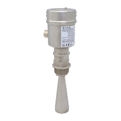
FlowLine EchoSafe XP88 User manual
Other FlowLine Transmitter manuals
FlowLine
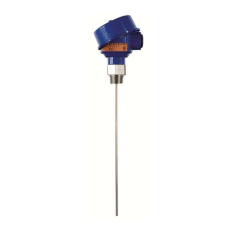
FlowLine EchoWave LG11 Series User manual
FlowLine
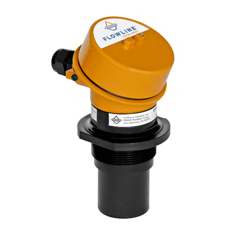
FlowLine EchoTouch US12 Series User manual
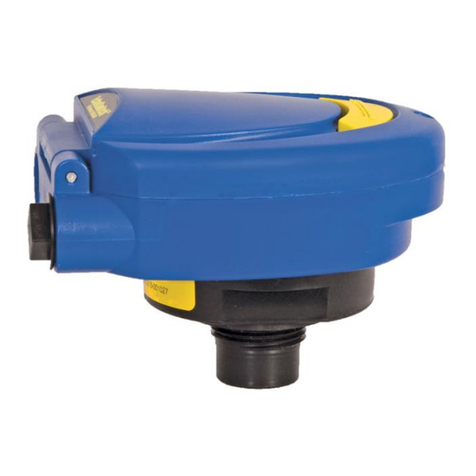
FlowLine
FlowLine EchoSpan LU80-5101 User manual
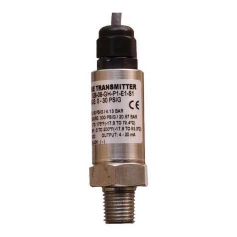
FlowLine
FlowLine DeltaSpan LD30 Series User manual
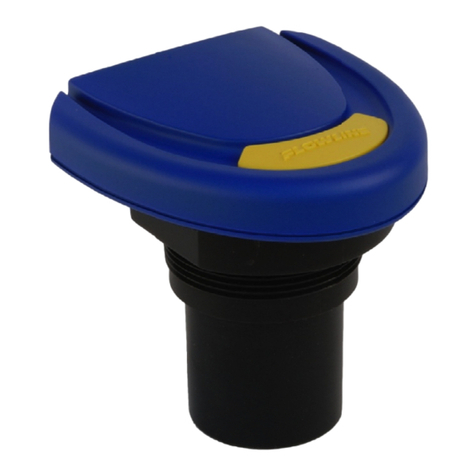
FlowLine
FlowLine EchoSonic LU23 Series User manual
FlowLine
FlowLine EchoBeam LR83 Series User manual
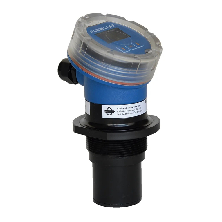
FlowLine
FlowLine EchoPod UG06 Series User manual
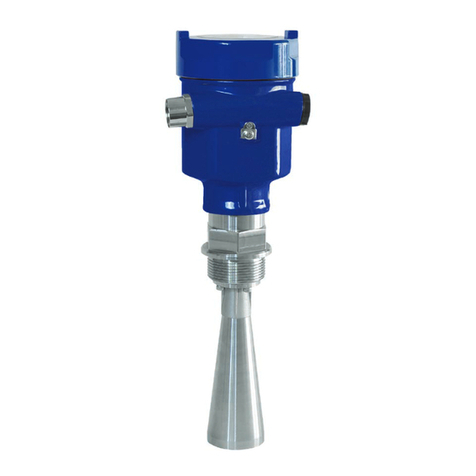
FlowLine
FlowLine EchoPulse LR10 Series User manual
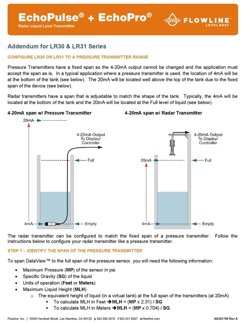
FlowLine
FlowLine EchoPulse LR30 Series User manual
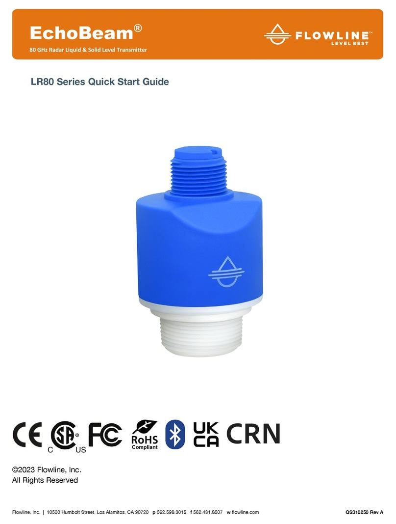
FlowLine
FlowLine EchoBeam LR80 Series User manual

FlowLine
FlowLine Ricochet LA15 User manual
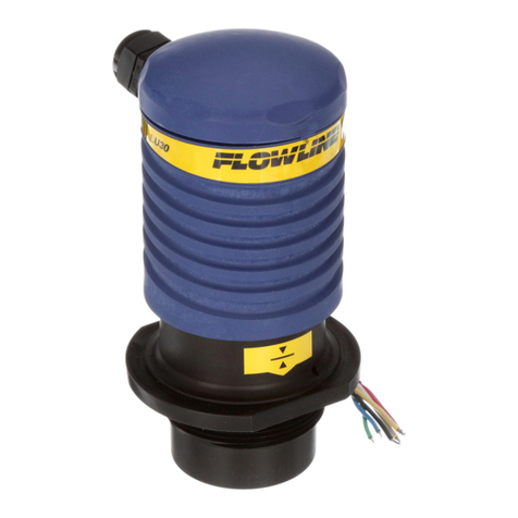
FlowLine
FlowLine LU30 User manual
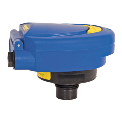
FlowLine
FlowLine EchoSonic II LU27 Series User manual
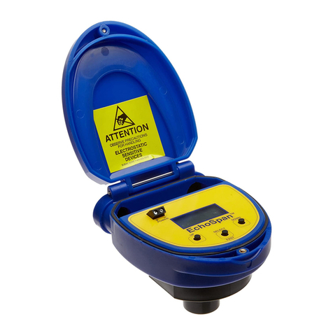
FlowLine
FlowLine EchoSpan LU80 series User manual
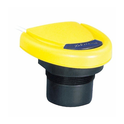
FlowLine
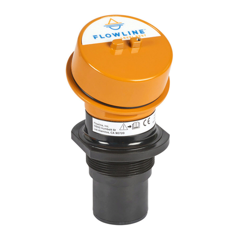
FlowLine EchoSonic LU05 User manual
FlowLine
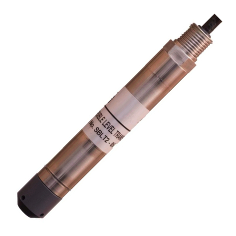
FlowLine EchoTouch US01 Series User manual
FlowLine
FlowLine LD31-S301 Series User manual

FlowLine
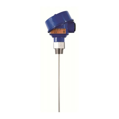
FlowLine EchoPod DL34 Series User manual
FlowLine
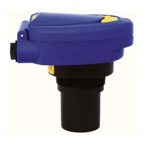
FlowLine EchoWave LG10 Series User manual
FlowLine
FlowLine EchoSonic II Series User manual
Popular Transmitter manuals by other brands

Dejero
Dejero EnGo 3x manual

Rosemount
Rosemount 4600 Reference manual

Speaka Professional
Speaka Professional 2342740 operating instructions

trubomat
trubomat GAB 1000 instruction manual

Teledyne Analytical Instruments
Teledyne Analytical Instruments LXT-380 instructions

Rondish
Rondish UT-11 quick start guide
