12
H
B
P
L
I
GB
F
D
E
(
CM
,
GG
PP
T
I
GB
F
D
E
1)IldisegnodiFig.A,mostralasezionediunplintoperpaliconmuratura.Nelcentrodelplintovàrealizzatounforocondimensioni(B,Ø)idoneeall’inserimentodell’anima
delpalo,la tabellaa pag.8 riportatuttele dimensioni(altezza ediametro) delleanimepali conmuratura. Ildiametro (Ø)delforo ricavatonel plintodovrà esserecirca
10 cm superiore al diametro della muratura dell’anima da installare. Predisporre un tubo essibile ( G, diametro interno cm 2) e un altro (P, diametro interno cm 5)
in PVC, per il passaggio dei cavi elettrici dal pozzetto di derivazione all’anima. 2) Il disegno di Fig. B, mostra la sezione di un plinto per pali con angia. Nel centro del
plinto vànno annegati i tirafondi (T), i disegni a pag. 9 e 14 riportano tutte le informazioni (fori, diametri, interassi) per il posizionamento. I tirafondi (T) devono essere
posizionati 5 cm più alti rispetto al piano del plinto, e devono avere la parte sporgente filettata. Predisporre un tubo essibile ( G, diametro interno cm 5) in PVC,
per il passaggio dei cavi elettrici dal pozzetto di derivazione all’anima, da posizionare al centro fra i tirafondi e un altro (P, diametro interno cm 2) per il cavo di massa.
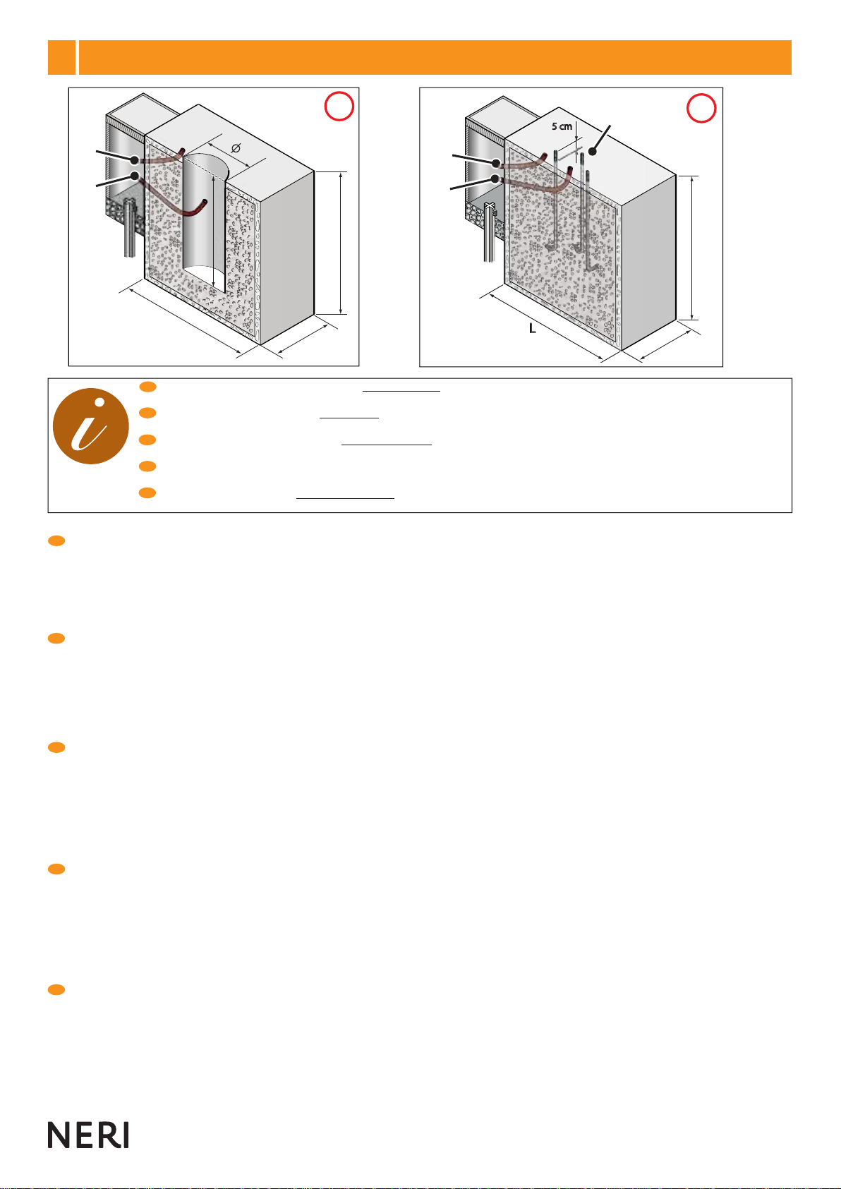
1) The drawing in Fig. Ashows the cross section of a plinth for cores to be cemented in. At the centre of the plinth there should be a hole (dimensions B,
Ø) suitable for insertion of the core. The chart on page 8 shows the relative dimensions (height and diameter) for all cores for cementing in. The hole
in the plinth should have diameter (Ø) at least 10 cm greater than the diameter of the base of the core to be installed. Prepare a exible PVC tube ( G, inside
diameter 2 cm) and a second one (P, inside diameter 5 cm) for the passage of the electrical cables from the branch box to the core. 2) The drawing in Fig. B
shows the cross section of a plinth for cores with anges. Anchor bolts ( T) must be sunk into the centre of the plinth; the drawings on pages 9 and 14 give all
the relative information (holes, diameters, centre distances) for positioning of the anchor bolts. The anchor bolts (T) must be positioned 5 cm higher than the
plinth level, and the protruding sections must be threaded. Prepare a exible PVC tube ( G, inside diameter 5 cm) for the passage of electrical cables from
the branch box to the core, to be positioned at the centre between the anchor bolts, and prepare a second tube (P, inside diameter 2 cm) for the earth cable.
1)LedessindelaFig.A,montrelasectiond’unplinthepourdescandélabresàscellementdirect.Letrouàréaliseraucentreduplinthedoitavoirdesdimensions(B,Ø)
appropriéespourl’introductiondel’âmeducandélabre,letableauàpage8reportetouteslesdimensions(hauteuretdiamètre)desâmesdescandélabresàscellement
direct.Lediamètre(Ø)dutroupratiquédansleplinthedevraêtred’environ10cmsupérieuraudiamètreduscellementdel’âmeàinstaller.Prévoiruntubeexible
(G,diamètreinterne2cm)etunautre(P,diamètreinterne5cm)enPVC,pourlepassagedescâblesélectriquesdelachambrededérivationàl’âme.2)Ledessindela
Fig.B,montrelasectiond’unplinthepourdescandélabresavecbride.Letrouàréaliseraucentreduplinthedoitêtreprofond10cmetavoirundiamètreappropriépour
l’introductiondelaBride(voirdessinpage 9)UNIQUEMENTpourlescandélabresdutableau(Fig.B).Lestire-fond(T)doiventêtrenoyéstoujoursaucentreduplinthe,
les dessins aux pages 9 et 14 reportent toutes les informations (trous, diamètres, entraxes) pour le positionnement correct. Les tire-fond (T) doivent être positionnés
5 cm plus hauts par rapport au niveau du plinthe et leur partie saillante doit être filetée. Prévoir un tube exible ( G, diamètre interne 5 cm) en PVC, pour le passage
des câbles électriques de la chambre de dérivation à l’âme, à positionner au centre entre les tire-fond et un autre (P, diamètre interne 2 cm) pour le câble de masse.
1) Die Zeichnung von Abb. A zeigt den Querschnitt eines Sockels für einzumauernde Masten. Der Sockel muss im Zentrum mit einem Loch mit den
Abmessungen (B,Ø) versehen werden, in das das Mastrohr eingesetzt werden kann. Die Tabelle auf S. 8 enthält alle Maßangaben (Höhe und Durchmesser)
der einzumauendern Mastrohre. Der Durchmesser (Ø) des Lochs im Sockel muss ca. 10 größer als der Einmauerungsdurchmesser des zu montierenden
Mastrohrs sein. Ein exibles Installationsrohr (G, Innendurchmesser 2 cm) und ein weiteres Installationsrohr ( P, Durchmesser 5 cm) aus PVC für die
Verlegung der Stromkabel vom Abzweigschacht zum Mastrohr vorsehen. 2) Die Zeichnung von Abb. Bzeigt den Querschnitt eines Sockels für Masten mit
Flansch. Im Zentrum des Sockels müssen die Ankerbolzen (T) eingelassen werden. Die Zeichnungen auf S. 9 und 14 enthalten alle für die Positionierung
erforderlichen Informationen (Löcher, Durchmesser, Achsabstände). Der gewindete Teil der Ankerbolzen (T) muss 5 cm aus der Oberseite des
Sockels herausragen. Ein exibles Installationsrohr ( G, Innendurchmesser 5 cm) aus PVC für die Verlegung der Stromkabel vom Abzweigschacht
zum Mastrohr im Zentrum der Ankerbolzen anordnen. Ein weiteres Installationsrohr (P, Innendurchmesser 2 cm) für das Erdungskabel vorsehen.
1) El dibujo de la Fig. Amuestra la sección de un plinto para postes con mampostería. En el centro del plinto se debe realizar un orificio de dimensiones
adecuadas (B,Ø) para introducir el alma del poste. En la tabla de la pág. 8 se indican todas las medidas (altura y diámetro) de las almas de postes con
mampostería. El diámetro (Ø) del orificio realizado en el plinto debe ser unos 10 cm más grande que el diámetro de la mampostería del ánima que se ha de
instalar. Colocar un tubo exible (G, diámetro interno 2 cm) y un tubo (P, diámetro interno 5 cm) de PVC para hacer pasar los cables desde la caja de derivación
al alma. 2) El dibujo de la Fig. B, muestra la sección de un plinto para postes con brida. Sumergir los tirafondos (T) en el plinto. Consultar las figuras de las
págs. 9 y 14 para conocer las medidas de instalación (orificios, diámetros y distancias entre ejes). El extremo roscado de los tirafondos (T) debe sobresalir 5
cm por encima de la superficie del plinto. Colocar un tubo exible ( G, diámetro interno cm 5) de PVC en el centro de los tirafondos para hacer pasar los cables
eléctricos desde la caja de derivación al alma en el centro de los tirafondos y un segundo tubo (P, diámetro interno cm 2) para hacer pasar el cable de masa.
Per realizzare il plinto devono essere forniti dal direttore dei lavori i seguenti dati: dimensioni (L,P,H,); dosaggio del calcestruzzo; ferri per l’armatura
interna; dimensione e tipo dei tirafondi (non forniti).
For the construction of the plinth the clerk of works must provide the following information: dimensions (L, P, H); concrete mix proportions; steel
bars for internal reinforcement; dimensions and type of anchor bolts (not supplied).
Pour la réalisation du massif d’ancrage, le directeur des travaux doit fournir les données suivantes: dimensions (L, P, H); dosage du béton; fers à
béton; dimension et type de tire-fond (non fournis).
Zur Anfertigung des Fundamentsockels müssen vom Verantwortlichen für die Arbeiten die folgenden Daten geliefert werden: Dimensionen (H, T, B);
Dosierung der Zementmischung; Armierungseisen; Dimensionen und Typ der Bodenbefestigungseisendübel (werden nicht geliefert).
Para realizar el plinto o base, el director de los trabajos debe proporcionar los datos siguientes: dimensiones (L, P, H); dosis de hormigón, hierros
para el armado interno; dimensiones y tipo de los tirafondos (no suministrados de fábrica).
8° PLINTO DI FONDAZIONE - CROSS SECTION - MASSIF D’ANCRAGE
FUNDAMENTSOCKEL - PLINTO DE CIMENTACIÓN