manuals.online logo
Brands
  1. Home
  2. •
  3. Brands
  4. •
  5. NERI
  6. •
  7. Outdoor Light
  8. •
  9. NERI LIGHT 104 User manual

NERI LIGHT 104 User manual

I
GB
F
D
E
Rev. A - 08/2014
ATTENZIONE - CAUTION
ATTENTION - ACHTUNG
ATENCIÓN
Questo manuale va letto
e conservato con molta attenzione
This manual should be read with
attention and kept with great care
Ce manuel doit être lu très
attentivement et soigneusement
conservé
Die Anleitung sollte mit großer
Aufmerksamkeit gelesen und
aufbewahrt werden
Este manual se debe leer con
detenimiento y conservar
cuidadosamente
LIBRETTO ISTRUZIONI
APPARECCHI
DI ILLUMINAZIONE
INSTRUCTION BOOKLET
LIGHT FIXTURES
NOTICE DE MONTAGE
LUMINAIRES
INSTALLATIONSANLEITUNG
BELEUCHTUNGSAPPARATE
MANUAL DE
INSTRUCCIONES DE
DISPOSITIVOS DE
ALUMBRADO
I
GB
F
D
E
LIGHT 104
for discharge lamps
2 3
Autori: Isacco Neri - Titolo: Libretto istruzioni apparecchi di illuminazione - Pubblicatore: Neri spa
Progetto e coordinamento graco: Daniele Lombardi - Stampa: Grache MDM s.r.l., Forlì FC, Agosto 2014.
Tutti i diritti riservati. E’ fatto espresso divieto a qualunque riproduzione parziale o totale del presente testo.
DESIGN PATENTED, PRINTED IN ITALY
NERI S.p.A
S.S. Emilia 1622 - 47020 Longiano (FC) - Italy
Tel. +39 0547 652111 Fax +39 0547 54074
www.neri.biz - [email protected]
Ogni riproduzione ed utilizzo per ni propri di questo manuale non è consentita.
Tutti i diritti sono riservati.
E’ vietata la riproduzione anche parziale di esso senza il consenso scritto della Neri spa.
La Neri spa si riserva il diritto di apportare modiche ai propri prodotti e alla documentazione senza obbligo di preavviso.
Any reproduction and use for its own purposes of this manual is not permitted.
All rights reserved.
Reproduction of this manual, even partially, is forbidden without written consent from Neri spa.
Neri spa reserves the right to modify its products and documentation without obligation to give prior warning.
Toute reproduction et utilisation pour ses propres ns de ce manuel n’est pas autorisée.
Tous droits réservés.
Ce manuel ne peut être reproduit, même partiellement, sans l’accord écrit de Neri spa.
Neri spa se réserve le droit d’apporter toutes modications à ses produits et à la documentation sans préavis.
Eine Vervielfältigung und Nutzung für den eigenen Zweck dieses Handbuches ist nicht gestattet.
Alle Rechte vorbehalten.
Seine - auch auszugsweise - Reproduktion ohne schriftliche Zustimmung der Neri spa ist verboten.
Die Neri spa behält sich das Recht vor, an ihren Produkten und der Dokumentation Veränderungen vorzunehmen, ohne
dies vorher ankündigen zu müssen.
Cualquier reproducción y uso para sus propios nes de este manual no está permitido.
Todos los derechos reservados.
Se prohíbe su reproducción incluso parcial sin autorización por escrito de la empresa Neri spa.
Neri spa se reserva el derecho de aportar cambios a sus productos y a la documentación sin obligación de
aviso previo.
3www. neri.biz
INDICE - CONTENTS - INDEX - INHALTVERZEICHNIS - INDICE
INSTALLAZIONE
INSTALLATION
FIXATION
SOCKEL
ENGANCHE
pag 10-13
6°
I
GB
F
D
E
OTTICHE
REFLECTOR
OPTIK
ELEMENTE
REFLECTORES
pag 15
8°
I
GB
F
D
E
DESTINAZIONE D’USO
INTENDED USE
UTILISATION DES LUMINAIRES
ZWECKBESTIMMUNG
UTILIZACIÓN
pag 20
12°
I
GB
F
D
E
GARANZIA
GARANTEE
GARANTIE
GARANTIE
GARANTIA
pag 20
13°
I
GB
F
D
E
SMALTIMENTO
DISPOSAL
MISE AU REBUT
ENTSORGUNG
RECICLADO
pag 21
14°
I
GB
F
D
E
MANUTENZIONE
MAINTENANCE
ENTRETIEN
WARTUNG
MANTENIMIENTO
pag 23
16°
I
GB
F
D
E
RICAMBI
SPARE PARTS
PIÈCES DE RECHANGE
ERSATZTEILE
RECAMBIOS
pag 22
15°
I
GB
F
D
E
SOSTITUZIONE FUSIBILE
FUSE REPLACEMENTS
REPLACEMENT DU FUSIBILE
AUSTAUSCH DER SICHERUNG
SUSTITUCIÓN DEL FUSIBLE
pag 14
7°
I
GB
F
D
E
CARATTERISTICHE
CHARACTERISTICS
CARACTERISTIQUES
EIGENSCHAFTEN
CARACTERISTÌCAS
pag 18
10°
I
GB
F
D
E
AVVERTENZE PER L’INSTALLAZIONE
INSTALLATION INFORMATION
PRECAUTIONS POUR L’INSTALLATION
INSTALLATIONSANLEITUNG
ADVERTENCIAS PARA INSTALACIÓN
pag 16-17
9°
I
GB
F
D
E
ORIENTAMENTO OTTICA ASIMMETRICA
ASYMMETRICAL REFLECTOR POSITIONING
ORIENTATION DU RéFLECTEUR ASYMéTRIQUE
ASYMETRISCHER REFLEKTOR AUSRIGHTUNG
ORIENTACIÓN DEL REFLECTOR ASIMéTRICO
11°
I
GB
F
D
E
pag 19
pag 5
1°
I
GB
F
D
E
NOTE GENERALI ALLA CONSEGNA
DELIVERY INFORMATION
NOTES GENERALES POUR LA LIVRAISON
ALLGEMEINE ANMERKUNGEN ZUR ANLIEFERUNG
NOTAS GENERALES A LA ENTREGA
SIMBOLI
SYMBOLS
SYMBOLES
SYMBOLE
SÍMBOLOS
pag 6
2°
I
GB
F
D
E
ETICHETTE
LABELS
ETIQUETTE
AUFKLEBER
ETIQUETAS
pag 7
3°
I
GB
F
D
E
PRESCRIZIONI DI SICUREZZA
SAFETY PRECAUTIONS
PRESCRIPTIONS DE SECURITE
SICHERHEITSVORSCHRIFTEN
NORMAS DE SEGURIDAD
pag 8
4°
I
GB
F
D
E
DISIMBALLO
UNPACKING
DEBALLAGE
AUSPACKEN
DESEMBALAJE
5°
I
GB
F
D
E
pag 9
45
Certicato/Certicate
9105.DONE
ISO 9001:2008
Certicato/Certicate
9191.NER1
ISO 14001:2004
I
GB
F
D
E
La Neri spa è impegnata costantemente nella ricerca e progettazione di prodotti di alta qualità, lunga durata e sicurezza.
Questo manuale intende presentare le metodiche di installazione corrette dei corpi illuminanti, ponendosi come guida nei
confronti di installatori professionali. A tale scopo questo manuale va letto e conservato con molta attenzione.
Neri S.p.A is constantly committed to research and design for products of high quality, durability and safety.
This manual aims to present correct installation procedures for light xtures as a guide for professional installers.
To this end the manual should be read and preserved with extreme attention.
Neri spa a toujours eu pour objectif la recherche et la conception de produits de haute qualité, offrant longévité et sécurité.
Ce manuel, qui présente les modes d’installation corrects des armatures d’éclairage, est un guide à l’adresse des
installateurs professionnels. Il doit donc être lu très attentivement et conservé.
Die Neri spa ist konstant um Forschung und Entwicklung zeitbeständiger und sicherer Produkte von hoher Qualität
bemüht. Dieses Handbuch stellt die korrekten Installationsmethoden für die Leuchtkörper bereit und bietet sich gegenüber
professionellen Installateuren als ein Ratgeber an. Deswegen sollte dies Handbuch sehr aufmerksam gelesen werden
und konserviert.
La empresa Neri spa trabaja de continuo en el estudio y proyección de productos de alta calidad, larga duración y
seguridad. Este manual presentará los métodos de instalación correcta de los cuerpos de iluminación, siendo una guía
para instaladores profesionales. Por ello, este manual debe leerse con gran detenimiento y preservado.
INTRODUZIONE - INTRODUCTION - INTRODUCTION - EINLEITUNG - INTRODUCCIÓN
5www. neri.biz
A
I
GB
F
D
E
1° NOTE GENERALI ALLA CONSEGNA - DELIVERY INFORMATION - NOTES GENERALES
POUR LA LIVRAISON - ALLGEMEINE ANMERKUNGEN ZUR ANLIEFERUNG - NOTAS
GENERALES A LA ENTREGA
Gli apparecchi per illuminazione possono essere spediti esclusivamente in scatole di cartone (Fig. A) in varie dimensioni.
In ogni caso comunque al ricevimento della merce controllare che:
1) l’imballo sia integro;
2) la fornitura corrisponda all’ordine (vedi bolla di consegna);
3) non vi siano parti mancanti.
In caso di danni o parti mancanti, informare immediatamente e in modo dettagliato (foto) la Neri spa.
The light xture can be shipped and delivered only in cardboard boxes (Fig. A) of various sizes.
On receipt of the goods, always:
1) check that packing is undamaged;
2) check that goods received correspond to order (consult delivery note);
3) check that there are no missing parts.
In case of damage or missing parts, immediately inform Neri spa, giving full details (photo).
Les luminaires ne peuvent être expédiés qu’emballés dans des boîtes en carton (Fig. A) de dimensions diverses.
Quoi qu’il en soit, dès la réception de la marchandise, s’assurer que:
1) l’emballage soit intact;
2) la fourniture corresponde à la commande (voir bulletin de livraison);
3) il ne manque aucune partie.
En cas de dommages ou de parties manquantes, informer immédiatement d’une manière détaillée (photo)Neri spa.
Die Beleuchtungsapparate werden ausschließlich in Pappkartons (Abb. A) unterschiedlicher Größe versandt Jedenfalls
muss man beim Wareneingang stets kontrollieren, dass:
1) die Verpackung unversehrt ist;
2) die Lieferung der Bestellung entspricht (siehe Lieferschein);
3) keine Teile fehlen.
Bei Schäden oder fehlenden Teilen sofort und detailliert (mit Foto) die Neri spa informieren.
Los aparatos de alumbrado se pueden enviar sólo en cajas de cartón (Fig. A) de varios tamaños.
De todos modos al recibir la mercancía controlen:
1) que el embalaje esté íntegro;
2) que el suministro corresponda al pedido (vean albarán);
3) que no falten piezas.
En caso de daños o piezas que falten, informen a Neri spa de inmediato y con detalles (foto).
6 7
Fig. 1 Fig. 9Fig. 8Fig. 7Fig. 6Fig. 5Fig. 4Fig. 3Fig. 2
I
GB
F
D
E
I simboli mostrati sopra hanno il seguente signicato:
Fig. 1 > ABBIGLIAMENTO DA LAVORO
Fig. 2 > SCARPE ANTINFORTUNISTICHE
Fig. 3 > CASCO OBBLIGATORIO
Fig. 4 > GUANTI DA LAVORO
Fig. 5 > PERICOLO PER L’OPERATORE
Fig. 6 > DANNI AI COMPONENTI
Fig. 7 > INQUINAMENTO AMBIENTALE
Fig. 8 > NOTA INFORMATIVA
Fig. 9 > VERIFICA TECNICA.
The symbols shown above have the following meanings:
Fig. 1 > WORK APPARE
Fig. 2 > SAFETY SHOES
Fig. 3 > OBLIGATORY HELMET
Fig. 4 > WORK GLOVES
Fig. 5 > DANGER FOR THE OPERATOR
Fig. 6 > DAMAGE TO COMPONENTS
Fig. 7 > ENVIRONMENTAL POLLUTION
Fig. 8 > INFORMATIVE NOTE
Fig. 9 > TECHNICAL CHECK.
Les symboles indiqués aux signications suivantes:
Fig. 1 > VÊTEMENTS DE TRAVAIL
Fig. 2 > CHAUSSURES DE SÉCURITÉ
Fig. 3 > CASQUE OBLIGATOIRE
Fig. 4 > GANTS DE TRAVAIL
Fig. 5 > DANGER POUR L’OPÉRATEUR
Fig. 6 > DOMMAGES AUX COMPOSANTS
Fig. 7 > POLLUTION DE L’ENVIRONNEMENT
Fig. 8 > NOTE D’INFORMATION
Fig. 9 > VÉRIFICATION TECHNIQUE.
Die oben gezeigten Symbole haben folgende Bedeutung:
Abb. 1 > ARBEITSKLEIDUNG
Abb. 2 > SCHUTZSCHUHE
Abb. 3 > HELMPFLICHT
Abb. 4 > ARBEITSHANDSCHUHE
Abb. 5 > GEFAHR FÜR DEN TECHNIKER
Abb. 6 > SCHÄDEN AN DEN KOMPONENTEN
Abb. 7 > UMWELTVERSCHMUTZUNG
Abb. 8 >INFORMATIONSBLATT
Abb. 9 > TECHNISCHE KONTROLLE.
Los símbolos mostrados arriba tienen el siguiente signicado:
Fig. 1 > ROPA DE TRABAJO OBLIGATORIA
Fig. 2 > CALZADO DE SEGURIDAD OBLIGATORIO
Fig. 3 > CASCO DE SEGURIDAD OBLIGATORIO
Fig. 4 > GUANTES DE SEGURIDAD OBLIGATORIOS
Fig. 5 > PELIGRO PARA EL OPERADOR
Fig. 6 > DAÑOS A LOS COMPONENTES
Fig. 7 > CONTAMINACIÓN DEL MEDIO AMBIENTE
Fig. 8 > NOTA INFORMATIVA
Fig. 9 > COMPROBACIÓN TÉCNICA.
SIMBOLI - SYMBOLS - SYMBOLES - SYMBOLE - SÍMBOLOS
2°
7www. neri.biz
ATTENZIONE
Accenditore con impulso di
innesco ..... KV.
Installare solo lampade
compatibili al tipo di impulso.
ATTENTION
Igniter with starting impulse
...... KV. Install only lamps
compatible with this impulse type.
Ogni elemento è contrassegnato da una etichetta adesiva posta sull’imballo.
Vi sono riportati il codice e una breve descrizione, due dati basilari con cui è possibile identicarlo.
Etichette adesive di avvertimento e indicazione sono poste sull’apparecchio e l’installatore deve scrupolosamente
seguirne le indicazioni. Vi possono essere indicazioni sul posizionamento dell’apparecchio rispetto alla carreggiata
stradale (g.A-B), indicazioni sulle caratteristiche della lampada da installare o sostituire e altri dati importanti (g.C).
Every element of the bollards is marked with a label on the packing. This shows the code and the short description, the two
essential items of information for identication. Labels with warnings and instructions are applied to the light xture, and
the installer must comply scrupulously with the information given. The information given may include instructions on
the positioning of the light xture with respect to the roadway (g. A-B), indications on the characteristics of the lamp to be
tted or replaced or other instructions of particular importance (g.C).
Tous les éléments bornes de dissuasion portent une étiquette adhésive placée sur l’emballage. Sur cette étiquette
gurent le code et la description, deux données fondamentales pour leur identication. L’installateur doit respecter
scrupuleusement les indications et les avertissements gurant sur les étiquettes adhésives placées sur l’appareil.
Celles-ci peuvent contenir des indications sur le positionnement de l’appareil par rapport à la chaussée (g.A-B), sur les
caractéristiques des lampes à installer ou à remplacer ou d’autres informations importantes (g.C).
Jedes Poller ist durch einen Aufkleber auf der Verpackung gekennzeichnet. Darauf benden sich der Code und die
Beschreibung, zwei Basisdaten, durch die man es identizieren kann.
Auf dem Apparat benden sich Aufkleber mit Hinweisen und Vorsichtsmaßregeln, und der Installateur muss den
Hinweisen gewissenhaft folgen. Es kann sich um Hinweise zur Positionierung des Apparates bezüglich der Fahrbahn
(Abb. A-B)handeln, Aufforderungen zur Beachtung der Charakteristiken der zu installierenden oder zu ersetzenden Lampe
oder andere Hinweise von besonderer Wichtigkeit (Abb.C).
Cada elemento para bolardos está marcado con una etiqueta adhesiva colocada sobre el embalaje.
Aparecen allí el código y la descripción, dos datos básicos con que se pueden identicar.
En el aparato aparecen colocadas etiquetas adhesivas con advertencias e indicaciones y el instalador las debe seguir
al pie de la letra. Puede haber indicaciones referidas a la colocación del aparato con respecto al nivel de la calzada
(g.A-B), avisos sobre las características de la lámpara que se va a instalar o a substituir y otras indicaciones de
especial importancia (g.C).
ETICHETTE - LABELS - ETIQUETTE - AUFKLEBER - ETIQUETAS
3°
I
GB
F
D
E
230V-50Hz / IP66 (optic 1)
100W / MT-ST / E40
250V T6.3A
06/14 - lotto 00004
Made in Italy
Mod. Brevettato
SN104A211 3314
E
Code: SN104A2113314
LA.SO.104 AL.VTR.TRA.
OTT.1
ST/MT 100W - E40 - CL II
A B C 230V-50Hz / IP66 (optic 1)
100W / MT-ST / E40
250V T6.3A
06/14 - lotto 00004
Made in Italy
Mod. Brevettato
SN104A211 3314
E
89
ATTENZIONE - CAUTION
ATTENTION - ACHTUNG
ATENCIÓN
I
GB
F
D
E
In base alle varie direttive in vigore nei vari paesi europei ed extraeuropei, nel luogo di lavoro devono essere rispettate
determinate regole. Le indicazioni di sicurezza non hanno lo scopo di alterare o modicare le direttive sopra menzionate;
il loro unico scopo è quello di sottolinearle o amplicarle. Queste prescrizioni di sicurezza sono indirizzate agli installatori
professionali, i quali devono attentamente leggere e comprendere questo manuale di installazione.
ATTENZIONE! La non osservanza delle prescrizioni citate in questo manuale aumenta il rischio di incidenti.
Prima di effettuare qualsiasi operazione munirsi di: casco antiurto, guanti da lavoro, scarpe antifortunistiche, abbigliamento
da lavoro.
A variety of rules must be followed in workplaces, depending on the legislation applicable in different countries of Europe
and elsewhere. The aim of the safety precautions illustrated here is not to replace or modify this applicable legislation, but
solely to emphasize or reinforce it. These safety precautions are intended for professional installers, who must carefully
read and understand this installation manual.
WARNING! Failure to observe the prescriptions given in this manual will increase the risk of accidents.
Before carrying out any operations whatsoever installers must put on: safety helmets, work gloves, safety footwear and suitable
working clothes.
Conformément aux différentes directives en vigueur dans les pays européens et extra-européens, les lieux de travail
sont soumis à des règles précises qui doivent être respectées. Ces indications de sécurité n’entendent ni modier ni
altérer les directives susdites mais ont pour but de les souligner ou d’en étendre l’application. Ces prescriptions de
sécurité s’adressent aux installateurs professionnels, qui devront lire attentivement ce manuel d’installation et en
comprendre parfaitement le contenu.
ATTENTION! La non-observation des prescriptions indiquées dans ce manuel augmente le risque d’accidents.
Avant d’effectuer toute opération, s’équiper de: casque antichoc, gants de travail, chaussures de sécurité, habillement de
travail.
Auf Grundlage der verschiedenen in europäischen und außereuropäischen Ländern geltenden Vorschriften, müssen am
Ort der Arbeit bestimmte Regeln eingehalten werden. Die Sicherheitsangaben haben nicht den Sinn, die o.a. Vorschriften
zu verändern; ihr einziger Zweck ist es, sie zu unterstreichen oder zu erweitern. Diese Sicherheitsvorschriften wenden
sich an professionelle Installateure, die dieses Installationshandbuch aufmerksam lesen und begreifen müssen.
ACHTUNG! Wenn die in diesem Handbuch angegebenen Vorschriften nicht eingehalten werden, erhöht sich
die Unfallgefahr.
Vor der Durchführung von Arbeiten muss man sich eindecken mit: Schutzhelm, Arbeitshandschuhen, unfallsicheren Schuhen,
Arbeitsbekleidung.
De acuerdo con las diversas directivas en vigor en los países europeos y en los de fuera de Europa, en el lugar de trabajo
se deben respetar determinadas normas. Las normas de seguridad no tienen el objetivo de alterar o modicar las directivas
mencionadas anteriormente; el único objetivo es el de ponerlas en evidencia o ampliarlas. Estas normas de seguridad
se dirigen a los instaladores profesionales, los cuales deben leer atentamente y comprender perfectamente este
manual de instalación.
ATENCIÓN! El incumplimiento de las normas contenidas en este manual hace aumentar el riesgo de accidente.
Antes de iniciar cualquier trabajo, equiparse con: casco de seguridad, guantes de trabajo, calzado especial de trabajo, ropa
de trabajo.
SIMBOLI ED ETICHETTA - SYMBOLS AND LABEL- SYMBOLES ET ETIQUETTE
SYMBOLE UND AUFKLEBER - SÍMBOLOS Y ETIQUETAS
1°4° PRESCRIZIONI DI SICUREZZA - SAFETY PRECAUTIONS - PRESCRIPTIONS DE SECURITE
SICHERHEITSVORSCHRIFTEN - NORMAS DE SEGURIDAD
9www. neri.biz
F
D
E
A B C
D
SIMBOLI ED ETICHETTA - SYMBOLS AND LABEL- SYMBOLES ET ETIQUETTE
SYMBOLE UND AUFKLEBER - SÍMBOLOS Y ETIQUETAS
1°5° DISIMBALLO - UNPACKING - DEBALLAGE - AUSPACKEN - DESEMBALAJE
I
GB
Per il disimballo degli elementi (in base al tipo di imballo
omettere ciò che non serve) comportarsi nel seguente modo:
1) predisporre a terra una robusta stuoia per proteggere le parti
verniciate (Fig. A); 2) togliere il nylon di protezione e tagliare le
centine (Fig. B);3) non trascinare gli elementi a terra, ma porli
sulla stuoia; 4) non usare taglierini o lame per togliere l’imballo,
si potrebbedanneggiare la verniciatura, manualmente togliere
il nastro adesivo dagli imballi; 5) utilizzare una pinza per togliere i punti metallici dalle scatole (Fig. C): ATTENZIONE a non
disperderli nell’ambiente; ATTENZIONE - La non osservanza delle prescrizioni citate sopra aumenta il rischio di incidenti.
IMPORTANTE - Non disperdere l’imballo nell’ambiente, potrebbe essere fonte di pericolo e inquinamento (Fig. D).
Seguire le normali procedure di smaltimento dei riuti urbani in conformità alle norme vigenti.
To unpack, proceed as follows (disregard instructions that do not apply to type of packing received):
1) Lay a robust mat on ground to protect paintwork (Fig. A). 2) Remove protective plastic and cut strapping (Fig. B) (Caution: risk of crushing
injury). 3) Do not pull the elements on the ground; place them on a mat. 4) Do not use knives or other blades to remove packing materials,
as this could damage paintwork, but remove adhesive tape from packing by hand. 5) Use a pair of pliers to remove the metal staples from
the cartons (Fig. C): WARNING: dispose of the removed staples properly. CAUTION – Failure to apply the above precautions will
increase the risk of accidents. IMPORTANT – Do not dispose incorrectly of packaging materials, which could be a source of
pollution and danger (Fig. D).Follow normal waste disposal procedures for urban wastes in compliance with applicable legislation.
Pour le déballage des éléments, (en fonction du type d’emballage, omettre les précisations inutiles), suivre les indications suivantes:
1) étendre sur le sol une natte robuste pour protéger les parties peintes (Fig. A); 2) enlever le lm de protection et couper les bandes de
cerclage (Fig. B) (Attention risque d’écrasement); 3) ne pas traîner les éléments sur le sol, mais les placer sur la natte ;
4) pour enlever l’emballage, ne pas utiliser de coupoirs ou de lames qui risqueraient d’endommager la peinture, mais ôter le ruban
adhésif des emballages manuellement; 5) utiliser une pince pour retirer les points métalliques des boîtes (Fig. C):
ATTENTION - Ne pas les disperser dans l’environnement. ATTENTION - La non-observation des prescriptions citées ci-dessus
augmente le risque d’accidents. IMPORTANT - Déposer l’emballage dans un lieu de collecte approprié, pour éviter tout danger ou
pollution de l’environnement (Fig. D). Suivre les normales procédures de collecte des ordures urbaines conformément aux normes en vigueur.
Beim Auspacken der Elemente (auf Basis des Verpackungstyps das weglassen, was nicht dienlich ist) muss man wie folgt vorgehen:
1) auf dem Boden eine robuste Matte zum Schutz der lackierten Teile ausbreiten (Abb. A); 2) die Nylonfolie entfernen und die Haltebänder
durchtrennen (Abb. B) (Achtung, es besteht Quetschgefahr); 3) Die Elemente nicht auf dem Boden ziehen, sondern auf die Matte legen;
4) keine Schneidewerkzeuge zur Entfernung der Verpackung benutzen, man könnte sonst die Lackierung beschädigen, die Klebelme
von Hand entfernen; 5) die Klammern an den Schachteln (Abb. C) mit einer Zange entfernen. ACHTUNG! Sie nicht im Freien entsorgen.
ACHTUNG - Die Nichtbeachtung dieser Anweisungen erhöht das Unfallrisiko. WICHTIG -Die Verpackung nicht in der Umgebung
liegen lassen, sie könnte eine Gefahrenquelle sein und die Umwelt verschmutzen (Abb. D).
Folgen Sie den normalen Verfahren zur Beseitigung von städtischen Abfällen entsprechend den geltenden Vorschriften.
Para desembalar los elementos (según el tipo de embalaje, omitir lo que no sirve), realizar las siguientes operaciones:
1) Colocar en el suelo una estera gruesa para proteger las partes pintadas (Fig. A); 2) Quitar el nilón protector y cortar las tiras
envolventes (Fig. B) (atención: peligro de aplastamiento); 3) No arrastrar los elementos por el suelo, se deben colocar sobre la estera;
4) No usar cuchillos ni cuchillas para cortar el embalaje, pues podrían raspar la pintura, retirar manualmente la cinta adhesiva de los
embalajes; 5) Utilizar unos alicates para quitar las grapas de las cajas (Fig. C): ATENCIÓN - no abandonarlas en el medio ambiente.
ATENCIÓN- El no observar las normas de seguridad citadas anteriormente implica aumentar el riesgo de accidentes.
IMPORTANTE - No abandonar el embalaje, podría resultar fuente de peligro o de contaminación (Fig. D).
Seguir el procedimiento normal de retirada de la basura urbana según las leyes vigentes.
10 11
E
C
D
B
G3/4”
A
I
GB
F
D
E
Avvitare lo speciale attacco in ottone, composto da due parti, di cui una separabile
con lettatura da G3/4” (Fig. A) al braccio di sostegno, con l’apposita chiave fornita
in dotazione (Fig. B). Innestare la chiave nella scanalatura interna dell’attacco
(Fig. C). Allentare la vite di sicurezza sul sostegno, ed avvitare a fondo l’attacco in
ottone (Fig. D) con una forza di 40 Nm; bloccare avvitando la vite di sicurezza, ed
estrarre circa 50-60 cm di cavo elettrico dal sostegno (Fig. E).
The xtures are equipped with a special brass junction, consisting of two parts,
one detachable, with a G3/4” thread (Fig. A) to be screwed into the supporting
arm, using the special wrench provided (Fig. B). Fit the wrench into the inside
groove of the junction (Fig. C). Loosen the safety screw on the support and
screw the brass junction all the way (Fig. D); screw to block in place the safety
screw, and take out about 50-60 cm of electric cable from the support (Fig. E).
Les appareils sont pourvus d’une xation spéciale en laiton composé de deux
parties dont une est séparable avec letage de G3/4” (Fig. A) à visser dans le
bras de soutien avec la clé spéciale fournie en dotation (Fig. B). Introduire la clé
dans la cannelure interne de la xation (Fig. C). Relâcher la vis de sécurité sur
le soutien et visser à fond la xation en laiton (Fig. D), bloquer en vissant la vis
de sécurité et extraire du soutien environ 50-60 cm de câble électrique (Fig. E).
Die Apparate sind mit einem Spezialsockel aus Messing ausgestattet. Dieser
besteht aus zwei Teilen, einer davon trennbar mit G3/4” Gewinde (Abb. A)
zum Anschrauben in den Stützarm unter Verwendung des mitgelieferten
Spezialschlüssels (Abb. B). Stecken Sie den Schlüssel in die Innennut des
Sockels (Abb. C). Lockern Sie die Sicherheitsschraube auf der Halterung und
schrauben Sie den Messingsockel bis zum Anschlag zu (Abb. D). Blockieren
Sie durch Zudrehen der Sicherheitsschraube und ziehen Sie zirka 50-60 cm
Elektrokabel aus der Halterung (Abb. E).
Los aparatos están dotados con un enganche especial de latón, formado por
dos partes, una de las cuales se puede separar y posee una rosca de G3/4”
(Fig. A) que se debe enroscar en el brazo de soporte con la correspondiente
llave suministrada de serie (Fig. B). Introduzcan la llave en la ranura interior
del enganche (Fig. C). Aojen el tornillo de seguridad del soporte y enrosquen
hasta el tope el enganche de latón (Fig. D); bloqueen enroscando el tornillo
de seguridad y extraigan, aproximadamente 50-60 cm, el cable eléctrico del
soporte (Fig. E).
1°6°
INSTALLAZIONE - INSTALLATION - FIXATION - SOCKEL - ENGANCHE
25 Nm
4 Nm
50/60 cm
11
www. neri.biz
H
G
I
F
I
GB
D
E
F
Inserire il cavo (Fig. F) e avvitare l’apparecchio al sostegno (Fig. G) senza
stringere a fondo. Orientare l’apparecchio come indicato a pag. 20.
Stringere a fondo con la chiave speciale in dotazione (Fig. H) e bloccare
con la vite di sicurezza (Fig. I). Conservare la chiave speciale per l’eventuale
rimozione dell’apparecchio.
Insert the cable (Fig. F) and screw the xture to the support Fig. G) without
tightening it fully. Orientate the appliance in the direction indicated on
page 20. Fully tighten using the special wrench provided (Fig. H) and lock in
place with the safety screw (Fig. I). Keep the special key in case it is needed
for future removal of the appliance.
Introduire le câble (Fig. F) et visser l’appareil sur le support (Fig. G) sans
serrer à fond. Orienter l’appareil comme indiqué à la page 20. Serrer à
fond à l’aide de la clé spéciale en dotation (Fig. H) et bloquer avec la vis
de sécurité (Fig. I). Conserver la clé spéciale pour l’éventuelle dépose de
l’appareil.
Ziehen Sie das Kabel (Abb. F) ein und schrauben Sie das Gerät an die
Halterung (Abb. G), aber ziehen Sie es nicht fest. Richten Sie das Gerät
wie auf Seite 20 angegeben aus. Ziehen Sie das Gerät dann mit dem
mitgelieferten Spezialschlüssel (Abb. H) fest und arretieren Sie es mit der
Sicherungsschraube (Abb. I). Bewahren Sie den Spezialschlüssel zur
Abnahme des Geräts auf.
Introducir el cable (Fig. F) y enroscar el aparato en el soporte (Fig. G) sin
apretar a fondo. Orientar el aparato como se indica en la pág. 20. Apretar
a fondo con la llave incluida de serie (Fig. H) y bloquear con el tornillo de
seguridad (Fig. I). Conservar la llave especíca para poder desmontar el
aparato en el futuro.
1°6°
INSTALLAZIONE - INSTALLATION - FIXATION - SOCKEL - ENGANCHE
40 Nm
4 Nm
12 13
I
GB
D
F
1°6°
INSTALLAZIONE - INSTALLATION - FIXATION - SOCKEL - ENGANCHE
Aprire l’apparecchio allentando le viti di bloccaggio e ruotare l’elemento inferiore (Fig. L) per disincastrarlo. La parte rimane
appesa tramite un cavetto anticaduta (Fig. M). Estrarre il cavo dalla parte superiore dell’apparecchio misurardo la quantità
di cavo elettrico necessaria per il collegamento (Fig. M). Estrarre il giunto a spina dall’alimentatore agendo sulla linguetta
rossa (Fig. N).Svitare il coperchietto stringicavo tramite le due viti a stella (Fig. O). Nel giunto a 4 morsetti, due dei quali già
collegati (cavi per lampada), i due rimanenti servono per l’allacciamento alla rete (Fig. P).
Collegare i li ai morsetti come indicato sull’alimentatore con le lettere L(linea-fase) e N(neutro).
Riposizionare il coperchietto stringicavi quindi avvitare le viti (Fig. Q), poi inserire il giunto nell’alimentatore (Fig. R).
Per montare la lampada, agire sui quattro pomelli indicati (Fig. S) quindi sollevare e capovolgere l’intero gruppo riettore.
Avvitare la lampada nel portalampada (Fig. T). Posizionare e bloccare il gruppo riettore agendo sui 4 pomelli indicati (Fig.
S). Vincolare il cavo d’alimentazione all’elemento superiore dell’apparecchio con una fascetta i plastica (Fig. U).
Mantenere il corretto orientamento come precedentemente descritto, quindi inserire in sede la parte inferiore
dell’apparecchio e ruotato per l’incastro delle viti, poi bloccare le 3 viti (Fig. L).
Open the light xture by loosening the locking screws, then turn the bottom element (Fig. L) which remains attached thanks
to the fall-stop cable (Fig. M). Pull the cable out through the top part of the xture, measuring out enough cable to make the
connection (Fig. M). Pull out the power supply plug by acting on the red tab (Fig. N).
Remove the cable clamp cover by unscrewing the two Philips head screws (Fig. O). In the 4-terminal plug, two terminals are
already wired (lamp wires), while the two remaining terminals are for connection to the mains (Fig. P).
Connect the wires to the terminals as indicated on the unit by the letters L(phase line) and N(neutral).
Replace the cable clamp cover and tighten the screws, (Fig. Q), then put the plug back in the power supply unit. To install
the lamp, act on the four knobs indicated (Fig. S) then lift and overturn the whole reector unit. Screw the lamp into the lamp
holder (Fig. T). Reposition and secure the reector unit in place by acting on the 4 knobs indicated (Fig. S).
Clip the power supply cable to the upper element of the xture using a plastic wire tie (Fig. U).
Keeping correct orientation of the xture as previously described, reposition the bottom element of the xture, turn and then
tighten the two locking screws (Fig. M).
Ouvrir l’équipement en dévissant les vis de blocage puis tourner l’élément inférieur (Fig. L) qui reste suspendu par le câble
anti-chute (Fig. M). Extraire le câble depuis la partie supérieure de l’équipement en mesurant la quantité de câble électrique
nécessaire pour le raccordement (Fig. M). Extraire le manchon à che de l’alimentateur en agissant sur la languette rouge
(Fig. N). Dévisser le couvercle serre-câble à l’aide des deux vis en étoile (Fig. O).
Dans le manchon à 4 bornes, deux desquels sont déjà connectées (câbles pour la lampe), les deux restants servent
pour le branchement au réseau (Fig. P). Connecter les ls aux bornes comme indiqué sur l’alimentateur par les lettres
L (ligne-phase) et N(neutre). Reposer le couvercle serre-câble puis visser les vis en étoile (Fig. Q); introduire ensuite le
manchon dans l’alimentateur (Fig. R). Pour monter la lampe, agir sur les quatre pommeaux indiqués (Fig. S) puis soulever
et retourner le groupe projecteur tout entier. Visser la lampe dans la douille (Fig. T).
Positionner et bloquer le groupe projecteur en agissant sur les 4 pommeaux indiqués (Fig. S). Fixer le câble d’alimentation
à l’élément supérieur de l’équipement à l’aide d’un collier à serrage rapide en plastique (Fig. U).
Maintenir la correcte orientation, comme décrit précédemment, puis introduire dans le siège l’élément inférieur de
l’équipement et, après l’avoir tourné, visser les vis de blocage (Fig. M).
Den Leuchtkörper durch Lockern der Fixierschrauben öffnen und das untere, durch ein Sicherungskabel (Abb. M)
gehaltene Element (Abb. L) drehen. Das Kabel aus dem oberen Teil der Vorrichtung herausziehen und dabei die benötigte
Länge an Verbindungskabel ausmessen (Abb. M). Die Steckverbindung mithilfe der roten Lasche (Abb. N) aus der
Versorgungseinheit ziehen. Die Abdeckung der Lüsterklemme durch Aufschrauben der beiden Kreuzschrauben (Abb. O)
lösen. In der Vierklemmen-Steckverbindung sind zwei Kabel bereits verbunden (Lampenkabel); mit den anderen beiden
wird die Verbindung zum Stromnetz hergestellt (Abb. P). Die Kabel mit der Lüsterklemme verbinden (siehe Abbildung auf
der Versorgungseinheit - L (Strom führender Leiter) und N (neutraler Leiter).
Die Abdeckung der Lüsterklemme durch Anziehen der beiden Kreuzschrauben wieder anbringen (Abb. Q) und die
Steckverbindung in die Versorgungseinheit stecken (Abb. R). Zum Montieren der Leuchte auf die vier Griffe (Abb. S)
einwirken und die gesamte Reektoreinheit anheben und umdrehen. Das Leuchtmittel in die Fassung (Abb. T) eindrehen.
Die Reektoreinheit anbringen und durch Einwirken auf die 4 Griffe xieren (Abb. S).
Das Stromkabel mithilfe eines Klettbandes aus Plastik (Abb. U) am oberen Teil des Leuchtkörpers anbringen.
Die vorher beschriebene, korrekte Ausrichtung beibehalten, das untere Element des Leuchtkörpers einfügen und nach dem
Eindrehen die Fixierschrauben anziehen (Abb. M).
13
www. neri.biz
M
L
N
R
O
P
Q
S
U
T
Para abrir la luminaria, aojar
los tornillos de bloqueo y girar
el elemento inferior (Fig. L) que
permanece suspendido del cable
anticaída (Fig. M).
Extraer el cable por la parte
superior de la luminaria hasta
alcanzar la longitud de cable
necesaria para efectuar la
conexión (Fig. M). Extraer la
unión de clavija del alimentador
presionando la lengüeta roja (Fig.
N). Quitar la tapa sujetacables
aojando los dos tornillos de
estrella (Fig. O).
Los cables de la lámpara están
conectados a dos de los cuatro
bornes de la unión. Los dos
bornes libres sirven para efectuar
la conexión a la red (Fig. P).
Conectar los cables a los bornes
como se indica en el alimentador
con las letras L(línea-fase) y N
(neutro).
Colocar la tapa sujetacables
y apretar los dos tornillos de
estrella (Fig. Q). Introducir la
unión en el alimentador (Fig. R).
Para montar la lámpara, aojar
los cuatro pomos indicados (Fig.
S), levantar el grupo reector y
girarlo. Enroscar la lámpara en
el casquillo (Fig. T). Colocar y
bloquear el grupo reector con los
cuatro pomos indicados (Fig. S).
Fijar el cable de alimentación en el
elemento superior de la luminaria
con una abrazadera de plástico
(Fig. U). Mantener la orientación
correcta descrita anteriormente,
introducir el elemento inferior de
la luminaria en su alojamiento,
girarlo y apretar los tornillos de
bloqueo (Fig. V).
E
1°6°
INSTALLAZIONE - INSTALLATION - FIXATION - SOCKEL - ENGANCHE
2 Nm
14 15
230 VOLT
ON
OFF
A
I
GB
F
D
E
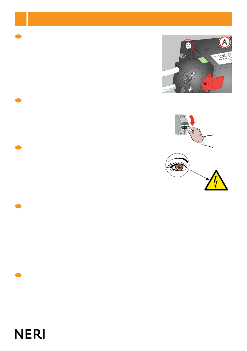
1°7° SOSTITUZIONE FUSIBILE - FUSE REPLACEMENTS - REPLACEMENT DU FUSIBLE -
AUSTAUSCH DER SICHERUNG - SUSTITUCIÓN DEL FUSIBLE
Alcune congurazioni di apparecchi sono munite di fusibile di protezione
collocato sulla piastra cablaggio (Fig. A). Attenzione, prima di effettuare
operazioni di verica o sostituzione del fusibile, disinserire
l’apparecchio dalla rete di alimentazione elettrica. Per sostituire il
fusibile, aprire l’apparecchio e sostituire il fusibile con uno di caratteristiche
uguali al precedente, come descritto sull’etichetta dell’apparecchio.
Vericare attentamente con esame a vista, se la causa della rottura del
fusibile è dovuta agli ausiliari elettrici che presentano anomalie visibili
(crepe, bruciature, parti annerite da fumi, morsetti allentati, ecc.). In questo
caso, prima di sostituire il fusibile, andrà vericato il funzionamento di tutti i
singoli componenti del cablaggio.
Some types of light xture are tted with a protection fuse located on the
wiring plate (Fig. A). Caution! Before any operations to check or replace
fuse, disconnect the light xture from the power supply. To replace
fuse, open xture and replace the fuse with one of an identical type (Fig.
B), as indicated on the product label. Carefully inspect visually to check
if blown fuse was caused by electrical components with visible defects
(cracks, burns, smoke marks, slack terminals, etc). In this case, check
correct operation of all electrical components before replacing fuse.
Certaines congurations d’appareils sont dotées d’un fusible de protection
placé sur la plaque de câblage (Fig. A). Attention, avant d’effectuer toute
opération de contrôle ou de remplacement du fusible, débrancher
l’appareil. Pour remplacer le fusible, ouvrir l’appareil et remplacer le fusible
par un autre présentant les mêmes caractéristiques que le précédent (Fig.
B), tel que précisé sur l’étiquette de l’appareil. Vérier visuellement avec le
plus grand soin si la rupture du fusible est due à des anomalies visibles des
auxiliaires électriques (ssures, brûlures, parties noircies par des fumées,
bornes desserrées, etc.). Dans ce cas, avant de remplacer le fusible,
vérier le fonctionnement de chaque composant du câblage.
Einige Apparatkongurationen können zum Schutz mit Sicherungen
auf der Verkabelungsplatte versehen sein (Abb. A). Achtung: vor
dem Durchführen von Überprüfungen oder dem Austauschen der
Sicherung muss man den Apparat von der Stromversorgung trennen.
Um die Sicherung auszutauschen, den Apparat öffnen und die Sicherung
durch eine andere mit den gleichen Eigenschaften (Abb. B), wie sie auf dem
Etikett desApparates beschrieben sind, ersetzen. Durch genaues Hinsehen
überprüfen, ob der Grund für die Zerstörung der Sicherung auf elektrisches
Zubehör zurückzuführen ist, das sichtbare Anomalien aufweist (Sprünge,
Brandecken, Rauch-geschwärzte Teile, gelockerte Klemmen usw.). In
diesem Fall muss das Funktionieren aller Verkabelungskomponenten
überprüft werden, bevor die Sicherung ausgetauscht wird.
Algunos tipos de aparatos incorporan un fusible protector situado en la
placa portacables (Fig. A). Atención: antes de efectuar operaciones de
comprobación o sustitución de los fusibles, desenchufen el aparato
de la red eléctrica. Para sustituir el fusible, abran el aparato y sustituyan
el fusible por uno de las mismas características del anterior (Fig. B), como
se describe en la etiqueta del aparato. Comprueben con un examen visual
si la causa de la rotura del fusible se debe a los auxiliares eléctricos que
presentan anomalías visibles (grietas, quemaduras, piezas ennegrecidas
por humo, bornes sueltos, etc...). Es tal caso, antes de sustituir el fusible,
habrá que comprobar el funcionamiento de cada pieza del cableado.
15
www. neri.biz
AB
19
I
GB
F
D
E
1°8°
OTTICHE - REFLECTOR - OPTIK - ELEMENTE - REFLECTORES
Gli apparecchi Light 104 sono congurati con due possibili sistemi ottici:
• ottica stradale mod. 1 (Fig. A).
• ottica ciclo pedonale mod. 9 (Fig. B).
The Light 104 light xtures can be congured with two different optics systems:
• Optic for street lighting mod. 1 (Fig. A).
• Optic for cycle-pedestrian lighting mod. 9 (Fig. B)
Les appareils Light 104 sont congurés avec deux systèmes optiques possibles :
• optique pour éclairage de rues mod. 1 (Fig. A).
• optique pour éclairage de parcours piétons-cyclistes mod. 9 (Fig. B).
Die Geräte Light 104 können mit zwei Optiksystemen konguriert werden:
• Optik für Straßenbeleuchtung mod.1 (Abb. A).
• Optik für Zyklus-Fußgängerbeleuchtung mod. 9 (Abb. B).
Las luminarias Light 104 se pueden congurar con dos sistemas ópticos:
• Optic para la iluminación de la calle mod. 1 (Fig. A).
• óptica para la iluminación de carril bici y peatonal mod. 9 (Fig. B).
16 17
L’installazione deve essere eseguita secondo le prescrizioni della norma CEI 64-8 Impianti elettrici di illuminazione pubblica
e similari. L’apparecchio è previsto solo per il funzionamento nella posizione per cui è stato progettato.
In fase di montaggio è cura dell’installatore vericare in particolare che l’accoppiamento braccio-apparecchio garantisca il
grado di protezione IP specicato sull’apparecchio stesso.
L’apparecchio deve essere utilizzato solo se completo degli schermi di protezione.
Se lo schermo risulta danneggiato o rotto, l’apparecchio non va utilizzato.
Ripristinare le condizioni originali prima di riutilizzarlo
Lo schermo di protezione è in vetro temperato.
Per i ricambi e la loro fornitura rivolgersi al costruttore dell’apparecchio.
Per l’alimentazione sono idonei cavi dotati di un isolamento supplementare o doppio.
Quando l’apparecchio è in classe II fare attenzione che, durante l’installazione, parti metalliche esposte non vadano in
contatto elettrico con parti dell’installazione elettrica collegate ad un conduttore di protezione.
L’apparecchio è idoneo per l’installazione all’interno e all’esterno.
Le lampade impiegate ad alogenuri metallici devono essere a bassa emissione UV.
Installation must be carried out in accordance with national standards. The xture is intended only to work in the position
for which it was designed. During assembly, the installer must make sure that the arm-xture coupling guarantees the IP
safety class specied on the xture.
The xture must be used only if complete with safety screens.
If the screen is damaged or broken, the xture must not be used.
Restore the original conditions before reusing.
The safety screens is in hardened glass.
For their spare parts and supplies, refer to the manufacturer of the equipment.
Cables with added or double insulation are recommended for the power supply.
If the lantern is installed under Class II protection standards, particular care must be taken while assembling to ensure that
exposed metal parts do not come into electrical contact with parts of the electrical installation connected to a protection
conductor. The light xture is suitable for internal and external installation.
If tted, halide vapour lamps must have low UV emission.
L’installation doit être effectuée selon les prescriptions nationales.
L’appareil est prévu uniquement pour le fonctionnement dans la position pour laquelle il a été conçu (voir dessins des
modèles dans les pages qui suivent). Lors du montage, l’installateur devra vérier surtout que l’accouplement bras-appareil
garantisse le degré de protection IP spécié sur l’appareil en question.
L’appareil pourra être utilisé uniquement s’il est pourvu des écrans de protection.
Si l’écran devait être endommagé ou cassé, l’appareil ne devra pas être utilisé.
Rétablir les conditions originales avant de l’utiliser à nouveau.
Le écran de sécurité est en verre trempé.
Pour les pièces de rechange et leur livraison, vous adresser au constructeur de l’appareil.
Les câbles d’alimentation appropriés doivent être dotés d’un guipage supplémentaire ou double. Lorsque l’appareil est en
classe II, s’assurer que, pendant l’installation, les parties métalliques exposées n’entrent pas en contact électrique avec
des parties de l’installation électrique reliées à un conducteur de protection.
L’appareil est approprié à une installation en intérieur et extérieurs.
Les lampes à vapeurs d’halogénures éventuellement employées doivent présenter une émission réduite d’ultraviolets.
9°
AVVERTENZE PER L’INSTALLAZIONE - INSTALLATION INFORMATION - PRECAUTIONS POUR
L’INSTALLATION - INSTALLATIONSANLEITUNG - ADVERTENCIAS PARA INSTALACIÓN
I
GB
F
17
www. neri.biz
9°
AVVERTENZE PER L’INSTALLAZIONE - INSTALLATION INFORMATION - PRECAUTIONS POUR
L’INSTALLATION - INSTALLATIONSANLEITUNG - ADVERTENCIAS PARA INSTALACIÓN
Die Installierung wird ausschließlich nach den Vorschriften der deutschen Normen durchgeführt. Der Apparat ist nur für den
Betrieb in der Position, für die er projektiert wurde, vorgesehen (siehe Modellzeichnungen auf den nachstehenden Seiten).
Bei der Installation liegt es in der Verantwortung des Installateurs, insbesondere sicherzustellen, dass die Kopplung Arm-
Apparat den auf dem Apparat selbst spezizierten IP Schutzgrad garantiert.
Der Apparat darf nur komplett mit Schutzschirmen benutzt werden.
Sollte der Schirm beschädigt oder zerstört sein, darf der Apparat nicht benutzt werden.
Stellen Sie den Originalzustand vor der erneuten Benutzung wieder her.
Schutzschirme sind Sekuritglas ausgestattet sein.
Nehmen Sie für Ersatzteile und deren Lieferung Kontakt mit dem Hersteller des Apparats auf.
Wenn der Apparat zur Klasse II gehört, muss man bei der Installation darauf achten, dass keine Metallteile mit Teilen der
Elektroinstallation Kontakt bekommen, die mit einem Schutzleiter verbunden sind.
Der Apparat ist für interne und externe Installation verwendbar.
Die evtl. verwendeten Halogenlampen dürfen nur eine geringe UV-Strahlung haben.
La instalación debe efectuarse según las prescripciones nacionales.
El aparato sólo puede funcionar en la posición para la cual ha sido proyectado (véanse los dibujos de los modelos en
las páginas siguientes). Durante el montaje, el instalador debe controlar atentamente que el acoplamiento brazo-aparato
garantice el grado de protección IP especicado en el aparato en cuestión.
El aparato sólo se puede utilizar con las pantallas de protección.
Si la pantalla se daña o se rompe, no utilicen el aparato.
Restablezcan las condiciones originales antes de volverlo a utilizar.
La pantalla de seguridad son de vidrio templado.
Para los recambios y su suministro, ponerse en contacto con el fabricante del aparato.
Para la alimentación son idóneos los cables dotados de aislamiento suplementario o doble.
Cuando el aparato está en clase II, presten atención a que durante la instalación las partes metálicas expuestas no entren
en contacto eléctrico con partes de la instalación eléctrica conectadas a un conductor de protección.
El aparato no es idóneo para la instalación interna y externa.
Las eventuales lámparas de vapor de haluro empleadas deben ser de emisión baja de rayos UV.
D
E
Label example - CE
230V-50Hz / IP66 (optic 1)
100W / MT-ST / E40
250V T6.3A
06/14 - lotto 00004
Made in Italy
Mod. Brevettato
SN104A211 3314
E
18 19
AExample of label - mark CE
230V-50Hz / IP66 (optic 1)
100W / MT-ST / E40
250V T6.3A
06/14 - lotto 00004
Made in Italy
Mod. Brevettato
SN104A211 3322
E
Lamps
(ILCOS CODE) Lampholder
MT-ST 70W E27
MT-ST 100W E40
MT (CPO-TW) 60W PGZ12
MT (CPO-TW) 90W PGZ12
PGZ12
Socket and lamps
E27 E40
SN104A
S = 0,053 m
2
Kg 4,5
22,5 cm
Ø 42 cm
G3/4”
I
GB
F
D
E
1°10° CARATTERISTICHE - CHARACTERISTICS - CARACTERISTIQUES -
EIGENSCHAFTEN - CARACTERISTÍCAS
Apparecchio per illuminazione stradale conforme alle norme CEI EN 60598-1:2001; 60598-2-3; Direttiva B.T. 2006/95/CE;
Direttiva EMC 2004/108/CE - 92/32/CEE - 98/68/CEE. Realizzato in lamiera d’alluminio. Attacco rapido in ottone lettato
maschio G3/4”, per ssaggio a sospensione. Piastra di cablaggio in lamiera di acciaio zincato. Alimentatore compatto
elettromagnetico o elettronico, portalampada in ceramica e schermo in vetro piano temprato trasparente o ghiacciato.
Ottiche in alluminio purissimo. Guarnizione in silicone. Verniciatura color grigio scuro tipo Neri.
Caratteristiche elettriche speciche, vedi etichetta dati posta sull’apparecchio (esempio Fig. A).
Street lighting xture in compliance with standards CEI EN 60598-1:2001; 60598-2-3; LV Directive 2006/95/EC; EMC
Directive 2004/108/EC - - 92/32/EEC - 98/68/EEC. Made from aluminium sheet metal, quick-t, male thread G3/4”
connector for suspended xing. Wiring plate in galvanized steel plate, with compact electromagnetic or electronic power
supply unit. Ceramic lamp holder. Flat tempered transparent or frosted glass screen.
Optics in pure aluminium. Silicone gaskets. Dark grey, Neri type paint.
For specic electrical characteristics, please see the data label afxed to the xture (Fig. A).
Appareil pour l’éclairage de rues, conforme aux normes CEI EN 60598-1:2001; 60598-2-3; Directive B.T. 2006/95/CE;
Directive EMC 2004/108/CE - 92/32/CEE - 98/68/CEE. Réalisé en tôle d’aluminium; raccord rapide en laiton leté mâle
G3/4” pour la xation suspendue. Plaque de câblage en tôle d’acier zingué. Alimentateur compact électromagnétique ou
électronique et douille en céramique; écrans en verre plat trempé transparent ou craquelé et joints en silicone.
Optique en aluminium très pur. Peinture gris foncé type Neri.
Caractéristiques électriques spéciques, voir l’étiquette des données positionnée sur l’équipement (exemple Fig. A).
Die Straßenleuchte entspricht den Anforderungen der Richtlinien CEI EN 60598-1:2001; 60598-2-3; Richtlinie B.T.
2006/95/CE; Richtlinie EMC 2004/108/CE - 92/32/CEE - 98/68/CEE. Aus Aluminiumblech mit Schnellkupplung mit
Messingaußengewinde G3/4”, zum Aufhängen. Verkabelungsplatte aus verzinktem Stahlblech; elektromagnetisches oder
elektronisches Kompaktnetzteil; Keramikfassung; Schirme aus transparentem oder gefrostetem, gehärtetem Flachglas;
nicht verstellbare, asymmetrische Optik aus reinem Aluminium; Silikondichtungen. Dunkelgraue Neri-Lackierung.
Spezische elektrische Eigenschaften siehe Typenschild auf dem Leuchtkörper (Beispiel Abb. A).
Aparato para alumbrado de carreteras conforme con las normas CEI EN 60598-1:2001; 60598-2-3; Directiva B.T. 2006/95/
CE; Directiva EMC 2004/108/CE - 92/32/CEE - 98/68/CEE. Realizado en chapa de aluminio, conexión rápida macho con
rosca G3/4” de latón para jación en suspensión. Placa de conexiones de chapa de acero galvanizado con alimentador
compacto electromagnético o electrónico y casquillo de cerámica. Difusores de cristal plano templado transparente o
efecto helado; óptica de aluminio superpuro y juntas de silicona. Pintura gris oscuro de tipo Neri.
Características eléctricas especícas, véase la etiqueta de datos de la luminaria (ejemplo Fig. A).
19
www. neri.biz
AB
I
GB
F
D
E
1°
11° ORIENTAMENTO OTTICA ASIMMETRICA - ASYMMETRICAL REFLECTOR POSITIONIN-
GORIENTATION DU RéFLECTEUR ASYMéTRIQUE - ASYMETRISCHER REFLEKTOR
AUSRIGHTUNGORIENTACIÓN DEL REFLECTOR ASIMéTRICO
Il corretto orientamento degli apparecchi con ottica, si ottiene posizionando l’apparecchio con l’ottica perpendicolare
alla carreggiata, con il portalampada dal lato del centro della carreggiata (vedi schema Fig. A).
The correct alignment for light xtures with reectors is obtained by positioning the xture with the reector perpendicular
to the roadway and the lamp-holder towards the centre of the road (see Fig. A).
Pour obtenir une orientation correcte des luminaires dotés de réecteur, placer le luminaire le réecteur perpendiculaire
à la chaussée, la douille devant ainsi se trouver du côté du centre de la chaussée (voir schéma Fig. A).
Die korrekte Ausrichtung der Apparate mit Optik erreicht man, indem man den Apparat mit zur Fahrbahn senkrechter
Optik installiert, mit der Lampenfassung an der Seite zur Fahrbahnmitte; folglich wird der Lampenkopf zum
Fußweg gerichtet sein (siehe Schema Abb. A).
La orientación correcta de los aparatos con pantalla protectora se obtiene colocando el aparato con la pantalla
perpendicular a la calzada, con el portalámpara hacia el lado central de la calzada (vean el dibujo Fig. A).
Attacco portalampada
Lamp-holder
Fixation de la douille
Lampenfassungsanschluss
Conexión portalámpara
Ottica
Reector
Réecteur
Optik
Reector
20 21
La garanzia del costruttore opera per anni 2 (due) dalla data di consegna. La garanzia è esclusa nelle ipotesi in cui sia fatto un
uso improprio dell’apparecchio, in caso di interventi o modiche non autorizzate dalla costruttrice, e comunque ogni qualvolta
non siano state rispettate le istruzioni del presente manuale. Qualsiasi intervento per modiche alle parti meccaniche ed
elettriche anche di lieve entità invalida ogni forma di garanzia e di responsabilità del costruttore.
The manfacturer’s guarantee is valid for 2 (two) years from the delivery date. The guarantee is invalidated if the light xture
is used improperly, in case of operations or modications that have not been authorized by the manufacturer, and in all other
situations in which the instructions given in this manual are not respected. Any kind of operation to modify mechanical or
electrical components, even if only slight, will invalidate all forms of guarantee and liability of the manufacturer.
La garantie du constructeur est valable 2 (deux) ans à partir de la date de la livraison. La garantie perd toute validité en cas
d’utilisation impropre de l’appareil, en cas d’interventions ou de modications non autorisées par le constructeur et, quoi qu’il
en soit, en cas de non-respect des instructions indiquées dans le présent manuel. Toute intervention de modication sur les
parties mécaniques et électriques, même légère, annule toute forme de garantie et de responsabilité du constructeur.
Die Herstellergarantie gilt für 2 Jahre (zwei) ab dem Lieferdatum. Die Garantie wird ausgeschlossen bei unsachgemäßer
Verwendung des Apparates, bei nicht vom Hersteller autorisierten Eingriffen oder Veränderungen und jedenfalls immer,
wenn die Anweisungen dieser Anleitung nicht beachtet worden sind. Jede auch geringfügige Änderungsmaßnahme an
mechanischen und elektrischen Teilen lässt jede Form von Garantie und Verantwortung des Herstellers ungültig werden.
La garantía del fabricante es válida durante 2 años (dos), a partir de la fecha de entrega. Queda excluida la garantía cuando
se realice un empleo inadecuado del aparato, en caso de intervenciones o modicaciones no autorizadas por el fabricante,
y en todo caso, cada vez que no hayan sido respetadas las instrucciones del presente manual. Cualquier intervención para
realizar modicaciones en las partes mecánicas y eléctricas, aunque sean de entidad leve, invalida cualquier forma de
garantía y exime de la responsabilidad al fabricante.
I
GB
F
D
E
1°
13° GARANZIA - GARANTEE - GARANTIE - GARANTIE - GARANTIA
I
GB
F
D
E
L’apparecchio è stato realizzato a regola d’arte. La sua durata ed efcienza sarà migliore se usato correttamente e con
interventi di manutenzione regolare. Questo apparecchio deve essere destinato solo all’uso per il quale è stato progettato, e
cioè l’illuminazione di ambienti esterni-interni. Ogni altro uso è considerato improprio e pericoloso, ed il costruttore non può
essere considerato responsabile per danni derivanti da un uso improprio e irragionevole.
The light xture has been manufactured in compliance with correct practice. Its duration and efciency will be greater if used
correctly and with regular maintenance operations. This light xture must be installed only for the use for which it was designed,
namely for the illumination of outdoor / indoor spaces - wet location. Any other use must be considered to be improper and
dangerous, and the manufacturer cannot be held liable for any damage caused by improper and unreasonable use.
L’appareil a été réalisé dans les règles de l’art. Sa durée et son efcacité seront meilleures s’il est utilisé correctement et soumis
à de régulières interventions d’entretien. Cet appareil ne doit être destiné qu’à l’utilisation pour laquelle il a été conçu, à savoir,
l’éclairage de milieux externe et interne. Toute autre utilisation étant considérée comme impropre et dangereuse, le constructeur
décline toute responsabilité en cas de dommages dérivant d’une utilisation impropre et irraisonnable de l’appareil.
Der Apparat ist fachgerecht hergestellt worden. Seine Lebensdauer und Efzienz wird besser sein, wenn er korrekt verwendet
und regelrecht gewartet wird. Dieser Apparat darf nur für den Zweck vorgesehen werden, für den er entwickelt wurde, das ist:
Beleuchten im externen und internen Bereich. Jede andere Verwendung ist als unsachgemäß und gefährlich anzusehen,
und der Hersteller kann nicht verantwortlich für Schäden gemacht werden, die aus einem unsachgemäßen und unvernünftigen
Gebrauch herrühren.
El aparato ha sido fabricado perfectamente. Su duración y eciencia resultarán mejores si se utiliza correctamente y se
realizan intervenciones regulares de mantenimiento. Este aparato debe ser destinado exclusivamente al uso para el cual
ha sido concebido, es decir: para alumbrar entornos interna y externa. Cualquier otro empleo se considera inadecuado y
peligroso, y el constructor no puede ser considerado responsable de ello.
1°12° DESTINAZIONE D’USO - INTENDED USE - UTILISATION DES LUMINAIRES
ZWECKBESTIMMUNG - UTILIZACIÓN

Other manuals for LIGHT 104

1

Other NERI Outdoor Light manuals

NERI LIGHT 801 Series User manual

NERI

NERI LIGHT 801 Series User manual

NERI LIGHT 700 User manual

NERI

NERI LIGHT 700 User manual

NERI Brenta bollards Operating and maintenance instructions

NERI

NERI Brenta bollards Operating and maintenance instructions

NERI LIGHT 100 User manual

NERI

NERI LIGHT 100 User manual

NERI LIGHT 21 Operating and maintenance instructions

NERI

NERI LIGHT 21 Operating and maintenance instructions

NERI LIGHT 103 Operating and maintenance instructions

NERI

NERI LIGHT 103 Operating and maintenance instructions

NERI Nashira 1191.050 User manual

NERI

NERI Nashira 1191.050 User manual

NERI Altair HERON Series User manual

NERI

NERI Altair HERON Series User manual

NERI Pictor Operating and maintenance instructions

NERI

NERI Pictor Operating and maintenance instructions

NERI 853 Series User manual

NERI

NERI 853 Series User manual

NERI LIGHT 600 User manual

NERI

NERI LIGHT 600 User manual

NERI CASTORE 1161.015 User manual

NERI

NERI CASTORE 1161.015 User manual

NERI Chara Series User manual

NERI

NERI Chara Series User manual

NERI LIGHT 104 User manual

NERI

NERI LIGHT 104 User manual

NERI Pictor Bollards Operating and maintenance instructions

NERI

NERI Pictor Bollards Operating and maintenance instructions

NERI Nebula BONEB Operating and maintenance instructions

NERI

NERI Nebula BONEB Operating and maintenance instructions

NERI Nebula Bollard Operating and maintenance instructions

NERI

NERI Nebula Bollard Operating and maintenance instructions

NERI Nebula S Operating and maintenance instructions

NERI

NERI Nebula S Operating and maintenance instructions

NERI LIGHT 804 User manual

NERI

NERI LIGHT 804 User manual

Popular Outdoor Light manuals by other brands

Luminaire led AOV13 Installation instruction sheet

Luminaire led

Luminaire led AOV13 Installation instruction sheet

bluesmart SN Series user manual

bluesmart

bluesmart SN Series user manual

MAD pier G46GT GLOBE quick start guide

MAD

MAD pier G46GT GLOBE quick start guide

Ashley Signature Design L207374 manual

Ashley

Ashley Signature Design L207374 manual

DekPro EFFEX installation guide

DekPro

DekPro EFFEX installation guide

Gama Sonic GS-104 instruction manual

Gama Sonic

Gama Sonic GS-104 instruction manual

Sulion KLEE 217011 manual

Sulion

Sulion KLEE 217011 manual

KSIX BXCQILAMP01 user manual

KSIX

KSIX BXCQILAMP01 user manual

OttLite 25D54BZX quick start guide

OttLite

OttLite 25D54BZX quick start guide

RUSTA HYBRID 108 CM manual

RUSTA

RUSTA HYBRID 108 CM manual

LIGMAN CAPSULE 1 installation manual

LIGMAN

LIGMAN CAPSULE 1 installation manual

EuroLite PAR-64 Profi Spot user manual

EuroLite

EuroLite PAR-64 Profi Spot user manual

Malatech AMETHYST 60 user manual

Malatech

Malatech AMETHYST 60 user manual

Silicon CPV Badr 1+G2 user manual

Silicon CPV

Silicon CPV Badr 1+G2 user manual

LF allen+roth PM21201-259 manual

LF

LF allen+roth PM21201-259 manual

Safavieh Lighting TBL4382 instructions

Safavieh Lighting

Safavieh Lighting TBL4382 instructions

Solight GL01 manual

Solight

Solight GL01 manual

mitzi LIZA HL321401 Assembly and mounting instructions

mitzi

mitzi LIZA HL321401 Assembly and mounting instructions

manuals.online logo
manuals.online logoBrands
  • About & Mission
  • Contact us
  • Privacy Policy
  • Terms and Conditions

Copyright 2025 Manuals.Online. All Rights Reserved.