manuals.online logo
Brands
  1. Home
  2. •
  3. Brands
  4. •
  5. NERI
  6. •
  7. Outdoor Light
  8. •
  9. NERI Chara Series User manual

NERI Chara Series User manual

Rev. A - 2011
Rev. A - 2013
I
GB
F
D
E
I
GB
F
D
E
CHARA
LIBRETTO ISTRUZIONI
PALI SERIE CHARA
INSTRUCTION BOOKLET
OF SERIES CHARA POSTS
NOTICE DE MONTAGE
DES SERIE CHARA
CANDELABRES
INSTALLATIONSANLEITUNG
FÜR MASTEN DER SERIE
CHARA
MANUAL DE
INSTRUCCIONES PARA
POSTES DE LA SERIE
CHARA
ATTENZIONE - CAUTION
ATTENTION - ACHTUNG
ATENCIÓN
Questo manuale va letto
e conservato con molta attenzione
This manual should be read with
attention and kept with great care
Ce manuel doit être lu
très attentivement et soigneusement
conservé
Die Anleitung sollte mit großer
Aufmerksamkeit gelesen und
aufbewahrt werden
Leer este manual con atención y con-
servarlo en un buen estado.
NERI S.p.A.
S.S. EMILIA 1622 - 47020 LONGIANO (FC) - ITALY
Tel. +39 0547 652111 Fax +39 0547 54074
www.neri.biz - [email protected]
Certicato/Certicate
9105.DONE
ISO 9001:2008
Certicato/Certicate
9191.NER1
ISO 14001:2001
2
3
Ogni riproduzione ed utilizzo per ni propri di questo manuale non è consentita. Tutti i diritti sono riservati.
E’ vietata la riproduzione anche parziale di esso senza il consenso scritto della Neri spa.
La Neri spa si riserva il diritto di apportare modiche ai propri prodotti e alla documentazione senza obbligo di preavviso.
Any reproduction and use for its own purposes of this manual is not permitted. All rights reserved.
Reproduction of this manual, even partially, is forbidden without written consent from Neri spa.
Neri spa reserves the right to modify its products and documentation without obligation to give prior warning.
Toute reproduction et utilisation pour ses propres ns de ce manuel n’est pas autorisée. Tous droits réservés.
Ce manuel ne peut être reproduit, même partiellement, sans l’accord écrit de Neri spa.
Neri spa se réserve le droit d’apporter toutes modications à ses produits et à la documentation sans préavis.
Eine Vervielfältigung und Nutzung für den eigenen Zweck dieses Handbuches ist nicht gestattet.Alle Rechte vorbehalten.
Seine - auch auszugsweise - Reproduktion ohne schriftliche Zustimmung der Neri spa ist verboten.
Die Neri spa behält sich das Recht vor, an ihren Produkten und der Dokumentation Veränderungen vorzunehmen,
ohne dies vorher ankündigen zu müssen.
Cualquier reproducción y uso para sus propios nes de este manual no está permitido. Todos los derechos reservados.
Se prohíbe su reproducción incluso parcial sin autorización por escrito de la empresa Neri spa.
Neri spa se reserva el derecho de aportar cambios a sus productos y a la documentación sin obligación de aviso previo.
Autori: Isacco Neri - Titolo: Libretto Istruzioni Pali “Chara” - Pubblicatore: Neri spa
Progetto e coordinamento graco: Daniele Lombardi - Stampa: Grache MDM srl, Forlì FC, Giugno 2013.
Tutti i diritti riservati. E’ fatto espresso divieto a qualunque riproduzione parziale o totale del presente testo.
DESIGN PATENTED, PRINTED IN ITALY
2
3
www. neri.biz
I
I
I
I
I
I
I
I
I
I
I
I
G B
G B
G B
G B
G B
G B
G B
G B
G B
G B
G B
G B
F
F
F
F
F
F
F
F
F
F
F
F
D
D
D
D
D
D
D
D
D
D
D
D
E
E
E
E
E
E
E
E
E
E
E
E
I
I
G B
G B
F
F
D
D
E
E
I
I
I
G B
G B
G B
F
F
F
D
D
D
E
E
E
SIMBOLI ED ETICHETTA
SYMBOLS AND LABEL
SYMBOLES ET ETIQUETTE
SYMBOLE UND AUFKLEBER
SÍMBOLOS Y ETIQUETAS
1°
pag 4
NOTE GENERALI ALLA CONSEGNA
GENERAL NOTES ON DELIVERY
CONSIGNES GÉNÉRALES À LA LIVRAISON
ALLGEMEINE HINWEISE BEI DER LIEFERUNG
NOTAS GENERALES DE ENTREGA
2°
pag 5
PRESCRIZIONI DI SICUREZZA
SAFETY PRECAUTIONS
PRESCRIPTIONS DE SECURITE
SICHERHEITSVORSCHRIFTEN
NORMAS DE SEGURIDAD
3°
pag 6
DISIMBALLAGGIO ANIME PALI
POST CORES UNPACKING
DÉBALLAGE AMES DE CANDELABRES
AUSPACKEN MASTKERNE
DESEMBALAJE DE LAS ALMAS DE LOS POSTES
4°
pag 7
SISTEMA DI FISSAGGIO - MURATURA
FIXING SYSTEM - CEMENTING IN
SYSTEME D’ANCRAGE - SCELLEMENT DIRECT
BEFESTIGUNGSSYSTEM – EINMAUERN
SISTEMA DE FIJACIÓN-MURAL
5°
pag 8
SISTEMA DI FISSAGGIO - FLANGIA
FIXING SYSTEM - FLANGE
SYSTEME D’ANCRAGE - SEMELLE DE FIXATION
BEFESTIGUNGSSYSTEM – FLANSCH
SISTEMAS DE FIJACIÓN-BRIDA
6°
pag 9
APPLICAZIONE GUAINA PROTETTIVA
FITTING OF PROTECTIVE SHEATH
APPLICATION DE LA GAINE DE PROTECTION
AUFBRINGUNG DES SCHUTZMANTELS
APLICACIÓN DE UNA FUNDA PROTECTORA
7°
pag 10-11
PLINTO DI FONDAZIONE
CROSS SECTION
MASSIF D’ANCRAGE
FUNDAMENTSOCKEL
PLINTO DE CIMENTACIÓN
8°
pag 12
IMBRACATURA PALO
POST SLINGING
ÉLINGAGE CANDÉLABRE
ANSCHLAG LICHTMAST
ESLINGADO DEL POSTE
9°
pag 13
MESSAATERRRA
GROUND CONNECTION
MISE A LA TERRE
ERDUNG
COLOCACIÓN EN TIERRA
11°
pag 17
PROTEZIONI FINALI
FINAL PROTECTION
PROTECTIONS FINALES
SCHUTZBEHANDLUNG
PROTECCIÓN FINAL
12°
pag 18
DISIMBALLO
UNPACKING
DEBALLAGE
AUSPACKEN
DESEMBALAJE
13°
pag 20
INSTALLAZIONE
INSTALLATION
INSTALLATION
INSTALLATION
INSTALACIÓN
14°
pag 21-22
ASSEMBLAGGIO E IMBRACATURA
ASSEMBLY AND LIFTING HARNESS
ASSEMBLAGE ET ÉLINGAGE
ZUSAMMENBAU UND MONTAGEGESCIRR
ENSAMBLAJE Y EMBRAGADO
15°
pag 24-25
INSTALLAZIONE ANIME PALI
POST CORES INSTALLATION
INSTALLATION AMES CANDELABRES
INSTALLATION MASTKERNE
INSTALACIÓN DE LAS ALMAS EN LOS POSTES
10°
pag 14-16
INSTALLAZIONE
INSTALLATION
INSTALLATION
INSTALLATION
INSTALACIÓN
16°
pag 26-27
PROTEZIONI FINALI
FINAL PROTECTION
PROTECTIONS TERMINALES
ABSCHLUSSKAPPEN
PROTECCIONES FINALES
17°
pag 28
INTRODUZIONE - INTRODUCTION - INTRODUCTION
EINLEITUNG - INTRODUCCIÓN PALI - POSTS - CANDELABRES - MASTEN
POSTES
CIME - TOP SECTIONS - BOUQUETS - MASTSPITZEN
POSTES
INDICE - CONTENTS - INDEX - INHALTVERZEICHNIS - INDICE
CODICE - CODE
9525.322.010
DESCRIZIONE - DESCRIPTION
BASAMENTO
BASE
I
G B
F
D
E
4
5
1°
I
I
G B
G B
F
F
D
D
E
E
I simboli mostrati sopra hanno il seguente signicato:
Fig. 1 > ABBIGLIAMENTO DA LAVORO - Fig. 2 > SCARPE ANTINFORTUNISTICHE - Fig. 3 > CASCO OBBLIGATORIO - Fig. 4 > GUANTI
DA LAVORO, Fig. 5 > PERICOLO PER L’OPERATORE, Fig. 6 > DANNI AI COMPONENTI, Fig. 7 > INQUINAMENTO AMBIENTALE,
Fig. 8 > NOTA INFORMATIVA, Fig. 9 > VERIFICATECNICA.
The symbols shown above have the following meanings:
Fig. 1 > WORK APPAREL - Fig. 2 > SAFETY SHOES - Fig. 3 > OBLIGATORY HELMET - Fig. 4 > WORK GLOVES, Fig. 5 > DANGER FOR
THE OPERATOR, Fig. 6 > DAMAGE TO COMPONENTS, Fig. 7 > ENVIRONMENTAL POLLUTION, Fig. 8 > INFORMATIVE NOTE, Fig. 9 >
TECHNICAL CHECK.
Les symboles indiqués ci-dessus correspondent aux signications suivantes:
Fig. 1 > VÊTEMENTS DE TRAVAIL - Fig. 2 > CHAUSSURES DE SÉCURITÉ - Fig. 3 > CASQUE OBLIGATOIRE - Fig. 4 > GANTS DE TRAVAIL,
Fig. 5 > DANGER POUR L’OPÉRATEUR, Fig. 6 > DOMMAGES AUX COMPOSANTS, Fig. 7 > POLLUTION DE L’ENVIRONNEMENT, Fig. 8 >
NOTE D’INFORMATION, Fig. 9 > VÉRIFICATION TECHNIQUE.
Die oben gezeigten Symbole haben folgende Bedeutung:
Abb. 1 > ARBEITSKLEIDUNG - Abb. 2 > SCHUTZSCHUHE - Abb. 3 > HELMPFLICHT - Abb. 4 > ARBEITSHANDSCHUHE, Abb. 5 >
GEFAHR FÜR DEN TECHNIKER, Abb. 6 > SCHÄDEN AN DEN KOMPONENTEN, Abb. 7 > UMWELTVERSCHMUTZUNG, Abb. 8 >
INFORMATIONSBLATT, Abb. 9 > TECHNISCHE KONTROLLE.
Los símbolos mostrados arriba tienen el siguiente signicado:
Fig. 1 > ROPA DE TRABAJO OBLIGATORIA - Fig. 2 > CALZADO DE SEGURIDAD OBLIGATORIO - Fig. 3 > CASCO DE SEGURIDAD
OBLIGATORIO - Fig. 4 > GUANTES DE SEGURIDAD OBLIGATORIOS, Fig. 5 > PELIGRO PARA EL OPERADOR, Fig. 6 > DAÑOS A LOS
COMPONENTES, Fig. 7 > CONTAMINACIÓN DEL MEDIO AMBIENTE, Fig. 8 > NOTA INFORMATIVA, Fig. 9 > COMPROBACIÓN TÉCNICA.
La Neri spa è impegnata costantemente nella ricerca e progettazione di prodotti di alta qualità, lunga durata e sicurezza. Questo manuale
intende presentare le metodiche di installazione corrette dei pali, ponendosi come guida nei confronti di installatori professionali. A tale scopo
questo manuale va letto con molta attenzione.
Neri spa is constantly committed to research and design for products of high quality, durability and safety. This manual aims to present correct
installation procedures for posts as a guide for professional installers. To this end the manual should be read with extreme attention.
Neri spa a toujours eu pour objectif la recherche et la conception de produits de haute qualité, offrant longévité et sécurité. Ce manuel, qui
présente les modes d’installation corrects des candélabres, est un guide à l’adresse des installateurs professionnels. Il doit donc être lu très
attentivement.
Die Neri spa ist konstant um Forschung und Entwicklung zeitbeständiger und sicherer Produkte von hoher Qualität bemüht. Dieses Handbuch
stellt die korrekten Installationsmethoden für pfähle und bietet sich gegenüber professionellen Installateuren als ein Ratgeber an. Deswegen
sollte dies Handbuch sehr aufmerksam gelesen werden.
La empresa Neri spa trabaja de continuo en el estudio y proyección de productos de alta calidad, larga duración y seguridad. Este manual pre-
sentará los métodos de instalación correcta de postes, siendo una guía para instaladores profesionales. Por ello, este manual debe leerse con
gran detenimiento.
Ogni elemento è contrassegnato da una etichetta adesiva posta sull’imballo. Vi sono riportati il codice e la descrizione, due dati basilari con cui
è possibile identicarlo.
Every element of the bollards is marked with a sticker on the packing. This shows the code and the description, the two essential items of
information for identication.
Tous les éléments bornes de dissuasion portent une étiquette adhésive placée sur l’emballage. Sur cette étiquette gurent le code et la
description, deux données fondamentales pour leur identication.
Jedes Poller ist durch einen Aufkleber auf der Verpackung gekennzeichnet. Darauf benden sich der Code und die Beschreibung, zwei
Basisdaten, durch die man es identizieren kann.
Cada elemento para bolardos está marcado con una etiqueta adhesiva colocada sobre el embalaje. Aparecen allí el código y la descripción,
dos datos básicos con que se pueden identicar.
INTRODUZIONE - INTRODUCTION - INTRODUCTION - EINLEITUNG - INTRODUCCIÓN
SIMBOLI ED ETICHETTA - SYMBOLS AND LABEL- SYMBOLES ET ETIQUETTE
SYMBOLE UND AUFKLEBER - SÍMBOLOS Y ETIQUETAS
Fig. 1 Fig. 2 Fig. 3 Fig. 4 Fig. 5 Fig. 6 Fig. 7 Fig. 8 Fig. 9
3°
A C
B
4
5
www. neri.biz
2°
I
G B
F
D
E
Gli elementi dei pali possono esere spediti e consegnati in vari modi:
A) elementi singoli sfusi; B) elementi raggruppati su bancale in legno; C) elementi raggruppati in casse di legno su bancale.
L’imballo dei singoli elementi può essere realizzato con cartone in vari strati, scatole di cartone, sacchetti di nylon.
In ogni caso comunque al ricevimento della merce controllare che:
1) l’imballo sia integro; 2) la fornitura corrisponda all’ordine (vedi bolla di consegna); 3) non vi siano parti mancanti.
In caso di danni o parti mancanti, informare immediatamente e in modo dettagliato (e/o con foto) la Neri spa.
The elements of the posts can be shipped and delivered in various ways:
A) loose single elements; B) elements packed together on wooden pallet; C) elements packed together in wooden crates on pallet.
The single elements can be packed with several layers of cardboard, cardboard boxes and plastic bags.
On receipt of the goods, always:
1) check that packing is undamaged; 2) check that goods received correspond to order (consult delivery note); 3) check that there are no missing
parts.
In case of damage or missing parts, immediately inform Neri spa, giving full details (and/or with photograph).
Les éléments des candélabres peuvent être expédiés et livrés de différentes façons:
A) éléments seuls en vrac; B) éléments groupés sur palette en bois; C) éléments groupés dans des caisses en bois sur palette.
L’emballage de chaque élément peut être réalisé dans des feuilles de carton, des boîtes en carton, des sacs en nylon.
Dans tous les cas, s’assurer dès la réception de la marchandise que:
1) l’emballage soit intact; 2) la fourniture corresponde à la commande (voir bulletin de livraison); 3) il ne manque aucune partie.
En cas de dommages ou de parties manquantes, en informer immédiatement d’une manière détaillée (et/ou avec photo) Neri spa.
Die Gusseisenelemente der Pfähle können auf verschiedene Weise transportiert und angeliefert werden:
A) einzelne Elemente; B) gruppierte Elemente auf Palette; C) gruppierte Elemente in Holzkisten auf Palette. Die Verpackung der einzelnen Ele-
mente kann aus Karton in mehreren Lagen bestehen, aus Kartonschachteln, aus Nylonsäcken. Jedenfalls muss man beim Wareneingang stets
kontrollieren, dass:
1) die Verpackung unversehrt ist; 2) die Lieferung der Bestellung entspricht (siehe Lieferschein); 3) keine Teile fehlen.
Bei Schäden oder fehlenden Teilen sofort und detailliert (u./o. mit Foto) die Neri spa informieren.
Los elementos de los postes se pueden expedir y entregar de varias formas:
A) elementos individuales sueltos; B) elementos agrupados en palets de madera; C) elementos agrupados en cajas de madera sobre palets.
El embalaje de cada elemento individualmente se puede realizar con cartones de varios estratos, cajas de cartón, sacos de nilón.
De todos modos al recibir la mercancía se deberá controlar:
1) que el embalaje esté íntegro; 2) que el suministro corresponda al pedido (ver albarán); 3) que no falten piezas.
En caso de daños o piezas que falten, informar a Neri spa de inmediato y con detalles (y/o con foto).
NOTE GENERALI ALLA CONSEGNA - DELIVERY INFORMATION - NOTES GENERALES POUR LA LIVRAISON
ALLGEMEINE ANMERKUNGEN ZUR ANLIEFERUNG - NOTAS GENERALES A LA ENTREGA
6
7
3°
I
G B
F
D
E
In base alle varie direttive in vigore nei vari paesi europei ed extraeuropei, nel luogo di lavoro devono essere rispettate determinate regole.
Le indicazioni di sicurezza non hanno lo scopo di alterare o modicare le direttive sopra menzionate; il loro unico scopo è quello di sottolinearle o amplicarle. Queste
prescrizioni di sicurezza sono indirizzate agli installatori professionali, i quali devono attentamente leggere e comprendere questo manuale di installazione.
ATTENZIONE, la non osservanza delle prescrizioni citate in questo manuale aumenta il rischio di incidenti.
Prima di effetuare qualsiasi operazione munirsi di: casco antiurto, guanti da lavoro, scarpe antifortunistiche, abbigliamento da lavoro ed eventualmente in base al
peso dell’elemento da sollevare (consultare tabella pesi e codici) di un mezzo di sollevamento meccanico (gru, carrello, ecc.).
A variety of rules must be followed in workplaces, depending on the legislation applicable in different countries of Europe and elsewhere.
The aim of the safety precautions illustrated here is not to replace or modify this applicable legislation, but solely to emphasize or reinforce it. These safety
precautions are intended for professional installers, who must carefully read and understand this installation manual.
WARNING, failure to observe the prescriptions given in this manual will increase the risk of accidents.
Before carrying out any operations whatsoever installers must put on: safety helmets, work gloves, safety footwear and suitable working clothes. Depending on
the weight of the element to be lifted (consult chart of weights and codes), mechanical lifting equipment (crane, forklift, etc) must be provided.
Conformément aux différentes directives en vigueur dans les pays européens et extra-européens, les lieux de travail sont soumis à des règles précises qui
doivent être respectées. Ces indications de sécurité n’entendent ni modier ni altérer les directives susdites mais ont pour but de les souligner ou d’en étendre
l’application. Ces prescriptions de sécurité s’adressent aux installateurs professionnels, qui devront lire attentivement ce manuel d’installation et en
comprendre parfaitement le contenu.
ATTENTION - La non-observation des prescriptions indiquées dans ce manuel augmente le risque d’accidents.
Avant d’effectuer toute opération, s’équiper de: casque antichoc, gants de travail, chaussures de sécurité, habillement de travail et, éventuellement, en fonction
du poids de l’élément à soulever (consulter le tableau des poids et codes) d’un appareil de levage mécanique (grue, chariot, etc.).
AufGrundlagederverschiedenenineuropäischenundaußereuropäischenLänderngeltendenVorschriften,müssenamOrtderArbeitbestimmteRegelneingehalten
werden. Die Sicherheitsangaben haben nicht den Sinn, die o.a. Vorschriften zu verändern; ihr einziger Zweck ist es, sie zu unterstreichen oder zu erweitern.
Diese Sicherheitsvorschriften wenden sich an professionelle Installateure, die dieses Installationshandbuch aufmerksam lesen und begreifen müssen.
ACHTUNG, Wenn die in diesem Handbuch angegebenen Vorschriften nicht eingehalten werden, erhöht sich die Unfallgefahr.
Vor der Durchführung vonArbeiten muss man sich eindecken mit: Schutzhelm,Arbeitshandschuhen, unfallsicheren Schuhen,Arbeitsbekleidung und evtl. aufgrund
des Gewichtes des anzuhebenden Elements (nachsehen in der Tabelle der Gewichte und Codes) mit einem mechanischen Hebewerkzeug (Kran, Hubwagen usw.).
DeacuerdoconlasdiversasdirectivasenvigorenlospaíseseuropeosyenlosdefueradeEuropa,enellugardetrabajosedebenrespetardeterminadasnormas.Las
normas de seguridad no tienen el objetivo de alterar o modicar las directivas mencionadas anteriormente; el único objetivo es el de ponerlas en evidencia o ampliarlas. Estas
normasdeseguridadsedirigenalosinstaladoresprofesionales,loscualesdebenleeratentamenteycomprender perfectamenteestemanualdeinstalación.
ATENCIÓN: el incumplimiento de las normas contenidas en este manual hace aumentar el riesgo de accidente.
Antes de iniciar cualquier trabajo, equiparse con: casco de seguridad, guantes de trabajo, calzado especial de trabajo, ropa de trabajo y, dependiendo del peso
que se deba elevar (consultar la tabla de pesos y códigos), un medio de elevación mecánica (grúa, carretilla etc.).
TABELLA CODICI ANIME PALI - CODE CHART FOR POST CORES - TABLEAU DES CODES DES AMES DE CANDELABRE
TABELLE DER CODES DER KERNMASTEN - TABLA DE CÓDIGOS DE ALMAS PARA POSTES
Peso e altezza massimi per tipo di anima - Maximum weight and height for core types - Poids et hauteur maximaux par type d’âme
Gewicht und maximale Höhe je Seelentyp - Peso y altura máximos por tipo de alma
PRESCRIZIONI DI SICUREZZA - SAFETY PRECAUTIONS
PRESCRIPTIONS DE SECURITE - SICHERHEITSVORSCHRIFTEN - NORMAS DE SEGURIDAD
ATTENZIONE - CAUTION
ATTENTION - ACHTUNG
ATENCIÓN
8300.500....
8300.501....
8300.600....
8300.601....
8300.700....
8300.701....
623
623
723
723
823
823
PALO
POST
CANDELABRE
MUST
POSTE
Kg h. cm.
68
65
76
70
100
94
C E
D
A B
6
7
www. neri.biz
4°
I
G B
F
D
E
Per il disimballo dei fasci di anime (in base al tipo di imballo omettere ciò che non serve) comportarsi nel seguente modo: 1) recintare la zona di lavoro; 2) dotarsi
di una robusta corda (D) da legare in prossimità della parte terminale del fascio (Fig. A); 3) predisporre a terra una robusta stuoia per la protezione delle parti
verniciate; 4) mettersi dietro la parte terminale del fascio e tagliare la centina (Fig. B) (ATTENZIONE - tale manovra può provocare il rotolamento di alcune
anime del fascio verso terra); 5) lentamente sciogliere la corda (D) messa a protezione.
IMPORTANTE - non trascinare o rotolare le anime a terra, si possono danneggiare.
ATTENZIONE - La non osservanza delle prescrizioni citate sopra aumenta il rischio di incidenti.
IMPORTANTE - Non disperdere l’imballo nell’ambiente, potrebbe essere fonte di pericolo e inquinamento. Seguire le normali procedure di
smaltimento dei riuti urbani (Fig. C) in conformità alle norme vigenti.
IMPORTANTE - L’anima è protetta da un’apposita pellicola antigrafo (Fig. E), che non dovrà essere rimossa durante il disimballo ma solamente dopo
l’installazione delle basi.
To unpack, proceed as follows (disregard instructions that do not apply to type of packing received): 1) Fence off the work area. 2) Tie a strong rope (F) round one
end of the bundle of cores (Fig. A). 3) Lay a robust mat on ground to protect paintwork (Fig. A). 4) Stand behind the end of the bundle and cut strapping (Fig. B)
(CAUTION: some cores of the bundle may roll onto the ground as a result of this operation). 5) carefully until the rope (D) tted for protective purposes.
IMPORTANT – do not drag or roll the cores on the ground as this may result in damage.
CAUTION – Failure to apply the precautions illustrated in this manual will increase the risk of accidents.
IMPORTANT – Do not dispose incorrectly of packaging materials, which could be a source of pollution and danger. Follow normal waste disposal
procedures for urban wastes (Fig. C) in compliance with applicable legislation.
IMPORTANT - The core is protected by a special scratch-proof lm (Fig. E)which mustnotberemovedduring unpacking but only after thebaseshavebeeninstalled.
Pour le déballage des âmes en faisceaux (en fonction du type d’emballage, omettre les précisations inutiles) il est conseillé de suivre les indications suivantes:
1) délimiter la zone de travail ; 2) se munir d’une corde robuste (D) à nouer à proximité de la partie terminale du faisceau (Fig. A) ; 3) étendre sur le sol une
robuste natte an de protéger les parties peintes ; 4) se placer derrière la partie terminale du faisceau et couper la bande de cerclage (Fig. B) (ATTENTION –
cette manoeuvre peut provoquer le roulement au sol de certaines âmes) ; 5) dénouer lentement la corde de protection (D).
IMPORTANT - Ne pas traîner ou faire rouler les âmes sur le sol an d’éviter tout dommage.
ATTENTION - La non-observation des prescriptions citées ci-dessus augmente le risque d’accidents.
IMPORTANT - Ne pas disperser l’emballage dans l’environnement, car il pourrait être source de danger ou pollution. Suivre les normales
procédures d’élimination des déchets urbains (Fig. C) conformément aux normes en vigueur.
IMPORTANT - L’âme est protégée par une pellicule anti-rayures (Fig. E) prévue à cet usage, qui ne devra pas être retirée pendant le déballage, mais
uniquement après l’installation des bases.
Beim Auspacken der Elemente (auf Basis des Verpackungstyps das weglassen, was nicht dienlich ist) muss man wie folgt vorgehen: 1) den Arbeitsbereich
absperren; 2) ein robustes Tau besorgen (F), das man nahe am Ende um das Bündel bindet; 3) auf dem Boden eine robuste Matte zum Schutz der lackierten
Teile ausbreiten (
Abb
. A); 4) sich hinter das Bündelende stellen und das Halteband durchtrennen (
Abb.
B) (ACHTUNG, es besteht Quetschgefahr); 5)
langsam das Schutzseil lösen (D).
WICHTIG - weder die Mastkerne am Boden ziehen noch rollen, damit sie nicht beschädigt werden.
ACHTUNG - Die Nichtbeachtung dieser Anweisungen erhöht das Unfallrisiko.
WICHTIG - Die Verpackung nicht in der Umgebung liegen lassen, sie könnte eine Gefahrenquelle sein und die Umwelt verschmutzen. Folgen Sie
den normalen Verfahren zur Beseitigung von städtischenAbfällen (
Abb.
C) entsprechend den geltenden Vorschriften.
WICHTIG - Das Mastrohr ist durch eine Kratzschutzfolie geschützt (Abb. E). Diese Folie darf beim Entfernen der Verpackung nicht entfernt werden, sondern
erst nach der Montage der Unterteile.
Para desembalar los haces de almas (según el tipo de embalaje omitir lo que no sirve) y realizar las siguientes operaciones: 1) Delimitar la zona de trabajo; 2)
Utilizar una maroma robusta (F) para ligar en la parte terminal del haz (Fig. A); 3) Poner en el suelo una estera gruesa para proteger las piezas pintadas; 4)
Ponerse detrás de la parte nal del haz y cortar la tira envolvente (Fig. B) (ATENCIÓN: dicha maniobra puede provocar el rodamiento por tierra de algunas
almas que escapen del haz); 5) desatar la cuerda (D) de protección lentamente.
IMPORTANTE – no arrastrar ni girar las almas mientras están en el suelo, podrían dañarse.
ATENCIÓN- El no observar las normas de seguridad citadas anteriormente implica aumentar el riesgo de accidentes.
IMPORTANTE- No dejen el embalaje tirado por ahí, podría resultar fuente de peligro o de contaminación. Sigan el procedimiento normal de retirada
de la basura urbana (Fig. C) según las leyes vigentes.
IMPORTANTE- El alma está protegida por una película antirrayado (Fig. E), que sólo se debe eliminar después de haber instalado las bases y no tras el desembalaje.
ATTENZIONE PERICOLO
CAUTION : DANGER
ATTENTION DANGER
ACHTUNG GEFAHR
ATENCIÓN, PELIGRO
IMPORTANTE
IMPORTANT
IMPORTANT
WICHTIG
IMPORTANTE
DISIMBALLAGGIO ANIME PALI - POST CORES UNPACKING - DÉBALLAGE ÂMES CANDÉLABRES -
AUSPACKEN MASTKERNE - DESEMBALAJE DE LAS ALMAS DE LOS POSTES
A
A2
35
h
Ø
A1
TABELLE INFORMATIVE
INFORMATION CHART
TABLEAUX INFORMATIFS
INFORMATIONSTABELLEN
TABLA INFORMATIVA
PALO - POST- CANDELABRE
PFAHL - POSTES
Ø cm h. cm
PALI SERIE CHARA
CHARA SERIES POSTS
CANDÉLABRES SÉRIE CHARA
MASTEN SERIE CHARA
POSTES DE LA SERIE CHARA
8300.500....
8300.600....
8300.700....
14,0
14,0
14,0
70
70
70
B
Quota zero
Zero position
Cote zéro
Höhe Null
Cota cero
8
9
5°
I
G B
F
D
E
IMPORTANTE - Dati per la messa in opera delle anime con muratura.
Lo schema illustrato in Fig. A, mostra un esempio tipico di anima con muratura. Tutte le anime con muratura sono dotate di: un tondino di riferimento di quota
zero; un bullone per la messa a terra; un’asola (A1) per l’entrata cavi elettrici, e di una seconda asola (A2) per l’installazione di una morsettiera.
Per le misure dei diametri (Ø) e altezza (h) delle murature consultare la tabella informativa Fig. B.
IMPORTANT - Data for installation of cement-in cores.
Fig. A shows a typical example of installation by cementing in. All cores to be installed in this way are complete with: a reference mark to show zero position; an
earthing bolt; a slot (A1) for entrance of electrical cables, and a second slot (A2) for installation of a terminal board.
For diameters (Ø) and depths (h) of installation by cementing in consult the information chart in Fig. B.
IMPORTANT – Données pour l’installation des âmes par scellement direct.
Le schéma illustré sur la Fig. A présente un typique exemple d’âme à sceller directement dans le sol. Toutes ces âmes sont dotées de:
une encoche de repère de “cote zéro”; un boulon pour la mise à la terre; une boutonnière (A1) pour l’entrée des câbles électriques, et une seconde
boutonnière (A2) pour l’installation d’un coffret de connexion.
Pour les dimensions des diamètres (Ø) et hauteurs (h) des extrémités de scellement, consulter les tableaux informatifs Fig. B.
WICHTIG - Angaben über die Installation der Mastkerne mit Einmauerung.
Das in
Abb
. Aillustrierte Schema zeigt ein typisches Beispiel für eine Seele mit Einmauerung. Alle einzumauernden Seelen sind ausgestattet mit: einem
Rundeisen als Bezugspunkt für die Höhe Null; einer Mutterschraube für die Erdung; einer Öffnung (A1) für den Einlass von Stromkabeln und einer zweiten (A2)
für die Installation eines Klemmbretts.
Für die Maße der Durchmesser (Ø) und der Höhe (h) der Einmauerung die Informationstabellen
Abb.
Bzu Rate ziehen.
IMPORTANTE – Datos para la puesta en obra de las almas con mampostería.
El esquema ilustrado en la Fig. A muestra un ejemplo típico de alma con mampostería. Todas las almas con mampostería están dotadas de: un redondelito de
referencia de cota cero; un perno para la colocación en tierra; un ojal (A1) para la entrada de los cables eléctricos, y un segundo ojal (A2) para la instalación
de un tablero de bornes.
Para las normas del diámetro (Ø) y la altura (h) de la mampostería consultar la tabla informativa Fig. B.
SISTEMA DI FISSAGGIO CON MURATURA • FIXING SYSTEM – CEMENTING IN
SYSTEME D’ANCRAGE PAR SCELLEMENT DIRECT • BEFESTIGUNGSSYSTEM MIT EINMAUERN
SISTEMA DE FIJACIÓN CON MAMPOSTERÍA
8300.501....
8300.601....
8300.701....
F2
F2
F2
2,2
60°
ø 26,6
ø 9
ø 20
F2
C
A1
Ø
PALO - FLANGIA
POST - FLANGE
CANDELABRE-SEMELLE
PFAHL - FLANSCH
POSTES - BRIDA
Quota zero
Zero position
Cote zéro
Höhe Null
Cota cero
8
9
www. neri.biz
6°
I
G B
F
D
E
IMPORTANTE - Dati per la messa in opera delle anime con angia.
Lo schema illustrato in Fig. C, mostra un esempio tipico di anima con angia. Tutte le anime con angia sono dotate di: un bullone per la messa a terra; un’asola
(A1) per l’installazione di una morsettiera; sei asole Ø 2,2 cm per tirafondi; un foro centrale Ø 9 cm per il passaggio dei cavi elettrici.
Il simbolo ( ) indica la posizione dell’asola (A1).
IMPORTANT - Data for installation of cores with ange.
Fig. C shows a typical example of installation with a ange. All cores to be installed in this way are complete with: an earthing bolt; a slot (A1) for installation of a
terminal board; six slots Ø 2,2 cm for anchor bolts; a central hole Ø 9 cm for entry of the electrical cables.
The ( ) symbol shows the position of the slot (A1).
IMPORTANT - Données pour l’installation des âmes avec bride.
Le schéma illustré sur la Fig. C présente un typique exemple d’âme avec semelle de xation. Toutes les âmes avec semelle sont dotées de:
un boulon pour la mise à la terre; une fente (A1) pour l’installation d’un bornier ; six fentes Ø 2,2 cm pour tire-fond ; un trou central Ø 9 cm pour le passage des
câbles électriques.
Le symbole ( ) indique la position de la fente (A1).
WICHTIG - Angaben für die Installation der Mastkerne mit Flansch.
Das in Fig. Cillustrierte Schema zeigt ein typisches Beispiel für eine Seele mit Flansch. Alle Seelen mit Flansch sind ausgestattet mit:
einer Mutterschraube für die Erdung; ein Langloch (A1) für die Installation des Klemmenbretts; sechs Langlöcher Ø 2,2 cm für Ankerschrauben, eine zentrale
Bohrung Ø 9 cm für Verlegung der elektrischen Kabel.
Mit dem Symbol ( ) wird die Position des Langlochs (A1) angegeben.
IMPORTANTE – Datos para la puesta en obra de las almas con brida.
El esqema presentado en la Fig. C muestra un ejemplo típico de alma con brida. Todas las almas están dotadas de:
Un perno para la colocación a tierra; un ojal (A1) para la instalación del tablero de bornes; seis ojales Ø 2,2 cm para tirafondos; un oricio central Ø 9 cm para
pasar los cables eléctricos.
El símbolo ( ) indica la posición del ojal (A1).
SISTEMA DI FISSAGGIO CON FLANGIA • FIXING SYSTEM – FLANGE • SYSTEME D’ANCRAGE AVEC SEMELLE
DE FIXATION • BEFESTIGUNGSSYSTEM – FLANSCH - SISTEMA DE FIJACIÓN CON BRIDA
A B C D E
10
11
7°
I
G B
F
D
E
Nota: sulle anime con angia non và applicata la guaina protettiva
Note: protective sheaths are not tted on cores with ange
Note: la gaine de protection ne doit pas être appliquée sur les âmes avec semelle.
Anmerkung: bei den Seelen mit Flansch wird kein Schutzmantel aufgebracht.
Nota: en las almas con brida no se aplica la funda protectora.
Per applicare la guaina protettiva termorestringente sulle anime con muratura eseguire le seguenti operazioni:
ATTENZIONE - Pericolo di schiacciamento.
1) recintare la zona di lavoro;
2) predisporre due robusti cavaletti (Fig. A) da posizionare ben livellati e stabili, dotati di sponde più alte rispetto al piano d’appoggio onde evitare
la caduta accidentale a terra dell’anima; una bombola di gas propano completa di torcia (Fig. B); una guaina protettiva della giusta misura da
applicare sull’anima (Fig. C);
3) pulire accuratamente con uno straccio umido la superce in cui andrà applicata la guaina protettiva (Fig. D);
4) strappare la pellicola protettiva interna alla guaina (Fig. E) e inserire la guaina sull’anima;
To apply the protective heat-shrink sheath to cores to be cemented in, proceed as follows:
CAUTION - Crushing danger.
1) Fence off the work area.
2) Prepare two strong trestles (Fig. A) to be placed in a stable, level position, with sides higher than the crosspieces to prevent the accidental fall of the core;
a canister of propane gas complete with blow torch (Fig. B); a protective sheath of the correct size to be applied to the core (Fig. C).
3) Thoroughly clean the surface to which the sheath is to be applied with a damp rag (Fig. D).
4) Tear away the protective lm inside the sheath (Fig. E) and insert sheath on core.
Pour appliquer la gaine de protection thermorétrécissante sur les âmes à scellement direct, effectuer les opérations suivantes:
ATTENTION - Risque d’écrasement.
1) délimiter la zone de travail;
2) installer deux chevalets robustes (Fig. A) en position horizontale et stable, dotés de rebords plus élevés par rapport au plan d’appui pour éviter toute chute de
l’âme sur le sol; une bouteille de gaz propane équipée de torche (Fig. B); une gaine de protection de taille appropriée à appliquer sur l’âme (Fig. C);
3) nettoyer soigneusement à l’aide d’un chiffon humide la surface sur laquelle la gaine de protection devra être appliquée (Fig. D);
4) arracher le lm de protection interne de la gaine (Fig. E) et introduire la gaine sur l’âme.
Um den durch Wärme schrumpfbaren Schutzmantel auf einzumauernde Seelen aufzubringen, führt man folgende Operationen durch:
ACHTUNG – Quetschgefahr.
1) Arbeitsbereich absperren.
2)ZweirobusteBöcke(
Abb.
A), deren Pfosten über die Auagesprossen hinausragen, wodurch ein Herunterfallen der Seelen vermieden wird, stabil und ausbilanziert
aufstellen; eine Propangasbombe mit Brenner (
Abb.
B) bereit halten; außerdem eine gut abgemessene Schutzfolie zur Aufbringung auf die Seele (
Abb.
C).
3) Mit einem feuchten Lappen die zu behandelnde Oberäche akkurat säubern (
Abb.
D) .
4) Den internen Schutzlm des Schutzmantels (
Abb.
E) entfernen und den Schutzmantel über die Seele ziehen.
Para aplicar la funda protectora termorresistente sobre la almas con mampostería, realizar las operaciones siguientes:
ATENCIÓN- PELIGRO DE APLASTAMIENTO.
1) Recintar la zona de trabajo
2) Preparar dos caballetes robustos (Fig. A) que se colocarán bien nivelados y estables, dotados de extremos más altos que el propio plano de apoyo para evitar la
caídaaccidentalatierradelalma;unabombonadegaspropanoconsusoplillo(Fig.B); una funda protectora de la medida justa que se aplicará sobre el alma (Fig. C).
3) Limpiar bien con un trapo húmedo la supercie en que se aplicará la funda protectora (Fig. D).
4) Extraer la película protectora del interior de la funda (Fig. E) y colocarla en la funda sobre el alma.
APPLICAZIONE GUAINA PROTETTIVA - FITTING OF PROTECTIVE SHEATH - APPLICATION DE LA GAINE DE
PROTECTION - AUFBRINGUNG DES SCHUTZMANTELS - APLICACIÓN DE UNA FUNDA PROTECTORA
ATTENZIONE PERICOLO
CAUTION : DANGER
ATTENTION DANGER
ACHTUNG GEFAHR
ATENCIÓN, PELIGRO
F
I
G
L
H
MN
10
11
www. neri.biz
7°
I
G B
F
D
E
ATTENZIONE - Pericolo di incendio. (posizionare l’anima in modo tale che non ci siano ostacoli e materiali inammabili nelle vicinanze).
5) Con la torcia preriscaldare la superce dell’anima in cui và applicata la guaina, no a raggiungere una temperatura di 50/60 C°.
6) Posizionare la guaina con la riga bianca sopra il tondino di riferimento di quota zero (Fig. F, G), e con la torcia accesa iniziare a riscaldare lentamente la
guaina dal centro facendo ruotale l’anima sul cavalletto (Fig. H, I), man mano che la guaina si ritrae direzionare la amma verso una estremità (Fig. L) e poi
dalla parte opposta (Fig. M).
7) Ad installazione ultimata la guaina avrà aderito all’anima e si mostrerà come in Fig. N(la riga bianca sulla guaina e il tondino di riferimento
devono risultare sovrapposti).
8) Lasciare raffreddare la guaina prima di effettuare l’installazione nel plinto.
CAUTION – Fire hazard. (Position core at a safe distance from inammable objects and materials).
5) Use the blow torch to preheat the surface of the core where the sheath is to be applied, until a temperature of 50–60°C is reached.
6) Positionthesheathwiththewhitelineabovethereferencemarkforzeroposition(Fig.F,G);start to heat the sheath slowly with the torch from the centre outwards,
rotating the core on the trestles (Fig. H, I); as the sheath shrinks, point the ame towards one end of the sheath (Fig. L) and then towards the other (Fig. M).
7) When nished, the sheath should adhere perfectly to the core, as shown in Fig. N(the white line on the sheath must be in the same position as the
reference mark).
8) Leave the sheath to cool before installing core on plinth.
ATTENTION - Danger d’incendie. (ne pas placer l’âme à proximité d’obstacles ou de matériaux inammables).
5) Au moyen de la torche, préchauffer la surface de l’âme sur laquelle la gaine doit être appliquée jusqu’à une température de 50/60 C°.
6) Placer la gaine de façon à superposer la ligne blanche à l’encoche de repère de “cote zéro” (Fig. F, G) et, au moyen de la torche allumée, commencer à
chauffer lentement la gaine à partir du centre et faisant tourner l’âme sur le chevalet (Fig. H, I); au fur et à mesure que la gaine se retire, diriger la amme vers
une extrémité (Fig. L) puis vers l’autre (Fig. M).
7) À la n de l’opération, la gaine aura adhéré à l’âme et se présentera comme sur la Fig. N(la ligne blanche sur la gaine et l’encoche de repère doivent être
superposées).
8) Laisser refroidir la gaine avant d’effectuer l’installation dans le massif d’ancrage.
ACHTUNG – Brandgefahr (die Seele so positionieren, dass keine Hindernisse und entammbare Materialien in der Nähe sind).
5) Mit dem Brenner die Oberäche der Seele, auf die der Schutzmantel aufgebracht wird, vorwärmen, bis man eine Temperatur von 50/60 °C erreicht.
6) Den Schutzmantel mit dem weißen Streifen über dem Höhe Null-Bezugsring (
Abb.
F, G) positionieren und mit dem Brenner langsam den Schutzmantel von
der Mitte aus erwärmen, wobei die Seele auf den Böcken gedreht wird (
Abb.
H, I); nach und nach mit dem Schrumpfen des Mantels die Flamme zum einen
Ende (
Abb.
L) und dann zum andern (
Abb.
M) bewegen.
7) Wenn man damit fertig ist, haftet der Mantel auf der Seele und zeigt sich wie in
Abb.
N(der weiße Streifen und der Bezugsring müssen übereinander liegen).
8) Vor der Installation im Fundament den Mantel erkalten lassen.
ATENCIÓN- Peligro de incendio (colocar el alma de forma tal que no existan obstáculos ni materiales inamables en las cercanías).
5) Precalentar la supercie del alma en la que se aplicará la funda con la antorcha, hasta alcanzar una temperatura de 50/60 º C.
6) Colocar la funda con la línea blanca sobre el redondelito de referencia de cota cero (Fig. F, G) y con el soplillo encendido calentar la funda lentamente desde
el centro haciendo girar el alma sobre el caballete (Fig. H, I); según se vaya retrayendo la funda, ir dirigiendo la llama hacia un extremo (Fig. L) y después
hacia la parte opuesta (Fig. M).
7) Una vez terminada la instalación, la funda se habrá adherido al alma y aparecerá como en la Fig. N(la línea blanca de la funda y el redondelito de referencia
deben estar sobrepuestos).
8) Dejar enfriar la funda antes de efectuar la instalación del alma en el plinto o base.
APPLICAZIONE GUAINA PROTETTIVA - FITTING OF PROTECTIVE SHEATH - APPLICATION DE LA GAINE DE
PROTECTION - AUFBRINGUNG DES SCHUTZMANTELS - APLICACIÓN DE UNA FUNDA PROTECTORA
ATTENZIONE PERICOLO
CAUTION : DANGER
ATTENTION DANGER
ACHTUNG GEFAHR
ATENCIÓN, PELIGRO
"
(
0
,
I
G B
F
D
E
(
CM
0
,
A B
T
PG
12
13
8°
I
G B
F
D
E
Per realizzare il plinto devono essere forniti dal direttore dei lavori i seguenti dati: dimensioni (L,P,H,); dosaggio del calcestruzzo; ferri per l’armatura
interna; dimensione e tipo dei tirafondi (non forniti).
For the construction of the plinth the clerk of works must provide the following information: dimensions (L, P, H); concrete mix proportions; steel
bars for internal reinforcement; dimensions and type of anchor bolts (not supplied).
Pour la réalisation du massif d’ancrage, le directeur des travaux doit fournir les données suivantes: dimensions (L, P, H); dosage du béton; fers à
béton; dimension et type de tire-fond (non fournis).
Zur Anfertigung des Fundamentsockels müssen vom Verantwortlichen für die Arbeiten die folgenden Daten geliefert werden: Dimensionen (H, T, B);
Dosierung der Zementmischung; Armierungseisen; Dimensionen und Typ der Bodenbefestigungseisendübel (werden nicht geliefert).
Para realizar el plinto o base, el director de los trabajos debe proporcionar los datos siguientes: dimensiones (L, P, H); dosis de hormigón, hierros
para el armado interno; dimensiones y tipo de los tirafondos (no suministrados de fábrica).
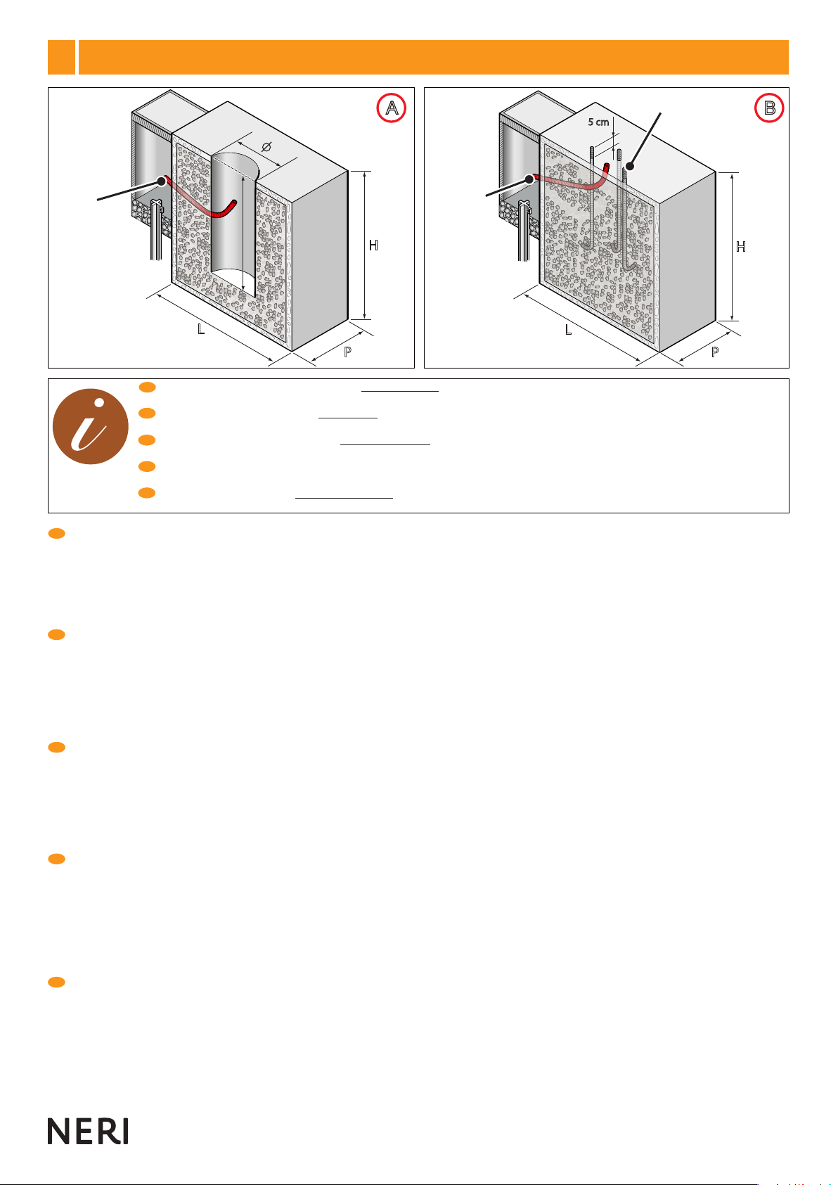
1) Il disegno di Fig. A, mostra la sezione di un plinto per pali con muratura. Nel centro del plinto và realizzato un foro con dimensioni (B,Ø) idonee all’inserimento
dell’anima del palo, la tabella a pag. 8 riporta tutte le dimensioni (altezza e diametro) delle anime pali con muratura. Il diametro (Ø) del foro ricavato nel plinto
dovrà essere circa 10 cm superiore al diametro della muratura dell’anima da installare. Predisporre un tubo essibile (P, diametro interno cm 5) in PVC,
per il passaggio dei cavi elettrici dal pozzetto di derivazione all’anima. 2) Il disegno di Fig. B, mostra la sezione di un plinto per pali con angia. Nel centro
del plinto vànno annegati i tirafondi (T), i disegni a pag. 9 e 14 riportano tutte le informazioni (fori, diametri, interassi) per il posizionamento. I tirafondi (T)
devono essere posizionati 5 cm più alti rispetto al livello (quota zero) di pavimentazione, e devono avere la parte sporgente lettata. Predisporre un tubo
essibile (G, diametro interno cm 5) in PVC, per il passaggio dei cavi elettrici dal pozzetto di derivazione all’anima, da posizionare al centro fra i tirafondi.
1) The drawing in Fig. Ashows the cross section of a plinth for cores to be cemented in. At the centre of the plinth there should be a hole (dimensions B,
Ø) suitable for insertion of the core. The chart on page 8 shows the relative dimensions (height and diameter) for all cores for cementing in. The hole
in the plinth should have diameter (Ø) at least 10 cm greater than the diameter of the base of the core to be installed. Prepare a exible PVC tube
and a second one (P, inside diameter 5 cm) for the passage of the electrical cables from the branch box to the core. 2) The drawing in Fig. B
shows the cross section of a plinth for cores with anges. Anchor bolts (T) must be sunk into the centre of the plinth; the drawings on pages 9
and 14 give all the relative information (holes, diameters, centre distances) for positioning of the anchor bolts. The anchor bolts (T) must be
positioned 5 cm higher than ground level (zero position), and the protruding sections must be threaded. Prepare a exible PVC tube (G, inside
diameter 5 cm) for the passage of electrical cables from the branch box to the core, to be positioned at the centre between the anchor bolts.
1) Le dessin de la Fig. A, montre la section d’un plinthe pour des candélabres à scellement direct. Le trou à réaliser au centre du plinthe doit avoir des
dimensions (B,Ø) appropriées pour l’introduction de l’âme du candélabre, le tableau à page 8 reporte toutes les dimensions (hauteur et diamètre) des âmes
des candélabres à scellement direct. Le diamètre (Ø) du trou pratiqué dans le plinthe devra être d’environ 10 cm supérieur au diamètre du scellement
de l’âme à installer. Prévoir un tube exible (P, diamètre interne 5 cm) en PVC, pour le passage des câbles électriques de la chambre de dérivation
à l’âme. 2) Le dessin de la Fig. B, montre la section d’un plinthe pour des candélabres avec bride. Les tire-fond (T) doivent être noyés toujours au centre
du plinthe, les dessins aux pages 9 et 14 reportent toutes les informations (trous, diamètres, entraxes) pour le positionnement correct. Les tire-fond (T)
doivent être positionnés 5 cm plus haut par rapport au niveau (cote zéro) du pavement et leur partie saillante doit être letée. Prévoir un tube exible
(G, diamètre interne 5 cm) en PVC, pour le passage des câbles électriques de la chambre de dérivation à l’âme, à positionner au centre entre les tire-fond.
1) Die Zeichnung in Abb. Azeigt den Schnitt eines Fundamentsockels für einzumauernde Pfähle. In der Mitte des Sockels wird ein Loch mit den Abmessungen
(B, Ø) belassen, die zur Einfügung der Pfahlseele nötig sind; die Tabelle auf Seite 8 liefert alle Abmessungen (Höhe und Durchmesser) der einzumauernden
Pfahlseelen. Der Durchmesser (Ø) der Öffnung im Sockel muss etwa 10 cm größer sein als der Einmauerungsdurchmesser der zu installierenden Seele.
Bereitstellen eines exiblen Rohrs (P, Innendurchmesser cm 5) aus PVC, zum Verlegen der elektrischen Kabel vom Verteilerschacht zum Mastkern. 2) Die
Zeichnung in Abb. Bzeigt den Schnitt eines Fundamentsockels für Pfähle mit Flansch. In der Mitte des Sockels werden ebenfalls die Ankerschrauben (T)
versenkt. Die Zeichnungen der Seiten 9 und 14 enthalten alle für das Positionieren notwendigen Informationen (Bohrungen, Durchmesser, Achsenabstände).
Die Bodenbefestigungseisendübel (T) müssen 5 cm hoch über Höhe Null des Pasters hinausragen und oben mit einem Gewinde versehen sein. Bereitstellen
eines exiblen Rohrs (G, Innendurchmesser cm 5) aus PVC zum Verlegen der elektrischen Kabel vom Verteilerschacht zum Mastkerns in der Mitte zwischen
den Ankerschrauben angebracht wird.
1) El dibujo de la Fig. A, muestra la sección de un plinto para postes con mampostería. En el centro del plinto se hace un agujero con dimensiones
idóneas (B, Ø) para introducir el alma del poste, la tabla de la pag. 8 presenta todas las dimensiones (altura y diámetro) de las almas de postes con
mampostería. El diámetro (Ø) del foro realizado en el plinto debe ser de unos 10 cm más grande que el diámetro de la mampostería del alma a
instalar. Preparar un tubo exible de PVC (P, diámetro interno 5 cm) para pasar los cables eléctricos desde el pozo de derivación al alma. 2) El dibujo
de la Fig. Bmuestra la sección de un plinto para postes con brida. Los tirafondos (T) se deben sumergir en el centro del plinto, consultar las guras de
las págs. 9 y 14 para conocer las medidas necesarias de instalación (oricios, diámetros, distancia entre ejes). Los tirafondos (T) se deben colocar
5 cm más altos con respecto al nivel (cota cero) del suelo, y deben tener la parte sobresaliente leteada. Preparar un tubo exible de PVC (G,
diámetro interior 5 cm), que se deberá colocar en el centro, entre los tirafondos, para pasar los cables eléctricos desde el pozo de derivación al alma.
PLINTO DI FONDAZIONE - CROSS SECTION - MASSIF D’ANCRAGE
FUNDAMENTSOCKEL - PLINTO DE CIMENTACIÓN
A B C
ATTENZIONE - CAUTION
ATTENTION - ACHTUNG
ATENCIÓN
12
13
www. neri.biz
9°
I
G B
F
D
E
IMBRACATURA PALO - POST SLINGING - ÉLINGAGE CANDÉLABRE - ANSCHLAG LICHTMAST -
ESLINGADO DEL POSTE
ATTENZIONE - Recintare la zona di lavoro. Se si utilizza un braccio meccanico per il sollevamento dell’anima (vedi tabella pesi e altezze anime a
pag. 6) attuare tutte le prescrizioni sull’uso in sicurezza di tale braccio. ATTENZIONE - Pericolo di oscillazione.
Per imbragare l’anima eseguire le istruzioni sotto elencate: 1) Munirsi di un cavo in acciaio senza ganci con portata non inferiore a 250 Kg e di lunghezza idonea
(vedi altezza anima a pag. 6). 2) Inserire il cavo all’interno dell’asola sede morsettiera (Fig. B). 3) Eseguire un nodo all’estremità inferiore del cavo di acciaio (Fig.
B). 4) Fare un cappio all’estremità superiore del cavo e ssare il tutto con due morsetti per cavi metallici (Fig. C).
IMPORTANTE - Se l’anima è verniciata nella zona in cui è a contatto con il cavo, interporre fra il cavo e l’anima degli strati di cartone per proteggere
la verniciatura.
5) Agganciare il cappio al gancio del braccio meccanico e sollevare lentamente l’anima.
CAUTION - Fence off the work area. If a crane is used to lift the core (see chart with weights on page 6) take all precautions for the safe use of this
equipment. CAUTION: Danger of swinging objects.
To secure the core to be lifted follow these instructions: 1) Procure a steel cable without hooks, with a lifting capacity of at least 250 kg and of a suitable length
(see core heights on page 6). 2) Insert the cable through the terminal board seat slot (Fig. B). 3) Make a knot at the lower end of the steel cable (Fig. B). 4) Make
a loop at the upper end of the cable and secure it with two metal cable U-clamps (Fig. C).
IMPORTANT - If the core is painted at the point where the cable is wound, place layers of cardboard between the core and the cable to protect the paintwork.
5) Attach the loop to the crane hook and slowly lift the core.
ATTENTION - Délimiter la zone de travail. Dans le cas d’utilisation d’un bras mécanique pour le levage de l’âme (voir tableau poids et hauteurs
des âmes à pag. 6) respecter toutes les prescriptions de sécurité concernant l’utilisation de ces appareils. ATTENTION, risque d’oscillations.
Pour élinguer l’âme, suivre les instructions suivantes: 1) S’équiper d’un câble en acier sans crochets d’une portée non inférieure à 250 kg et de
longueur appropriée (voir hauteur des âmes à pag. 6). 2) Introduire le câble à l’intérieur de la fente (Fig. B). 3) Réaliser un noeud à l’extrémité inférieure
du câble en acier (Fig. B). 4) Faire un noeud coulant à l’extrémité supérieure du câble et xer le tout avec deux bornes pour câbles métalliques (Fig. C)
.
IMPORTANT - Si l’âme est peinte dans la zone de contact avec le câble, il est nécessaire de placer des feuilles de carton entre le câble même et
l’âme, an de protéger la peinture.
5) Accrocher le noeud coulant au crochet du bras mécanique et soulevet lentement l’âme.
ACHTUNG - Den Arbeitsbereich absperren. Wenn ein mechanischer Arm zur Anhebung der Seele benutzt wird (siehe Tabelle der Gewichte und
Längen der Seelen auf Seite 6) alle Sicherheitsvorschriften für den Einsatz dieses Arms anwenden. ACHTUNG, Schwingungsgefahr.
Zum Anschirren der Elemente den u.a. Anweisungen folgen: 1) Man verwende ein Stahlseil ohne Haken für ein Gewicht von nicht weniger als 250 kg und
eine hinreichende Länge (siehe die Höhe der Seele auf Seite 6). 2) Das Kabel in das Langloch des Klemmenbretts (Abb. B) einführen. 3) Einen Knoten am
unteren Ende des Stahlkabels (Abb. B) erstellen. 4) Eine Schlaufe am oberen Kabelende bilden und das Ganze mit zwei Metallkabelklemmen (Abb. C) befestigen.
WICHTIG - Falls die Seele in diesem Bereich lackiert ist, zwischen Seil und Seele Kartonstreifen schieben, um die Lackierung zu schützen.
5) Die Schlinge am Haken des mechanischen Arms einhängen und den Mastkern langsam anheben.
ATENCIÓN - Delimitar la zona de trabajo. Si se utiliza un brazo mecánico para elevar el alma (véase la tabla de pesos y alturas en la pág. 6),
respetar las normas de uso para utilizar el brazo de modo seguro. ATENCIÓN: peligro de oscilación.
Para eslingar el alma, respetar las siguientes instrucciones: 1) Utilizar un cable de acero sin ganchos con capacidad para soportar cargas de más de 250 kg y que
posea una longitud adecuada (véase la altura del alma en la pág. 6). 2) Introducir el cable dentro del ojal situado en la regleta (Fig. B). 3) Realizar un nudo en
el extremo inferior del cable de acero (Fig. B). 4) Realizar un lazo en el extremo superior del cable y jar el tubo con dos anclajes para cables metálicos (Fig. C).
IMPORTANTE:Silazonadelalmaencontactoconelcableestápintada,colocarentreelcableyelalmavariosestratosdecartónparaprotegerlapintura.
5) Enganchar el lazo al gancho del brazo mecánico y levantar lentamente el alma.
A
14
15
10°
I
G B
F
D
E
Orientare la cima con l’asola nella posizione più compatibile alla carreggiata stradale. Per agevolare le operazioni di manutenzione, l’orientamento
dovrà essere effettuato verso il lato marciapiede. Nell’eventualità ci siano impedimenti oppure ostacoli l’orientamento dovrà essere effettuato verso
il lato carreggiata.
Move the top section with the slot to the position which is most compatible with the roadway. To facilitate maintenance operations, the slot should
be facing the pavement. In the event of any impediments or obstacles, the slot must face towards the roadway.
Orienter le bouquet avec la fente dans la position la plus compatible avec la chaussée routière. Pour faciliter les opérations d’entretien, l’orientation
devra être effectuée vers le côté trottoir. Dans l’éventualité qu’il y ait des empêchements ou des obstacles, l’orientation devra être effectuée vers
le côté chaussée.
Das obere Ende mit dem Langloch richtig zur Fahrbahn ausrichten. Um die Wartungsarbeiten zu erleichtern, das Langloch zum Bürgersteig hin
ausrichten. Sollte dies wegen Hindernissen oder anderen Problemen nicht möglich sein, das Langloch zur Fahrbahn hin ausrichten.
Orientar la cima con el ojal hacia la posición más compatible con la vía urbana. Para facilitar las operaciones de mantenimiento, se deberá orientar
hacia el lado de la acera. Si no fuera posible, se deberá orientar hacia el lado de la calzada.
INSTALLAZIONE ANIME PALI - POST CORES INSTALLATION - INSTALLATION ÂMES CANDÉLABRES -
INSTALLATION MASTKERNE - INSTALACIÓN DE LAS ALMAS EN LOS POSTES
B C
14
15
www. neri.biz
10°
I
G B
F
D
E
ATTENZIONE - Recintare la zona di lavoro, pericolo di oscillazioni. Se si utilizza un braccio meccanico per il sollevamento dell’anima
eseguire le operazioni di imbracatura descritte al capitolo 9 (pag. 13).
Per l’installazione di anime con muratura eseguire le sottostanti operazioni:
1) Vericare che il plinto sia ben consolidato. Molto lentamente e delicatamente in modo da non danneggiare l’anima, inlarla nel foro del plinto inserendo il tubo
essibile, per il passaggio dei cavi elettrici, nell’asola dell’anima stessa.
2) Vericare la corretta posizione delle asole rispetto alla carreggiata stradale (vedi pag.14). Livellare l’anima vericando che la tacca di riferimento quota zero
(segnalata sull’anima) corrisponda al piano di pavimentazione nale (Fig. B). L’anima deve essere posizionata perfettamente a piombo (Fig. B).
3) A questo punto ssarla con una colata di cemento a presa rapida riempendo il foro del plinto rimasto libero (Fig. C). Liberare l’anima dall’imbracatura.
CAUTION- Fenceofftheworkarea.Dangerofswingingobjects.Ifacraneisusedtoliftthecore,secureliftingcableasdescribedinsection10(page13).
To install cores for cementing in proceed as follows:
1) Check that the plinth has hardened sufciently. Very slowly and carefully, in such a way as to avoid damage to the core, insert the core into the plinth, inserting
the exible hose for entry of the electrical cables into the core slot.
2) Check that the slots are in the correct position with respect to the roadway (see page 14). Level the core, checking that the zero position reference mark (on
the core) corresponds with the nal paving level (Fig. B). The core must be positioned so that it is perfectly vertical (Fig. B).
3) Now secure the core by lling the gap around the base with quick-setting cement (Fig. C). Free the core from the lifting cable.
ATTENTION - Délimiter la zone de travail, risque d’oscillations. Dans le cas d’utilisation d’un bras mécanique pour le levage de l’âme, effectuer
les opérations d’élingage décrites au chapitre 10 (pag. 13).
Pour l’installation d’âmes à scellement direct, effectuer les opérations suivantes:
1) Vérier que le massif d’ancrage soit bien consolidé. Introduire très lentement et délicatement l’âme dans le trou du plinthe an d’éviter tout endommagement,
en introduisant le tube exible, pour le passage des câbles électriques, dans la fente de l’âme même.
2) Vérier la juste position des boutonnières par rapport à la chaussée (voir pag. 14). Niveler l’âme en vériant que le repère de cote zéro (indiqué sur l’âme)
corresponde au plan de pavement nal (Fig. B). L’âme doit être installée dans une position parfaitement verticale (Fig. B).
3) Fixer à présent l’âme à l’aide d’une coulée de ciment à prise rapide en remplissant l’espace resté libre dans le trou du plinthe (Fig. C). Libérer l’âme de l’élingue.
ACHTUNG - Den Arbeitsbereich absperren, Schwingungsgefahr. Wenn man einen mechanischen Arm zum Anheben der Seele benutzt, muss
man die Anschirrarbeiten durchführen, wie sie im Kapitel 10 (Seite 13) beschrieben sind.
Zur Installation der einzumauernden Seelen führt man die folgenden Operationen durch:
1) Überprüfen, dass der Sockel fest geworden ist. Um Beschädigungen zu vermeiden, den Mastkern sehr langsam und vorsichtig in die Bohrung des Sockels
und das exible Rohr zum Verlegen der elektrischen Kabel im Langloch des Mastkerns selbst, einführen.
2) Die korrekte Positionierung der Öffnungen im Verhältnis zur Fahrbahn überprüfen (siehe Seite 14). Den Mastkern nivellieren indem geprüft wird, dass die
Bezugskerbe Nullhöhe (auf dem Mastkern angegeben) mit der Endbodenäche übereinstimmt (Abb. B). Der Mastkern muss perfekt senkrecht (Abb. B)
ausgerichtet sein.
3) Diesen dann, durch Auffüllen des Freiraums der Sockelbohrung, mit einem Schnellzementguss befestigen (Abb. C). Die Seele vom Geschirr lösen.
ATENCIÓN - Recintar la zona de trabajo, peligro de oscilación. Si se utiliza un brazo mecánico para la elevación del alma, seguir las operaciones
de eslingado descritas en el cap. 10 (pág. 13).
Para la instalación de almas con mampostería realizar las operaciones siguientes:
1) Comprobar que el plinto esté bien consolidado. Muy lenta y delicadamente para no dañarla, introducir el alma en el agujero del plinto y el tubo exible para
pasar los cables eléctricos por el ojal del alma.
2) Comprobar la correcta posición de los ojales con respecto a la calzada (vean pág. 14). Nivelar el alma comprobando que la muesca de referencia de cota
cero (marcada en el alma) coincida con el nivel del pavimento nal (Fig. B). El alma debe colocarse en posición perfectamente vertical (Fig. B).
3) Ahora, jar el ama con una colada de cemento de secado rápido, llenando el agujero del plinto que está libre (Fig. C). Liberar el alma de la eslinga.
INSTALLAZIONE ANIME PALI - POST CORES INSTALLATION - INSTALLATION ÂMES CANDÉLABRES -
INSTALLATION MASTKERNE - INSTALACIÓN DE LAS ALMAS EN LOS POSTES
CM
D E
16
17
10°
I
G B
F
D
E
ATTENZIONE - Recintare la zona di lavoro, pericolo di oscillazioni. Se si utilizza un braccio meccanico per il sollevamento dell’anima
eseguire le operazioni di imbracatura descritte al capitolo 9 (pag. 13).
Per l’installazione di anime con angia eseguire le sottostanti operazioni:
1) Vericare che il plinto sia ben consolidato e i tirafondi ben solidali con esso. Utilizzare per i tirafondi solo viti in acciaio inox o zincate.
2) Vericare la corretta sporgenza (5 cm) (Fig. D) e posizionamento dei tirafondi (vedi disegno della angia a pag. 9).
3)Molto lentamente e delicatamente in modo da non danneggiare i tirafondi, inserire l’anima con angia sopra di essi. L’anima deve essere posizionata perfettamente
a piombo (Fig. E). La quota della pavimentazione nale e la angia devono essere allo stesso livello (Fig. E). Fissare saldamente l’anima ai tirafondi con le viti.
Liberare l’anima dall’imbracatura.
CAUTION-Fenceofftheworkarea.Dangerofswingingobjects.Ifacraneisusedtoliftthecore,secureliftingcableasdescribedinsection10(page13).
To install cores with ange proceed as follows:
1) Check that the plinth has hardened sufciently and that the anchor bolts are rmly embedded. For anchor bolts use only stainless steel or galvanized nuts.
2) Check for correct protrusion (5 cm) (Fig. D) and positioning of the anchor bolts (see drawing of ange on page 9).
3) Very gradually and carefully, in such a way as to avoid damaging the anchor bolts, lower the core with ange over the bolts. The core must be positioned so that
it is perfectly upright (Fig. E). The height of the nal paving and the ange must be at the same level (Fig. E). Firmly secure the core to the anchor bolts with
nuts. Free the core from the lifting cable.
ATTENTION - Délimiter la zone de travail, risque d’oscillations. Dans le cas d’utilisation d’un bras mécanique pour le levage de l’âme, effectuer les
opérations d’élingage décrites au chapitre 10 (pag. 13).
Pour l’installation d’âmes à semelle de xation, effectuer les opérations suivantes:
1) Vérier que le massif d’ancrage soit bien consolidé et que les tige ascellement soient bien xés. Pour les tige ascellement, n’utiliser que des vis en acier
inox ou zinguées.
2) Vérier la correcte saillie (5 cm) (Fig. D) et le positionnement des tire-fond (voir dessin de la bride à la page 9).
3) Introduire lentement et délicatement l’âme avec bride sur les tire-fond, an de ne pas les endommager. L’âme doit être installée dans une position parfaitement
verticale (Fig. E). La cote du pavement nal et la bride doivent être au même niveau (Fig. E). Fixer solidement l’âme aux tire-fond avec les vis. Libérer l’âme
de l’élingue.
ACHTUNG - Den Arbeitsbereich absperren, Schwingungsgefahr. Wenn man einen mechanischen Arm zum Anheben der Seele benutzt, muss man
die Anschirrarbeiten durchführen, wie sie im Kapitel 10 (Seite 13) beschrieben sind.
Zur Installation der Seelen mit Flansch führt man die folgenden Operationen durch:
1) Überprüfen, dass der Sockel fest geworden ist und die Bodenbefestigungseisendübel darin fest verankert sind. Nur Bodenbefestigungseisendübel aus
Edelstahl oder verzinktem Stahl verwenden.
2) Überprüfen, dass die Ankerschrauben weit genug herausragen (5 cm) (Abb. D) und richtig positioniert sind (siehe Flansch-Zeichnung auf Seite 9).
3) Um die Ankerschrauben nicht zu beschädigen, den Mastkern mit Flansch ganz langsam und vorsichtig einführen. Der Mastkern muss perfekt senkrecht (Abb.
E) ausgerichtet sein. Die Oberkante des Bodenbelags und der Flansch müssen sich auf derselben Höhe benden (Abb. E). Mittels der Schrauben die Seele
an den Bodenbefestigungseisendübeln befestigen. Die Seele vom Geschirr lösen.
ATENCIÓN - Recintar la zona de trabajo, peligro de oscilación. Si se utiliza un brazo mecánico para la elevación del alma, seguir las operaciones
de eslingado descritas en el cap. 10 (pag 13).
Para la instalación de almas con brida realizar las operaciones siguientes:
1) Comprobar que el plinto esté bien consolidado y los tirafondos bien jados al mismo. Utilizar para los tirafondos sólo tornillos de acero inox o cincados.
2) Comprobar que los tirafondos sobresalgan (5 cm) (Fig. D) y estén colocados correctamente (ver la gura de la brida en la pág. 9).
3) Introducir el alma con brida sobre los tirafondos muy lenta y delicadamente para no dañarlos. El alma debe colocarse en posición perfectamente vertical (Fig.
E). Las cotas del pavimento nal y de la brida deben estar al mismo nivel (Fig. E). Fijar fuertemente el alma a los tirafondos con los tornillos. Liberar el alma de
la eslinga.
Nota: tirafondi e dadi non forniti
Note: anchor bolts and nuts are not supplied
Note: tire-fond et écrous non fournis
Hinweis: Die Ankerschrauben und Muttern gehören nicht
zum Lieferumfang.
Nota: los tirafondos y las tuercas no se suministran de
fábrica.
INSTALLAZIONE ANIME PALI - POST CORES INSTALLATION - INSTALLATION ÂMES CANDÉLABRES -
INSTALLATION MASTKERNE - INSTALACIÓN DE LAS ALMAS EN LOS POSTES
A B
16
17
www. neri.biz
11°
I
G B
F
D
E
IMPORTANTE - Se l’impianto elettrico prescrive il collegamento a terra del palo, procedere utilizzando l’apposita vite M10 in acciaio inox posta all’interno
dell’asola porta morsettiera dell’anima (Fig. A) e contrassegnata dal simbolo di messa a terra.
Il collegamento a terra (Fig. B), se da eseguire, và effettuato nel momento in cui si procede al piazzamento del palo.
IMPORTANT - If the electrical system prescribes connecting the post to earth, proceed using the relative M10 stainless steel screw located inside the core’s
terminal board holder slot (Fig. A) and marked with the earthing symbol.
The earthing connection (Fig. B), if required, must be executed when post positioning is performed.
IMPORTANT - Si l’instalation électrique prévoit la connexion à la terre du candélabre, il est conseillé de procéder en utilisant la vis M10 en acier inox placée
à cet effet à l’intérieur de la fente bornier de l’âme (Fig. A) et marquée du symbole de mise à la terre.
La connexion à la terre (Fig. B), le cas échéant, doit être effectuée au moment du positionnement du candélabre.
WICHTIG - Wenn für die elektrischeAnlage die Erdung des Masts vorgeschrieben ist, hierzu die mit dem Symbol für die Schutzerdung gekennzeichnete
Edelstahlschraube M10 im Langloch für die Klemmenleiste des Mastrohrs verwenden (Abb. B).
Die Erdverbindung (Abb. B) muss, falls vorgeschrieben, in dem Moment hergestellt werden, in dem der Mast aufgestellt wird.
IMPORTANTE - Si para realizar la instalación eléctrica es necesario conectar el poste a tierra, utilizar el tornillo M10 de acero inoxidable situado dentro del
ojal de alojamiento de la regleta del alma (Fig. A) y marcado con el símbolo de puesta a tierra.
La conexión a tierra (Fig. B) se debe realizar al instalar el poste.
MESSA A TERRA - GROUND CONNECTION - MISE A LA TERRE - ERDUNG - COLOCACIÓN EN TIERRA
A B
12°
I
G B
F
D
E
IMPORTANTE - Al termine dell’installazione delle anime con angia vericare scrupolosamente il serraggio dei dadi dei tirafondi (Fig. A).
Proteggere con prodotti contro la corrosione (vernici a base di zinco, grasso, ecc.) i dadi e le lettature dei tirafondi (Fig. B).
I tirafondi, i dadi e i prodotti protettivi non sono forniti.
IMPORTANT - After the installation of cores with anges, scrupulously check that the nuts on the anchor bolts have been fully tightened (Fig. A).
Protect nuts and anchor bolt threads with anti-corrosion products (zinc paint, grease, etc) (Fig. B).
Anchor bolts, nuts and anti-corrosion products are not supplied.
IMPORTANT - Au terme de l’installation des âmes à semelle de xation, contrôler scrupuleusement le serrage des écrous des tige ascellement (Fig. A).
Protéger les écrous et les letages des tige ascellement par des produits contre la corrosion (peintures à base de zinc, gras, etc.) (Fig. B).
Les tige ascellement, les vis et les produits de protection ne sont pas fournis.
WICHTIG - Nach Beendigung der Installation der Seelen mit Flansch sorgfältig überprüfen, dass die Muttern der Bodenbefestigungseisendübel fest
angezogen sind (Fig. A).
Die Muttern und die Gewinde der Bodenbefestigungseisen mit Anti-Korrosionsprodukten schützen (Lacke auf Zinkbasis, Fett usw.) (Abb. B).
Die Bodenbefestigungseisendübel, die Muttern und die Schutzprodukte werden nicht mitgeliefert.
IMPORTANTE - Al nalizar la instalación de las almas con brida, comprobar esmeradamente el cierre de los tuercas tirafondos (Fig. A).
Proteger con productos anticorrosivos (pinturas de cinc, grasa, etc...) las tuercas y los leteados de los tirafondos (Fig. B).
Los tirafondos, tuercas y productos protectores no se suministran de fábrica.
PROTEZIONI FINALI - FINAL PROTECTION - PROTECTIONS FINALES - SCHUTZBEHANDLUNG -
PROTECCIÓN FINAL
18
19
326mc
327mc
328mc
326mc
327mc
328mc
326mc
327mc
328mc
1°
4°
1°
4°
8300.500.100
8300.500.200
8300.501.100
8300.501.200
8300.600.100
8300.600.200
8300.601.100
8300.601.200
8300.700.100
8300.700.200
8300.701.100
8300.701.200
1°
4°
Rif. CODICE
CODE - CODE
CODE - CÓDIGO Kg
1°
2°
3°
4°
9525.322.010
9501.184
9545.100
0001.014
17,50
10,50
3,05
1,34
Cod.
Rif.
2° - 3° 2° - 3° 2° - 3°
18
19
www. neri.biz
TABELLA CODICE, PESO, RIFERIMENTO - CODE, WEIGHT, REFERENCE TABLE - TABLEAU CODE, POIDS, RÉFÉRENCE -
TABELLE CODE, GEWICHT, BEZUG - TABLA DE CÓDIGOS, PESOS Y REFERENCIAS
Ghisa
Cast iron
Fonte
Gusseisen
Hierro fundido
Acciaio inox
Stainless steel
Acier inox
Edelstahl
Acero inoxidable
A
D E F
B C
ATTENZIONE PERICOLO
CAUTION : DANGER
ATTENTION DANGER
ACHTUNG GEFAHR
ATENCIÓN, PELIGRO
20
21
13°
I
G B
F
D
E
Per il disimballo degli elementi (in base al tipo di imballo omettere ciò che non serve) comportarsi nel seguente modo:
1) predisporre a terra una robusta stuoia per proteggere le parti verniciate (Fig. A);
2) togliere il nylon di protezione e tagliare le centine (Fig. B) (ATTENZIONE pericolo di schiacciamento);
3) non trascinare o rotolare gli elementi a terra, ma porli sulla stuoia (Fig. C);
4) non usare taglierini o lame per togliere l’imballo, si potrebbe danneggiare la verniciatura (Fig. D), manualmente togliere il nastro adesivo dagli imballi;
5) utilizzare una pinza per togliere i punti metallici dalle scatole (Fig. E): ATTENZIONE a non disperderli nell’ambiente;
ATTENZIONE - La non osservanza delle prescrizioni citate sopra aumenta il rischio di incidenti.
IMPORTANTE - Non disperdere l’imballo nell’ambiente, potrebbe essere fonte di pericolo e inquinamento (Fig. F). Seguire le normali procedure di
smaltimento dei riuti urbani in conformità alle norme vigenti.
To unpack, proceed as follows (disregard instructions that do not apply to type of packing received):
1) Lay a robust mat on ground to protect paintwork (Fig. A).
2) Remove protective plastic and cut strapping (Fig. B) (Caution: risk of crushing injury).
3) Do not drag or roll elements on ground, but place on mat (Fig. C);
4) do not use knives or other blades to remove packing materials, as this could damage paintwork (Fig. D), but remove adhesive tape from packing by hand.
5) use a pair of pliers to remove the metal staples from the cartons (Fig. E): WARNING: dispose of the removed staples properly.
CAUTION – Failure to apply the above precautions will increase the risk of accidents.
IMPORTANT – Do not dispose incorrectly of packaging materials, which could be a source of pollution and danger (Fig. F).Follow normal waste
disposal procedures for urban wastes in compliance with applicable legislation.
Pour le déballage des éléments, (en fonction du type d’emballage, omettre les précisations inutiles), suivre les indications suivantes:
1) étendre sur le sol une natte robuste pour protéger les parties peintes (Fig. A);
2) enlever le lm de protection et couper les bandes de cerclage (Fig. B) (Attention risque d’écrasement);
3) ne pas traîner ou faire rouler les éléments sur le sol mais les placer sur la natte (Fig. C);
4) pour enlever l’emballage, ne pas utiliser de coupoirs ou de lames qui risqueraient d’endommager la peinture (Fig. D), mais ôter le ruban adhésif des emballages
manuellement;
5) utiliser une pince pour retirer les points métalliques des boîtes (Fig. E) : ATTENTION - Ne pas les disperser dans l’environnement.
ATTENTION - La non-observation des prescriptions citées ci-dessus augmente le risque d’accidents.
IMPORTANT - Déposer l’emballage dans un lieu de collecte approprié, pour éviter tout danger ou pollution de l’environnement (Fig. F). Suivre les
normales procédures de collecte des ordures urbaines conformément aux normes en vigueur.
Beim Auspacken der Elemente (auf Basis des Verpackungstyps das weglassen, was nicht dienlich ist) muss man wie folgt vorgehen:
1) auf dem Boden eine robuste Matte zum Schutz der lackierten Teile ausbreiten (Abb. A);
2) die Nylonfolie entfernen und die Haltebänder durchtrennen (Abb. B) (Achtung, es besteht Quetschgefahr);
3) die Elemente nicht auf die Erde ziehen oder rollen, sondern auf die Matte aufsetzen (Abb. C);
4) keine Schneidewerkzeuge zur Entfernung der Verpackung benutzen, man könnte sonst die Lackierung beschädigen (Abb. D), die Klebelme von Hand entfernen;
5) Die Klammern an den Schachteln (Abb. E) mit einer Zange entfernen. ACHTUNG! Sie nicht im Freien entsorgen.
ACHTUNG - Die Nichtbeachtung dieser Anweisungen erhöht das Unfallrisiko.
WICHTIG -Die Verpackung nicht in der Umgebung liegen lassen, sie könnte eine Gefahrenquelle sein und die Umwelt verschmutzen (Abb. F).
Folgen Sie den normalen Verfahren zur Beseitigung von städtischenAbfällen entsprechend den geltenden Vorschriften.
Para desembalar los elementos (según el tipo de embalaje, omitir lo que no sirve), realizar las siguientes operaciones:
1) Colocar en el suelo una estera gruesa para proteger las partes pintadas (Fig. A);
2) Quitar el nilón protector y cortar las tiras envolventes (Fig. B) (atención: peligro de aplastamiento);
3) No arrastrar ni hacer rodar los elementos por el suelo, se deben colocar sobre la estera (Fig. C);
4) No usar cuchillos ni cuchillas para cortar el embalaje, pues podrían raspar la pintura (Fig. D), retirar manualmente la cinta adhesiva de los embalajes;
5) Utilizar unos alicates para quitar las grapas de las cajas (Fig. E): ATENCIÓN - no abandonarlas en el medio ambiente.
ATENCIÓN- El no observar las normas de seguridad citadas anteriormente implica aumentar el riesgo de accidentes.
IMPORTANTE - No abandonar el embalaje, podría resultar fuente de peligro o de contaminación (Fig. F). Seguir el procedimiento normal de retirada
de la basura urbana según las leyes vigentes.
DISIMBALLO - UNPACKING - DEBALLAGE - AUSPACKEN - DESEMBALAJE

Other NERI Outdoor Light manuals

NERI CASTORE 1161.015 User manual

NERI

NERI CASTORE 1161.015 User manual

NERI Nebula BONEB Operating and maintenance instructions

NERI

NERI Nebula BONEB Operating and maintenance instructions

NERI LIGHT 804 User manual

NERI

NERI LIGHT 804 User manual

NERI LIGHT 100 User manual

NERI

NERI LIGHT 100 User manual

NERI LIGHT 21 Operating and maintenance instructions

NERI

NERI LIGHT 21 Operating and maintenance instructions

NERI LIGHT 700 User manual

NERI

NERI LIGHT 700 User manual

NERI LIGHT 600 User manual

NERI

NERI LIGHT 600 User manual

NERI LIGHT 104 User manual

NERI

NERI LIGHT 104 User manual

NERI Nashira 1191.050 User manual

NERI

NERI Nashira 1191.050 User manual

NERI Nebula Bollard Operating and maintenance instructions

NERI

NERI Nebula Bollard Operating and maintenance instructions

NERI LIGHT 103 Operating and maintenance instructions

NERI

NERI LIGHT 103 Operating and maintenance instructions

NERI Pictor Bollards Operating and maintenance instructions

NERI

NERI Pictor Bollards Operating and maintenance instructions

NERI Brenta bollards Operating and maintenance instructions

NERI

NERI Brenta bollards Operating and maintenance instructions

NERI 853 Series User manual

NERI

NERI 853 Series User manual

NERI Altair HERON Series User manual

NERI

NERI Altair HERON Series User manual

NERI LIGHT 801 Series User manual

NERI

NERI LIGHT 801 Series User manual

NERI Pictor Operating and maintenance instructions

NERI

NERI Pictor Operating and maintenance instructions

NERI Nebula S Operating and maintenance instructions

NERI

NERI Nebula S Operating and maintenance instructions

NERI LIGHT 104 User manual

NERI

NERI LIGHT 104 User manual

Popular Outdoor Light manuals by other brands

JONATHAN Y JYL6123A quick start guide

JONATHAN Y

JONATHAN Y JYL6123A quick start guide

LIGMAN LIGHT LINEAR PT-X 16 installation manual

LIGMAN

LIGMAN LIGHT LINEAR PT-X 16 installation manual

Addington Park 30812091 quick guide

Addington Park

Addington Park 30812091 quick guide

Kichler Lighting 15317AZT quick start guide

Kichler Lighting

Kichler Lighting 15317AZT quick start guide

Westinghouse Pinta owner's manual

Westinghouse

Westinghouse Pinta owner's manual

SLV Elektronik NAUTILUS GX53 operating manual

SLV Elektronik

SLV Elektronik NAUTILUS GX53 operating manual

Knightsbridge SPIKE4BK Installation & maintenance manual

Knightsbridge

Knightsbridge SPIKE4BK Installation & maintenance manual

ABBA UNB02 installation guide

ABBA

ABBA UNB02 installation guide

Malmbergs 99 740 56 instruction manual

Malmbergs

Malmbergs 99 740 56 instruction manual

Trebs Comfortlight M-6017 manual

Trebs

Trebs Comfortlight M-6017 manual

Living & Co E27 25W instructions

Living & Co

Living & Co E27 25W instructions

Belux LEIA-10 Assembly instructions

Belux

Belux LEIA-10 Assembly instructions

Faro BOO manual

Faro

Faro BOO manual

Qazqa Empoli FL Satin CCT 2 instruction manual

Qazqa

Qazqa Empoli FL Satin CCT 2 instruction manual

Safavieh TBL4386A Assembly instructions

Safavieh

Safavieh TBL4386A Assembly instructions

Zafferano ofelia pro Instructions for use

Zafferano

Zafferano ofelia pro Instructions for use

Kichler Lighting 59009WZC quick start guide

Kichler Lighting

Kichler Lighting 59009WZC quick start guide

Cattelan Italia KARIBU Assembling instructions

Cattelan Italia

Cattelan Italia KARIBU Assembling instructions

manuals.online logo
manuals.online logoBrands
  • About & Mission
  • Contact us
  • Privacy Policy
  • Terms and Conditions

Copyright 2025 Manuals.Online. All Rights Reserved.