Page 6
Closing Power Adjustment–
Control Valve Adjustments
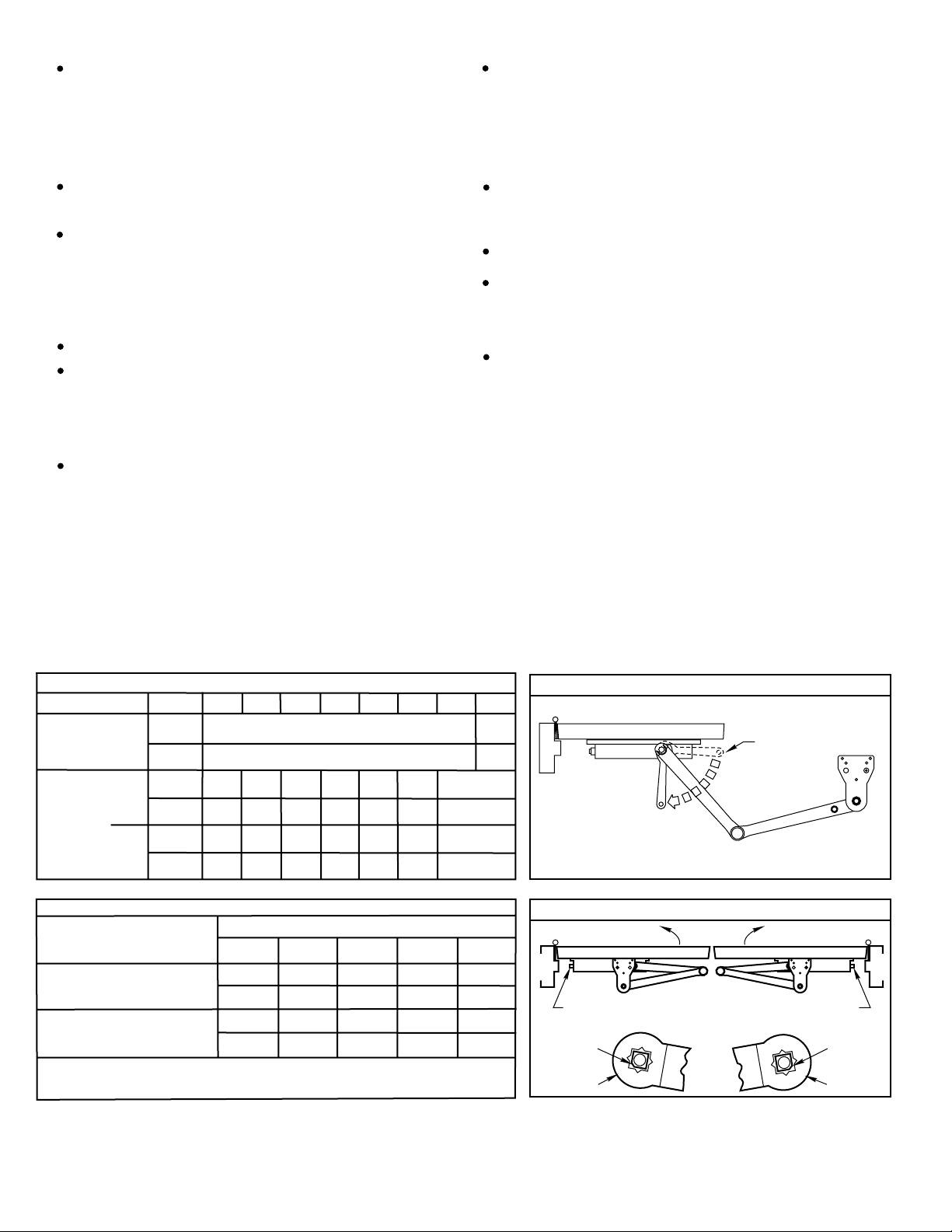
Closing Speed Controls (Figure 1A or 1B and 2.)
Using “Power Adjustment Chart”from Page 3, select the
correct number of turns for power adjustment shaft that
corresponds with the installation. With 1/8”hex-key provided,
rotate adjustment shaft full 360°clockwise turns to desired
setting. After closer has been installed and proper
adjustments made to the sweep and latch, it may be
necessary to readjust spring power for good closing action.
(See Figure 2.)
Valve “S”Controls Sweep Range.
Valve “L”Controls Latch Range.
Valve “D”Controls Delay Range (optional).
Unit Adjustment
L
A
T
C
H
L
A
T
C
H
Delayed Action
Closing Cycle
1B
Closing Speed Controls Figure 1.
S
W
E
E
P
S
W
E
E
P
Attention : Adjust Closing Speed Time
to between 4 to 7 seconds from 90°.
Use of the door by handicapped,
elderly or small children may require
greater closing time.
CLOSED
CLOSED
Standard Closing Cycle
1A
D
E
L
A
Y
R
A
N
G
E
10°
10°
70°
CAUTION:
DO NOT BACK VALVES OUT OF
CLOSER OR A LEAK WILL
RESULT.
Closing Speed Controls Figure 2.
Slow
1/8”
Hex
Key
Fast
Latch
Valve
Sweep
Valve
Delay Valve
Closing Power Control Figure 3.
Opening Cycle
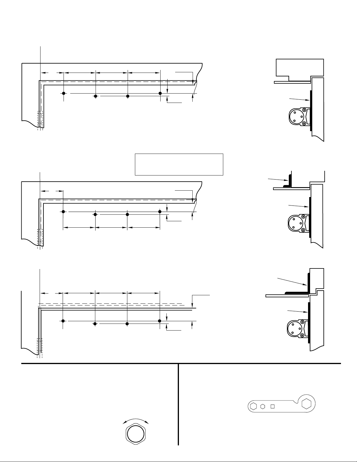
Cover–
“Backcheck”valve controls the strength of cushioning in
Backcheck Range. NEVER close this valve completely –it
is not to provide a positive stop. (see Figure 4 and Figure 5).
Full cover: Slide cover insert into the un-used cutout
in cover. Install cover using screws provided.
Narrow cover: Install cover using screws provided. Install
pinion cap onto pinion shaft by hand or with a Phillips screw
driver - DO NOT OVER TIGHTEN.
Metal cover: Fasten cover to mounting clips with screws
provided.
Architectural Metal Cover: Remove cover insert where
pinion is located. Install standoffs in ends of closer. Install
cover using screws provided.
Architectural Plastic Cover: Slide cover insert into the un-
used cutout in cover. Install standoffs in ends of closer.
Snap cover over standoffs.
.
Slow
1/8”
Hex
Key
Fast
Slow
1/8”
Hex
Key
Fast
1902 Airport Road, Monroe, NC
Telephone:(800)-438-1951; Fax: (800)-338-0965
www.yalesecurity.com
Security Group
O
P
E
N
I
N
G
Opening Door Control Figure 4.
Opening Cycle
B
A
C
K
C
H
ECK
CAUTION:
DO NOT BACK VALVES OUT OF
CLOSER OR A LEAK WILL
RESULT.
Decrease
Increase
Backcheck Control Figure 5.
Backcheck Valve*
1/8”
Hex
Key
Decrease
Increase
5/16”Socket
or Adjustable Wrench
Power Adjustment Shaft
NOTE: Maximum of 20 360°turns
of Power Adjustment Shaft
NEVER CLOSE VALVES
COMPLETELY - NOT
INTENDED TO PROVIDE
A POSITIVE STOP.
Cover Mounting Figure 6.
An ASSA ABLOY Group Co.