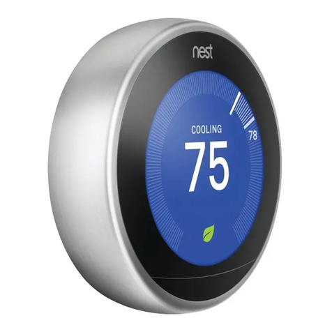
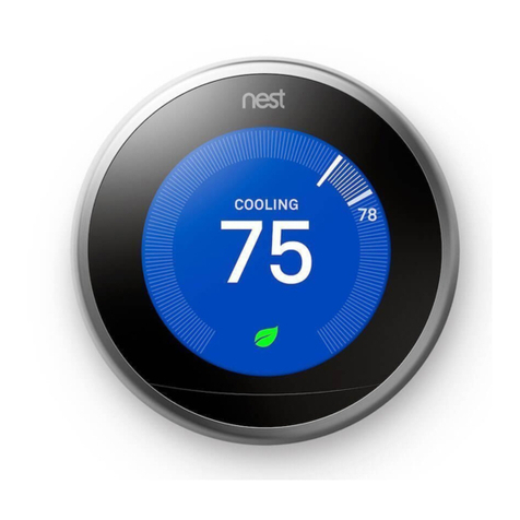
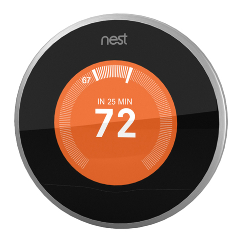
nest Learning thermostat Operator's manual

Nest Learning Thermostat
Pro installation & configuration guide
Need help?
•Help online: http://support.nest.com/certified
•Nest Certified Professional support: 1-855-VIP-NEST (1-855-847-6378)
•Hours: 5am-9pm (pacific), 8am-midnight (eastern).
Last updated: April 17, 2013
Version: 2.0

Table of Contents
Installation overview 1
What’s different about installing Nest 1
Installation check-list 1
Installation details 2
Technical specifications 4
Supported wiring 6
Wiring diagrams: Conventional Systems 8
Wiring diagrams: Heat Pump Systems 12
Wiring diagrams: Humidifiers and Dehumidifiers 15
Configuring Nest with Pro Setup 18
What is Pro Setup? 18
How do I enter Pro Setup? 18
How do I use Pro Setup? 18
How do you configure special systems? 19
How To Quick Reference Guide 21
Wiring error quick reference guide 24
Troubleshooting 28
Handling unusual thermostat wiring 28
Quick Troubleshooting Reference Guide 31

Installation overview
What’s different about installing Nest
No jumper wires needed
Discard any jumper wires on the old thermostat. Nest won’t need them.
System Match
Nest senses what wires are connected and asks you a few questions so it can offer different features
specifically for your customer’s heating and cooling system.
Pro Setup
Pro Setup is an advanced setting to enable you to set up complex systems, including dual fuel systems
humidifiers and dehumidifiers.
Silent relays
Nest uses solid state switching instead of relays so there’s no noise when Nest switches on or off.
Press connectors
Just press and insert the wires from the heating and cooling system into Nest, just like speaker wire
connectors.
Installation check-list
✓Briefly test the HVAC system with existing thermostat.
Make sure everything works before you install Nest. You’ll be able to identify any HVAC issues and
it’ll help you isolate the appropriate circuit breaker for turning the HVAC system off.
✓Turn of HVAC power at the furnace or circuit breaker.!
Turning off the power to the system while replacing the thermostat protects both you and the
equipment.
✓Determine wiring compatibility before opening Nest packaging. !
Just a simple test: would all the wires on the current thermostat have a home on Nest’s base? !
Take off the cover of the old thermostat and look at the wires. Check them against the list of
available connectors on the box or visit nest.com/works.
✓Take a photo of the old thermostat wiring. !
If you can, take a quick picture of the old thermostat wiring. A reference photo can be handy when
checking Nest’s wiring.
✓Offer the customer installation finishing options.
Nest can be installed directly on the wall or with the optional trim kit. Talk to your customer about
what they prefer. !
✓Trim and re-strip the wires.
Most thermostats have the HVAC wiring wrapped around terminals, leaving wires bent and
difficult to insert into Nest’s press connectors. A quick trim and strip will make life much easier.
✓Walk through the setup interview with your customer.
Most of Nest’s setup questions are easy for a professional to answer, but some answers, like a Wi-
Fi password, only the customer can provide.
Nest Learning Thermostat installation & configuration guide Page 1

✓Take advantage of the software update time.
If there’s a software update available, Nest will start downloading it as soon as it connects to the
Internet. The update can take as long as 10 minutes, so take this time to set your customer’s
expectations about teaching Nest.
✓Test heating and cooling for two minutes each.
This is vital to any installation. After setting up Nest, you need to run each part of the system for a
few minutes. This will ensure that Nest’s installed correctly and there aren’t any HVAC
compatibility issues.
✓Brief feature overview.
Quickly walk through the Welcome Home guide included with Nest. Your customer will learn the
basics of controlling their system so you don’t get call backs.
Installation details
For help with installation, please refer to the Installation guide that is in the box. If you can’t find the guide,
download it at nest.com/support.
Nest Learning Thermostat installation & configuration guide Page 2

HVAC compatibility details
Nest Learning Thermostat
2nd Generation
Nest Learning Thermostat
2nd Generation
Nest Learning Thermostat
1st Generation
Nest Learning Thermostat
1st Generation
HVAC–system
compatibility
Nest works with 95% of 24V systems: gas,
electric, oil, forced air, heat pump & radiant.
Heating: 1, 2 and 3 stages (W1, W2, W3)
Cooling: 1 and 2 stages (Y1, Y2)
Heat pump: with auxiliary and emergency heat
(O/B, AUX, E)
Fan (G)
Power (C, Rh, Rc)
Humidifier or dehumidifier (HUM, DEHUM)
Nest works with 95% of 24V systems: gas,
electric, oil, forced air, heat pump & radiant.
Heating: 1, 2 and 3 stages (W1, W2, W3)
Cooling: 1 and 2 stages (Y1, Y2)
Heat pump: with auxiliary and emergency heat
(O/B, AUX, E)
Fan (G)
Power (C, Rh, Rc)
Humidifier or dehumidifier (HUM, DEHUM)
24V HVAC
conventional heating, one stage or two stage
conventional cooling, one stage
gas, oil, electric, solar, geothermal systems
one-stage heat pump with auxiliary heat
zone systems with or without dampers
24V HVAC
conventional heating, one stage or two stage
conventional cooling, one stage
gas, oil, electric, solar, geothermal systems
one-stage heat pump with auxiliary heat
zone systems with or without dampers
Available
connectors
Y1
Y2
G
O/B
Rc
W1
W2/AUX
C
* (E/W3/HUM/DHUM)
Rh
Rh
W1
Y1
G
C
O/B
W2/AUX
Rc
Networking
requirements
Wi-Fi recommended. Required for remote
control.
Wi-Fi 802.11 b/g/n, 2.4 GHz
Auto-pairing device to user accounts
Wireless software updates
Secure: AES-128 , SSL/TLS, WEP, WPA/WPA2
Wi-Fi recommended. Required for remote
control.
Wi-Fi 802.11 b/g/n, 2.4 GHz
Auto-pairing device to user accounts
Wireless software updates
Secure: AES-128 , SSL/TLS, WEP, WPA/WPA2
Wi-Fi recommended. Required for remote
control.
Wi-Fi 802.11 b/g/n, 2.4 GHz
Auto-pairing device to user accounts
Wireless software updates
Secure: AES-128 , SSL/TLS, WEP, WPA/WPA2
Wi-Fi recommended. Required for remote
control.
Wi-Fi 802.11 b/g/n, 2.4 GHz
Auto-pairing device to user accounts
Wireless software updates
Secure: AES-128 , SSL/TLS, WEP, WPA/WPA2
* Nest may need a common wire if Nest can’t get the voltage it needs from standard HVAC wiring without
interfering with normal HVAC operation. This occurs most often in certain zoned systems. Get more info in
the troubleshooting section, starting on page 28.
Nest Learning Thermostat installation & configuration guide Page 3
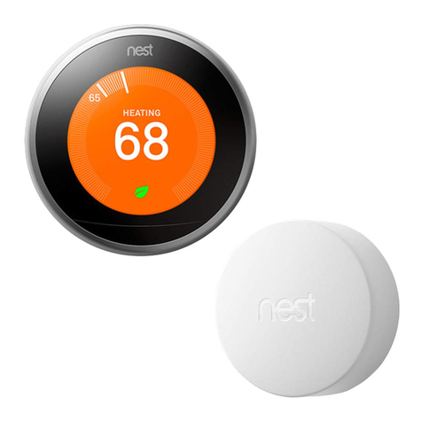
Technical specifications
Nest Learning Thermostat
2nd Generation
Nest Learning Thermostat
1st Generation
Sensors
Temperature sensor +/- .5°F
Humidity sensor +/- 3%RH
Near-field activity sensor
Far-field activity sensor
Ambient light sensor
Temperature sensor +/- .5°F
Humidity sensor +/- 3%RH
Near-field activity sensor
Far-field activity sensor
Ambient light sensor
Power
Power sharing
(with built-in rechargeable Li-ion battery, 7-10
year battery life)
No external power required
No common wire required with most
installations
Power sharing
(with built-in rechargeable Li-ion battery, 7-10
year battery life)
No external power required
No common wire required with most
installations
Display
24 bit color
320 x 320 pixel display
1.75" diameter
24 bit color
320 x 320 pixel display
1.75" diameter
Language
English
Spanish
French
English
Spanish
French
Nest Learning Thermostat installation & configuration guide Page 4

Nest Learning Thermostat
2nd Generation
Nest Learning Thermostat
1st Generation
Display
Mass = 215g / 7.6oz
Diameter = 83.0mm / 3.27”
Height = 28.0mm / 1.10”
Mass = 150g / 5.3oz
Diameter = 81.2mm / 3.20”
Height = 36.6mm / 1.44”
Base
Mass = 37g / 1.3oz
Diameter = 76.5mm / 3.01”
Height = 10.7mm / 0.42”
Mass = 48g / 1.7oz
Diameter = 74.1mm / 2.92”
Height = 15.5mm / 0.61”
Assembled
Mass = 215g / 7.6oz
Diameter = 83.0mm / 3.27”
Height = 32.0mm / 1.26”
Mass = 198g / 7.0oz
Diameter = 81.2mm / 3.20”
Height = 40.6mm / 1.60”
Green
RoHS compliant
Mercury free
100% recyclable packaging
RoHS compliant
Mercury free
100% recyclable packaging
Operation
Operating temp: 0°C to 40°C (32ºF to 104ºF)
Operating humidity: 0%RH to 90%RH
Storage temp: -20°C to 45°C (-4ºF to 113ºF )
Storage humidity: 40%RH to 80%RH
Operating temp: 0°C to 40°C (32ºF to 104ºF)
Operating humidity: 0%RH to 90%RH
Storage temp: -20°C to 45°C (-4ºF to 113ºF )
Storage humidity: 40%RH to 80%RH
Compressor
Lockout
2.5 minute minimum delay between
compressor cycles
2.5 minute minimum delay between
compressor cycles
Outdoor Temp
Sensors
Nest utilizes local weather data over Wi-Fi in
place of outdoor temperature sensors
Nest utilizes local weather data over Wi-Fi in
place of outdoor temperature sensors
Nest Learning Thermostat installation & configuration guide Page 5

Supported wiring
Nest Learning Thermostat 2nd Generation
Conventional connectors
Heat pump connectors
Y1
Stage 1 compressor relay
Y1
Stage 1 compressor relay
Y2
Stage 2 compressor relay
Y2
Stage 2 compressor relay
G
Fan relay
G
Fan relay
O/B
Not used
O/B
Changeover valve relay
Rc
24VAC power from cooling transformer*
Rc
Not used
W1
Stage 1 heat relay
W1
Stage 1 heat relay
W2/AUX
Stage 2 heat relay
W2/AUX
Auxiliary heat relay
C
24VAC common wire.
C
24VAC common wire.
*
Stage 3 heat (W3), humidification (HUM), or
dehumidification (DEHUM)
*
Emergency heat (E), humidification (HUM), or
dehumidification (DEHUM)
Rh
24VAC power from heating transformer*
Rh
24VAC power from transformer*
* No jumper wires required. You don’t need to hang on to any old jumper wires going from Rh (sometimes
just called R) to Rc. Nest will automatically jump these two connectors.
Nest Learning Thermostat installation & configuration guide Page 6

Nest Learning Thermostat 1st Generation
Conventional connectors
Heat pump connectors
Rh
24VAC power from heating transformer*
Rh
24VAC power from heating transformer*
W1
Stage 1 heat relay
W1
Not usually used
Y1
Stage 1 cooling compressor relay
Y1
Stage 1 compressor contact
G
Fan relay
G
Fan relay
C
24VAC common wire.
C
24VAC common wire.
O/B
Not used
O/B
Changeover valve
AUX/W2
Stage 2 heat relay
AUX/
W2
Auxiliary heat relay
Rc
24VAC power from cooling transformer*
Rc
24VAC power from cooling transformer*
* No jumper wires required. You don’t need to hang on to any old jumper wires going from Rh (sometimes
just called R) to Rc. Nest will automatically jump these two connectors.
Nest Learning Thermostat installation & configuration guide Page 7

Wiring diagrams:Conventional Systems
Conventional 1 stage heating
Label
Function
Y1
Compressor Relay (Stage 1)
Y2
Compressor Relay (Stage 2)
G
Fan Relay *
O/B
Heat Pump Changeover Valve
Rc
24VAC power from cooling transformer
W1
Heat Relay (Stage 1)
W2/AUX
Heat Relay (Stage 2)/Auxiliary Heat Relay
C
24VAC Common Wire †
*
Star connector: W3, E, HUM, or DHUM
Rh
24VAC power from heating transformer ‡
* Fan relay (G) is optional. However, without a G wire, Nest will not be able to control the fan independent of heating.
†Common wire (C) not required in most cases, but strongly recommended.
‡ Use Rh or Rc in single transformer systems; no jumper wire required. For dual transformer systems, use Rh for the heating
transformer and Rc for the cooling transformer.
Conventional 2 stage heating
Label
Function
Y1
Compressor Relay (Stage 1)
Y2
Compressor Relay (Stage 2)
G
Fan Relay *
O/B
Heat Pump Changeover Valve
Rc
24VAC power from cooling transformer
W1
Heat Relay (Stage 1)
W2/AUX
Heat Relay (Stage 2)/Auxiliary Heat Relay
C
24VAC Common Wire †
*
Star connector: W3, E, HUM, or DHUM
Rh
24VAC power from heating transformer ‡
* Fan relay (G) is optional. However, without a G wire, Nest will not be able to control the fan independent of heating.
†Common wire (C) not required in most cases, but strongly recommended.
‡ Use Rh or Rc in single transformer systems; no jumper wire required. For dual transformer systems, use Rh for the heating
transformer and Rc for the cooling transformer.
* Fan relay (G) is optional. However, without a G wire, Nest will not be able to control the fan independent of heating.
†Common wire (C) not required in most cases, but strongly recommended.
‡ Use Rh or Rc in single transformer systems; no jumper wire required. For dual transformer systems, use Rh for the heating
transformer and Rc for the cooling transformer.
* Fan relay (G) is optional. However, without a G wire, Nest will not be able to control the fan independent of heating.
†Common wire (C) not required in most cases, but strongly recommended.
‡ Use Rh or Rc in single transformer systems; no jumper wire required. For dual transformer systems, use Rh for the heating
transformer and Rc for the cooling transformer.
Nest Learning Thermostat installation & configuration guide Page 8

Conventional 3 stage heating
Label
Function
Y1
Compressor Relay (Stage 1)
Y2
Compressor Relay (Stage 2)
G
Fan Relay *
O/B
Heat Pump Changeover Valve
Rc
24VAC power from cooling transformer
W1
Heat Relay (Stage 1)
W2/AUX
Heat Relay (Stage 2)/Auxiliary Heat Relay
C
24VAC Common Wire †
*
Star connector: W3, E, HUM, or DHUM
Rh
24VAC power from heating transformer ‡
* Fan relay (G) is optional. However, without a G wire, Nest will not be able to control the fan independent of heating.
†Common wire (C) not required in most cases, but strongly recommended.
‡ Use Rh or Rc in single transformer systems; no jumper wire required. For dual transformer systems, use Rh for the heating
transformer and Rc for the cooling transformer.
* Fan relay (G) is optional. However, without a G wire, Nest will not be able to control the fan independent of heating.
†Common wire (C) not required in most cases, but strongly recommended.
‡ Use Rh or Rc in single transformer systems; no jumper wire required. For dual transformer systems, use Rh for the heating
transformer and Rc for the cooling transformer.
* Fan relay (G) is optional. However, without a G wire, Nest will not be able to control the fan independent of heating.
†Common wire (C) not required in most cases, but strongly recommended.
‡ Use Rh or Rc in single transformer systems; no jumper wire required. For dual transformer systems, use Rh for the heating
transformer and Rc for the cooling transformer.
Conventional 1 stage heating and 1 stage cooling
Label
Function
Y1
Compressor Relay (Stage 1)
Y2
Compressor Relay (Stage 2)
G
Fan Relay *
O/B
Heat Pump Changeover Valve
Rc
24VAC power from cooling transformer
W1
Heat Relay (Stage 1)
W2/AUX
Heat Relay (Stage 2)/Auxiliary Heat Relay
C
24VAC Common Wire †
*
Star connector: W3, E, HUM, or DHUM
Rh
24VAC power from heating transformer ‡
* Fan relay (G) is optional. However, without a G wire, Nest will not be able to control the fan independent of heating.
†Common wire (C) not required in most cases, but strongly recommended.
‡ Use Rh or Rc in single transformer systems; no jumper wire required. For dual transformer systems, use Rh for the heating
transformer and Rc for the cooling transformer.
* Fan relay (G) is optional. However, without a G wire, Nest will not be able to control the fan independent of heating.
†Common wire (C) not required in most cases, but strongly recommended.
‡ Use Rh or Rc in single transformer systems; no jumper wire required. For dual transformer systems, use Rh for the heating
transformer and Rc for the cooling transformer.
* Fan relay (G) is optional. However, without a G wire, Nest will not be able to control the fan independent of heating.
†Common wire (C) not required in most cases, but strongly recommended.
‡ Use Rh or Rc in single transformer systems; no jumper wire required. For dual transformer systems, use Rh for the heating
transformer and Rc for the cooling transformer.
Nest Learning Thermostat installation & configuration guide Page 9

Conventional 2 stage heating and 1 stage cooling
Label
Function
Y1
Compressor Relay (Stage 1)
Y2
Compressor Relay (Stage 2)
G
Fan Relay *
O/B
Heat Pump Changeover Valve
Rc
24VAC power from cooling transformer
W1
Heat Relay (Stage 1)
W2/AUX
Heat Relay (Stage 2)/Auxiliary Heat Relay
C
24VAC Common Wire †
*
Star connector: W3, E, HUM, or DHUM
Rh
24VAC power from heating transformer ‡
* Fan relay (G) is optional. However, without a G wire, Nest will not be able to control the fan independent of heating.
†Common wire (C) not required in most cases, but strongly recommended.
‡ Use Rh or Rc in single transformer systems; no jumper wire required. For dual transformer systems, use Rh for the heating
transformer and Rc for the cooling transformer.
* Fan relay (G) is optional. However, without a G wire, Nest will not be able to control the fan independent of heating.
†Common wire (C) not required in most cases, but strongly recommended.
‡ Use Rh or Rc in single transformer systems; no jumper wire required. For dual transformer systems, use Rh for the heating
transformer and Rc for the cooling transformer.
* Fan relay (G) is optional. However, without a G wire, Nest will not be able to control the fan independent of heating.
†Common wire (C) not required in most cases, but strongly recommended.
‡ Use Rh or Rc in single transformer systems; no jumper wire required. For dual transformer systems, use Rh for the heating
transformer and Rc for the cooling transformer.
Conventional 2 stage heating and 2 stage cooling
Label
Function
Y1
Compressor Relay (Stage 1)
Y2
Compressor Relay (Stage 2)
G
Fan Relay *
O/B
Heat Pump Changeover Valve
Rc
24VAC power from cooling transformer
W1
Heat Relay (Stage 1)
W2/AUX
Heat Relay (Stage 2)/Auxiliary Heat Relay
C
24VAC Common Wire †
*
Star connector: W3, E, HUM, or DHUM
Rh
24VAC power from heating transformer ‡
* Fan relay (G) is optional. However, without a G wire, Nest will not be able to control the fan independent of heating.
†Common wire (C) not required in most cases, but strongly recommended.
‡ Use Rh or Rc in single transformer systems; no jumper wire required. For dual transformer systems, use Rh for the heating
transformer and Rc for the cooling transformer.
* Fan relay (G) is optional. However, without a G wire, Nest will not be able to control the fan independent of heating.
†Common wire (C) not required in most cases, but strongly recommended.
‡ Use Rh or Rc in single transformer systems; no jumper wire required. For dual transformer systems, use Rh for the heating
transformer and Rc for the cooling transformer.
* Fan relay (G) is optional. However, without a G wire, Nest will not be able to control the fan independent of heating.
†Common wire (C) not required in most cases, but strongly recommended.
‡ Use Rh or Rc in single transformer systems; no jumper wire required. For dual transformer systems, use Rh for the heating
transformer and Rc for the cooling transformer.
Nest Learning Thermostat installation & configuration guide Page 10

Conventional 3 stage heating and 2 stage cooling
Label
Function
Y1
Compressor Relay (Stage 1)
Y2
Compressor Relay (Stage 2)
G
Fan Relay *
O/B
Heat Pump Changeover Valve
Rc
24VAC power from cooling transformer
W1
Heat Relay (Stage 1)
W2/AUX
Heat Relay (Stage 2)/Auxiliary Heat Relay
C
24VAC Common Wire †
*
Star connector: W3, E, HUM, or DHUM
Rh
24VAC power from heating transformer ‡
* Fan relay (G) is optional. However, without a G wire, Nest will not be able to control the fan independent of heating.
†Common wire (C) not required in most cases, but strongly recommended.
‡ Use Rh or Rc in single transformer systems; no jumper wire required. For dual transformer systems, use Rh for the heating
transformer and Rc for the cooling transformer.
* Fan relay (G) is optional. However, without a G wire, Nest will not be able to control the fan independent of heating.
†Common wire (C) not required in most cases, but strongly recommended.
‡ Use Rh or Rc in single transformer systems; no jumper wire required. For dual transformer systems, use Rh for the heating
transformer and Rc for the cooling transformer.
* Fan relay (G) is optional. However, without a G wire, Nest will not be able to control the fan independent of heating.
†Common wire (C) not required in most cases, but strongly recommended.
‡ Use Rh or Rc in single transformer systems; no jumper wire required. For dual transformer systems, use Rh for the heating
transformer and Rc for the cooling transformer.
Conventional 1 stage heating and 2 stage cooling
Label
Function
Y1
Compressor Relay (Stage 1)
Y2
Compressor Relay (Stage 2)
G
Fan Relay *
O/B
Heat Pump Changeover Valve
Rc
24VAC power from cooling transformer
W1
Heat Relay (Stage 1)
W2/AUX
Heat Relay (Stage 2)/Auxiliary Heat Relay
C
24VAC Common Wire †
*
Star connector: W3, E, HUM, or DHUM
Rh
24VAC power from heating transformer ‡
* Fan relay (G) is optional. However, without a G wire, Nest will not be able to control the fan independent of heating.
†Common wire (C) not required in most cases, but strongly recommended.
‡ Use Rh or Rc in single transformer systems; no jumper wire required. For dual transformer systems, use Rh for the heating
transformer and Rc for the cooling transformer.
* Fan relay (G) is optional. However, without a G wire, Nest will not be able to control the fan independent of heating.
†Common wire (C) not required in most cases, but strongly recommended.
‡ Use Rh or Rc in single transformer systems; no jumper wire required. For dual transformer systems, use Rh for the heating
transformer and Rc for the cooling transformer.
* Fan relay (G) is optional. However, without a G wire, Nest will not be able to control the fan independent of heating.
†Common wire (C) not required in most cases, but strongly recommended.
‡ Use Rh or Rc in single transformer systems; no jumper wire required. For dual transformer systems, use Rh for the heating
transformer and Rc for the cooling transformer.
Nest Learning Thermostat installation & configuration guide Page 11

Wiring diagrams:Heat Pump Systems
1 stage heat pump
1 stage heat pump
1 stage heat pump
Label
Function
Y1
Compressor Relay (Stage 1)
Y2
Compressor Relay (Stage 2)
G
Fan Relay *
O/B
Heat Pump Changeover Valve
Rc
24VAC power from cooling transformer
W1
Heat Relay (Stage 1)
W2/AUX
Heat Relay (Stage 2)/Auxiliary Heat Relay
C
24VAC Common Wire †
*
Star connector: W3, E, HUM, or DHUM
Rh
24VAC power from heating transformer ‡
* Fan relay (G) is optional. However, without a G wire, Nest will not be able to control the fan independent of heating.
†Common wire (C) not required in most cases, but strongly recommended.
‡ Use Rh or Rc in single transformer systems; no jumper wire required. For dual transformer systems, use Rh for the heating
transformer and Rc for the cooling transformer.
* Fan relay (G) is optional. However, without a G wire, Nest will not be able to control the fan independent of heating.
†Common wire (C) not required in most cases, but strongly recommended.
‡ Use Rh or Rc in single transformer systems; no jumper wire required. For dual transformer systems, use Rh for the heating
transformer and Rc for the cooling transformer.
* Fan relay (G) is optional. However, without a G wire, Nest will not be able to control the fan independent of heating.
†Common wire (C) not required in most cases, but strongly recommended.
‡ Use Rh or Rc in single transformer systems; no jumper wire required. For dual transformer systems, use Rh for the heating
transformer and Rc for the cooling transformer.
1 stage heat pump with aux heat
Label
Function
Y1
Compressor Relay (Stage 1)
Y2
Compressor Relay (Stage 2)
G
Fan Relay *
O/B
Heat Pump Changeover Valve
Rc
24VAC power from cooling transformer
W1
Heat Relay (Stage 1)
W2/AUX
Heat Relay (Stage 2)/Auxiliary Heat Relay
C
24VAC Common Wire †
*
Star connector: W3, E, HUM, or DHUM
Rh
24VAC power from heating transformer ‡
* Fan relay (G) is optional. However, without a G wire, Nest will not be able to control the fan independent of heating.
†Common wire (C) not required in most cases, but strongly recommended.
‡ Use Rh or Rc in single transformer systems; no jumper wire required. For dual transformer systems, use Rh for the heating
transformer and Rc for the cooling transformer.
* Fan relay (G) is optional. However, without a G wire, Nest will not be able to control the fan independent of heating.
†Common wire (C) not required in most cases, but strongly recommended.
‡ Use Rh or Rc in single transformer systems; no jumper wire required. For dual transformer systems, use Rh for the heating
transformer and Rc for the cooling transformer.
* Fan relay (G) is optional. However, without a G wire, Nest will not be able to control the fan independent of heating.
†Common wire (C) not required in most cases, but strongly recommended.
‡ Use Rh or Rc in single transformer systems; no jumper wire required. For dual transformer systems, use Rh for the heating
transformer and Rc for the cooling transformer.
Nest Learning Thermostat installation & configuration guide Page 12

1 stage heat pump with aux heat and emergency heat
Label
Function
Y1
Compressor Relay (Stage 1)
Y2
Compressor Relay (Stage 2)
G
Fan Relay *
O/B
Heat Pump Changeover Valve
Rc
24VAC power from cooling transformer
W1
Heat Relay (Stage 1)
W2/AUX
Heat Relay (Stage 2)/Auxiliary Heat Relay
C
24VAC Common Wire †
*
Star connector: W3, E, HUM, or DHUM
Rh
24VAC power from heating transformer ‡
* Fan relay (G) is optional. However, without a G wire, Nest will not be able to control the fan independent of heating.
†Common wire (C) not required in most cases, but strongly recommended.
‡ Use Rh or Rc in single transformer systems; no jumper wire required. For dual transformer systems, use Rh for the heating
transformer and Rc for the cooling transformer.
* Fan relay (G) is optional. However, without a G wire, Nest will not be able to control the fan independent of heating.
†Common wire (C) not required in most cases, but strongly recommended.
‡ Use Rh or Rc in single transformer systems; no jumper wire required. For dual transformer systems, use Rh for the heating
transformer and Rc for the cooling transformer.
* Fan relay (G) is optional. However, without a G wire, Nest will not be able to control the fan independent of heating.
†Common wire (C) not required in most cases, but strongly recommended.
‡ Use Rh or Rc in single transformer systems; no jumper wire required. For dual transformer systems, use Rh for the heating
transformer and Rc for the cooling transformer.
2 stage heat pump
2 stage heat pump
2 stage heat pump
Label
Function
Y1
Compressor Relay (Stage 1)
Y2
Compressor Relay (Stage 2)
G
Fan Relay *
O/B
Heat Pump Changeover Valve
Rc
24VAC power from cooling transformer
W1
Heat Relay (Stage 1)
W2/AUX
Heat Relay (Stage 2)/Auxiliary Heat Relay
C
24VAC Common Wire †
*
Star connector: W3, E, HUM, or DHUM
Rh
24VAC power from heating transformer ‡
* Fan relay (G) is optional. However, without a G wire, Nest will not be able to control the fan independent of heating.
†Common wire (C) not required in most cases, but strongly recommended.
‡ Use Rh or Rc in single transformer systems; no jumper wire required. For dual transformer systems, use Rh for the heating
transformer and Rc for the cooling transformer.
* Fan relay (G) is optional. However, without a G wire, Nest will not be able to control the fan independent of heating.
†Common wire (C) not required in most cases, but strongly recommended.
‡ Use Rh or Rc in single transformer systems; no jumper wire required. For dual transformer systems, use Rh for the heating
transformer and Rc for the cooling transformer.
* Fan relay (G) is optional. However, without a G wire, Nest will not be able to control the fan independent of heating.
†Common wire (C) not required in most cases, but strongly recommended.
‡ Use Rh or Rc in single transformer systems; no jumper wire required. For dual transformer systems, use Rh for the heating
transformer and Rc for the cooling transformer.
Nest Learning Thermostat installation & configuration guide Page 13

2 stage heat pump with aux heat
Label
Function
Y1
Compressor Relay (Stage 1)
Y2
Compressor Relay (Stage 2)
G
Fan Relay *
O/B
Heat Pump Changeover Valve
Rc
24VAC power from cooling transformer
W1
Heat Relay (Stage 1)
W2/AUX
Heat Relay (Stage 2)/Auxiliary Heat Relay
C
24VAC Common Wire †
*
Star connector: W3, E, HUM, or DHUM
Rh
24VAC power from heating transformer ‡
* Fan relay (G) is optional. However, without a G wire, Nest will not be able to control the fan independent of heating.
†Common wire (C) not required in most cases, but strongly recommended.
‡ Use Rh or Rc in single transformer systems; no jumper wire required. For dual transformer systems, use Rh for the heating
transformer and Rc for the cooling transformer.
* Fan relay (G) is optional. However, without a G wire, Nest will not be able to control the fan independent of heating.
†Common wire (C) not required in most cases, but strongly recommended.
‡ Use Rh or Rc in single transformer systems; no jumper wire required. For dual transformer systems, use Rh for the heating
transformer and Rc for the cooling transformer.
* Fan relay (G) is optional. However, without a G wire, Nest will not be able to control the fan independent of heating.
†Common wire (C) not required in most cases, but strongly recommended.
‡ Use Rh or Rc in single transformer systems; no jumper wire required. For dual transformer systems, use Rh for the heating
transformer and Rc for the cooling transformer.
2 stage heat pump with aux heat and emergency heat
Label
Function
Y1
Compressor Relay (Stage 1)
Y2
Compressor Relay (Stage 2)
G
Fan Relay *
O/B
Heat Pump Changeover Valve
Rc
24VAC power from cooling transformer
W1
Heat Relay (Stage 1)
W2/AUX
Heat Relay (Stage 2)/Auxiliary Heat Relay
C
24VAC Common Wire †
*
Star connector: W3, E, HUM, or DHUM
Rh
24VAC power from heating transformer ‡
* Fan relay (G) is optional. However, without a G wire, Nest will not be able to control the fan independent of heating.
†Common wire (C) not required in most cases, but strongly recommended.
‡ Use Rh or Rc in single transformer systems; no jumper wire required. For dual transformer systems, use Rh for the heating
transformer and Rc for the cooling transformer.
* Fan relay (G) is optional. However, without a G wire, Nest will not be able to control the fan independent of heating.
†Common wire (C) not required in most cases, but strongly recommended.
‡ Use Rh or Rc in single transformer systems; no jumper wire required. For dual transformer systems, use Rh for the heating
transformer and Rc for the cooling transformer.
* Fan relay (G) is optional. However, without a G wire, Nest will not be able to control the fan independent of heating.
†Common wire (C) not required in most cases, but strongly recommended.
‡ Use Rh or Rc in single transformer systems; no jumper wire required. For dual transformer systems, use Rh for the heating
transformer and Rc for the cooling transformer.
Nest Learning Thermostat installation & configuration guide Page 14

Wiring diagrams:Humidifiers and Dehumidifiers
The 2nd generation Nest LearningThermostat is compatible with most whole home humidifier and
dehumidifier systems that connect to your thermostat with one or two low voltage wires.
Compatible wires have one of the following labels:
•H, Hum, Hum1, H2, Hum2
•D, DH, Dhum, Dehum, D2, DH2, Dhum2, Dehum2
Regardless of whether your system has one wire or two, you will need to figure out if the humidifier or
dehumidifier can be activated on its own or if it requires heating or cooling to be activated at the same
time. You’ll also need to determine other settings, such as whether the fan is required during operation.
Nest's * (STAR) terminal is a powered terminal. If connecting to a humidifier/dehumidifier that requires
connection to unpowered terminals, add a 24VAC relay suitable for HVAC equipment use. Consult
humidifier/dehumidifier installation manual for wiring requirements.
Important Note:In dual transformer set ups (where there is both an Rh and an Rc wire connected to Nest),
Nest will power the * connector from the Rh wire.
Label
Function
Y1
Compressor Relay (Stage 1)
Y2
Compressor Relay (Stage 2)
G
Fan Relay *
O/B
Heat Pump Changeover
Valve
Rc
24VAC power from cooling
transformer
W1
Heat Relay (Stage 1)
W2/AUX
Heat Relay (Stage 2)/
Auxiliary Heat Relay
C
24VAC Common Wire †
*
Star connector: W3, E, HUM,
or DHUM
Rh
24VAC power from heating
transformer ‡
Nest Learning Thermostat installation & configuration guide Page 15

Possible configurations:
Stand Alone Humidifier, 1 Wire
•This system has a humidifier that is separate from the HVAC system.
•Install the hum wire directly into the * terminal at Nest.
•Correctly ground the other wire from the Humidifier.
•No relay is recommended.
Stand Alone Humidifier, 2 Wire
•This system has a humidifier that is separate from the HVAC system.
•Install the 2 hum wires directly into the relay.
•Run the single wire from the relay to the * terminal at Nest.
•Nest recommends the White Rogers 90-290Q or similar 24VAC HVAC relay.
Nest Learning Thermostat installation & configuration guide Page 16

Built-in Humidifier System, 2 Wire
•This system has a humidifier built in to its HVAC system and 2 separate hum wires.
•Install the 2 hum wires directly into the relay
•Run the single wire from the relay to the * terminal at Nest.
•Nest recommends the White Rogers 90-290Q or similar 24VAC HVAC relay.
Built-in Humidifier System, 1 Wire
•This system has a humidifier built in to its HVAC system and only 1 hum wire.
•Connect the hum wire from the built-in system directly to the * terminal at the Nest.
•No relay is recommended.
Nest Learning Thermostat installation & configuration guide Page 17

Configuring Nest with Pro Setup
Pro Setup lets installation professionals quickly configure the way Nest controls an HVAC system. Complex
systems such as dual fuel systems, humidifiers and dehumidifiers require Pro Setup. Nest recommends
professional installation to homeowners with these systems. Pro Setup can be used the first time you set
up Nest or anytime through the SETTINGS menu.
What is Pro Setup?
Pro Setup allows HVAC technicians to configure how Nest controls your system. Pro Setup can configure
both simple and complex systems. However, some configuration options are only available using Pro Setup.
During setup, Nest will ask if you are a professional installer and allow pros to bypass the standard setup
interview for the homeowner. Pro Setup can also be accessed in the EQUIPMENT section of SETTINGS at
any time.
If Pro Setup is configured incorrectly it could cause problems with your HVAC system. Therefore, Nest
strongly advises that only trained installation professionals use Pro Setup.
How do I enter Pro Setup?
During setup on a Nest Learning Thermostat, you’ll be asked if you’re a homeowner or a professional. If you
answer “professional,” you’ll receive Pro Setup options.
To enter Pro Setup on the Nest Learning Thermostat after initial setup:
•Go to SETTINGS > EQUIPMENT > CONTINUE > CONTINUE > PRO SETUP
Read the disclaimer. Only continue if you’re an HVAC professional.
How do I use Pro Setup?
Pro Setup gives you the ability to identify and configure how Nest should
control each wire you connect to the Nest base.
When you first enter Pro Setup, you’ll see an image of the Nest
connectors. Connectors with wires attached will be be
highlighted in green or yellow. Green indicates that the wire has
only one default setting. The Rc, Rh, C, and G connectors are
examples. Yellow indicates connectors with multiple options.
Nest selects default settings for these connectors, but you’ll
want to verify and/or modify these settings to make sure Nest
is controlling each wire appropriately.
To configure a wire, just turn the ring to highlight each connector
and press to select it.
Each wire will show Type, which describes the function of that wire. In
most cases the Type cannot be modified - it’s dictated by the wiring
configuration and by whether or not the system is dual fuel. The Type for the * connector is always
customizable.
Connectors that control a heating or cooling function will also have a Source setting (to identify the type of
fuel used to heat or cool) and a Delivery setting (to describe how heating or cooling is distributed
Nest Learning Thermostat installation & configuration guide Page 18
Other manuals for Learning thermostat
7
Table of contents
Other nest Thermostat manuals

nest
nest Learning thermostat User manual

nest
nest Learning thermostat User manual

nest
nest Learning User manual

nest
nest Learning thermostat User manual

nest
nest Learning thermostat User manual

nest
nest Thermostat E User manual

nest
nest T3007ES Operating and safety instructions

nest
nest Thermostat User manual

nest
nest Thermostat E User manual

nest
nest Learning Thermostat D3 User manual