Net Safety TL-UV/IR-Kit User manual

UV/IR Test Lamp Kit
User Manual
Model: TL-UV/IR-Kit
Part Number: MAN-0033 Rev 02
October 2008

MAN-0033 Rev 02 TL-UV/IR- Kit
October 2008 2
IMPORTANT INFORMATION
This manual is for informational purposes only. Although every effort has been made to ensure the
correctness of the information, technical inaccuracies may occur and periodic changes may be made
without notice. Net Safety Monitoring Inc., assumes no responsibility for any error contained within this
manual.
This manual is a guide for use of a Test Lamp and the data and procedures contained within this
document have been verified and are believed to be adequate for the intended use of the Test Lamp. If the
Test Lamp or procedures are used for purposes other than as described in the manual without receiving
prior confirmation of validity or suitability, Net Safety Monitoring Inc. does not guarantee the results and
assumes no obligation or liability.
No part of this manual may be copied, disseminated or distributed without the express consent of Net
Safety Monitoring Inc.
Net Safety Monitoring Inc. products are carefully designed and manufactured from high quality
components and can be expected to provide many years of trouble free service. Each product is
thoroughly tested, inspected and calibrated prior to shipment. Failures can occur which are beyond the
control of the manufacturer. Failures can be minimized by adhering to the operating and maintenance
instructions herein. Where the absolute greatest of reliability is required, redundancy should be designed
into the system.
WARRANTY
Net Safety Monitoring Inc warrants this product against defective parts and workmanship for a period of
for 24 months from date of purchase. No other warranties or liability, expressed or implied, will be
honoured by Net Safety Monitoring Inc.
Contact Net Safety Monitoring Inc. or an authorized representative for details.
We welcome your input at Net Safety Monitoring Inc. If you have any comments please contact us at the
telephone number or address below or visit our web-site, www.net-safety.com, and complete our on-line
customer survey.
CONTACT INFORMATION
Net Safety Monitoring Inc Direct: (403) 219-0688
Corporate Headquarters Facsimile: (403) 219-0694
Calgary, AB Canada T1Y 7J7 Web-site: www.net-safety.com

MAN-0033 Rev 02 TL-UV/IR- Kit
October 2008 3
TableofContents
SECTION1:UV/IRTestLampkit(TL‐UV/IR‐Kit)...........................................................................................4
1.1TheUV/IRTestLamp(TL‐UV/IR‐EX)...................................................................................................4
Figure 1: UV/IR Test Lamp.................................................................................................................4
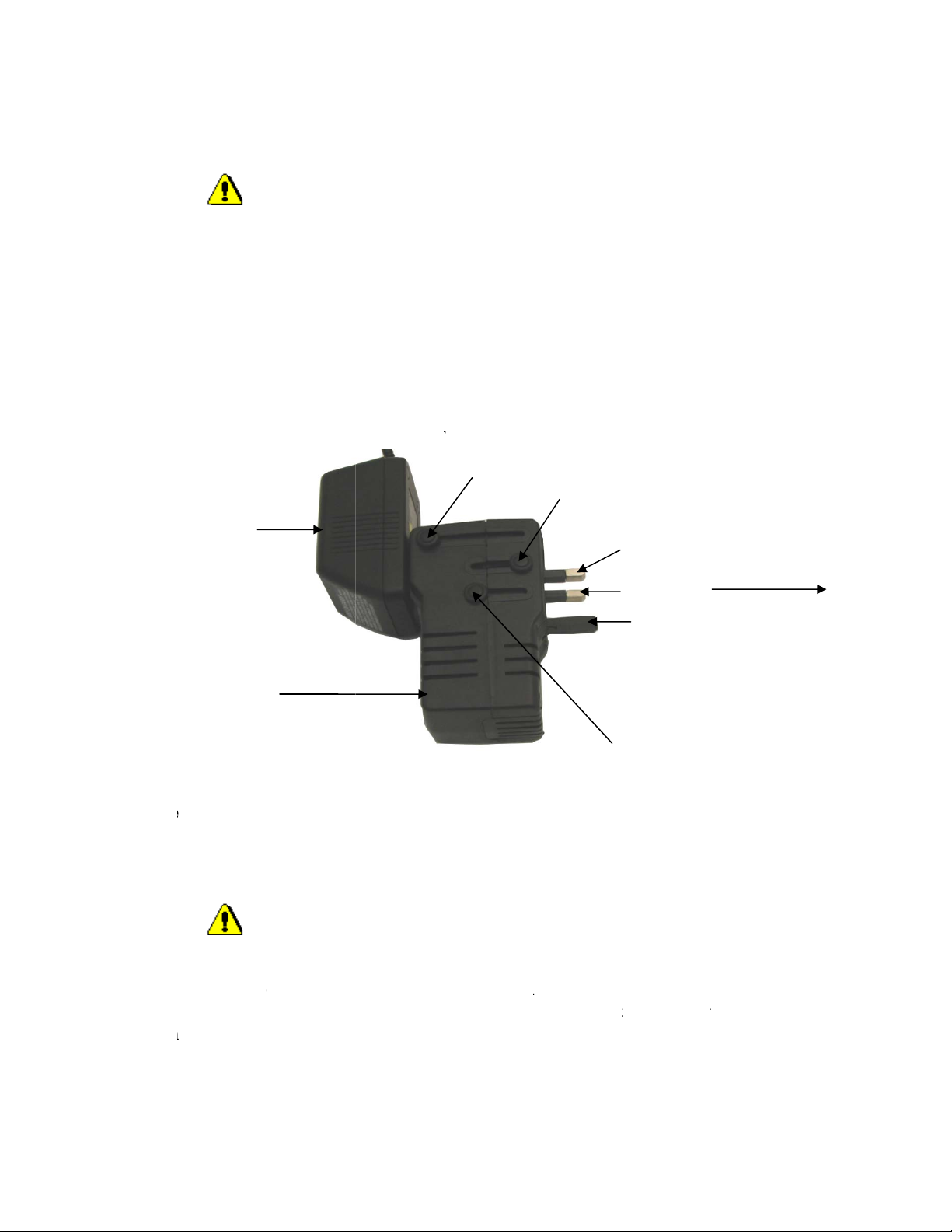
1.2BatteryChargerwith50WattForeignTravelVoltageConverter.....................................................5
Figure 2: Battery Charger with Voltage Converter...............................................................................5
1.3BatteryPack......................................................................................................................................5
SECTION2:OPERATINGINSTRUCTIONS.......................................................................................................6
2.1BasicResponseTest..........................................................................................................................6
2.2SystemResponseTest.......................................................................................................................6
2.3Troubleshoot.....................................................................................................................................6
2.4SpareParts/Accessories..................................................................................................................6
2.5HowtoReturnEquipment...............................................................................................................7
Appendix.......................................................................................................................................................8
AppendixA:ElectrostaticSensitiveDevice(ESD).........................................................................................8
AppendixB:Specifications............................................................................................................................9
MAN-0033 Rev 02 TL-UV/IR- Kit
October 2008 4
SECTION 1: UV/IR Test Lamp kit (TL-UV/IR -Kit)
Warning: The light emitted by the Test Lamp can be very harmful to the eyes. Avoid looking
directly at the beam when operating.
Contents of the UV/IR Test Lamp kit (TL-UV/IR -Kit)
1. UV/IRS Test Lamp.
2. 50 Watt Foreign Travel Voltage Converter.
3. Battery Charger.
4. Two 9.6 Volt (dc) battery pack (one of which is a spare).
5. Window Cleaning Kit (cloth and cleaning solution).
6. Test Lamp manual.
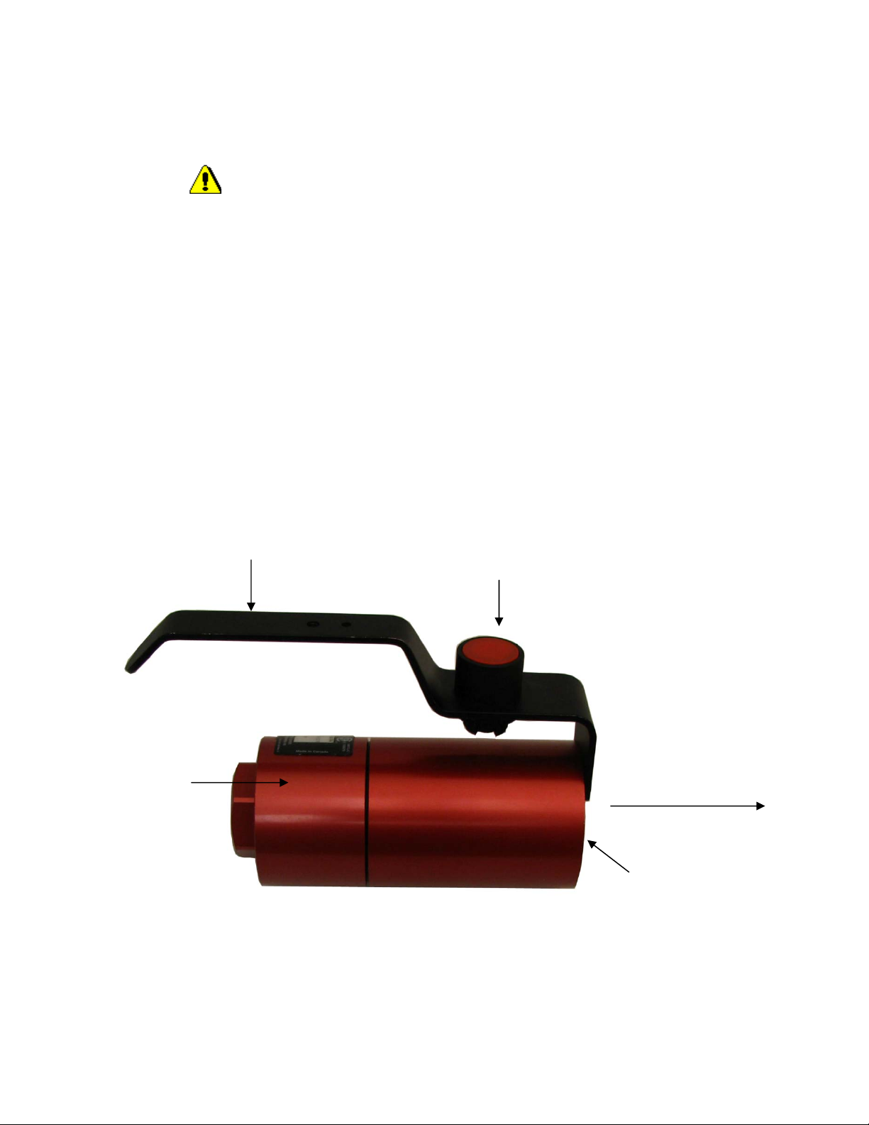
1.1TheUV/IRTestLamp(TLUV/IREX)
Figure 1: UV/IR Test Lamp
Magnetic Push
Button Switch
Handle
Test Lamp Housing
Assembly
Front of unit
with lens
Path of directed
beam
MAN-00
3
October
2
1.2Ba
Warni
n
The Volt
a
blades to
dependin
g
selectabl
e
country.
P
the 110/1
2
plug the
c
approxim
Figure 2
Note: B
e
1.3Ba
Warni
n
A 9.6 Vd
c
available
)
the inclu
d
long as t
h
Batt
e
Volt
a
3
3 Rev 02 T
L
2
008
tteryCha
r
ng
:
D
o
a
ge Converte
r
operate with
g
on the cou
n
e
switch (A,
B
P
osition B (3
2
0 Volts AC
c
harger -conv
ately 16 hou
r
: Battery Ch
a
e
sure to disc
o
tteryPac
k
ng
:
Do
c
battery pac
k
)
. The includ
e
d
ed charger.
T
h
ey will powe
e
ryCharger
a
geConverte
r
L
-UV/IR- Kit
r
gerwith
5
o
not plug th
e
r
is flexible t
o
110 or 120
V
n
try. This ad
a
B
or C) into p
o
pins) is curr
e
outlet on the
erter assem
bl
r
s per battery
a
rger with V
o
o
nnect the ch
a
k
not open the
k
is required
a
e
d battery pa
c
T
o maintain t
h
r up the lam
p
r
5
0WattF
o
e
Voltage Co
n
o
allow use i
n
V
olts AC. Dif
f
a
pter convert
s
o
sition to get
e
ntly selected
.
converter.
C
l
y into a 220/
2
pack.
o
ltage Conve
r
a
rger -conver
t
Test Lamp
h
a
nd this is lo
c
c
ks are recha
r
h
e batteries i
n
p
properly be
f
o
reignTr
a
n
verter into a
n
various cou
n
f
erent AC ou
t
s
220/240 Vo
l
the desired
p
.
See Figure
2
C
onnect the b
a
2
40 Volts A
C
r
ter.
t
er assembly
h
ousing or us
e
c
ated inside t
h
r
geable NiC
a
n
optimum w
o
f
ore being re
c
A
a
velVolta
g
DC voltage
s
n
tries. The U
S
t
le
t
arrangem
e
l
ts AC to 11
0
p
in configura
t
2
. The batter
y
a
ttery pack to
C
mains. The
fro
m
the AC
e
the charger
h
e uni
t
(one s
p
a
d types and t
h
o
rking condi
t
c
harged.
B
C
g
eConve
r
s
ystem.
S
A and Cana
d
e
nts can be f
a
0
/120 Volts
A
t
ion for a par
t
y
charger is t
h
the battery c
h
charging ti
m
mains outlet
in a Hazardo
u
p
are battery
p
h
ese may be
r
t
ion, they sho
u
C
Pin1
Pin2
Pin3
r
ter
d
a use two fl
a
a
cilitated,
A
C. Slide the
t
icular locati
o
h
en plugged i
n
h
arger lead a
n
m
e is
when not in
u
u
s area.
p
ack is also
r
echarged us
i
u
ld be used a
To AC main
s
a
t
o
n or
n
to
n
d
u
se.
i
ng
s
s
5

MAN-0033 Rev 02 TL-UV/IR- Kit
October 2008 6
SECTION 2: OPERATING INSTRUCTIONS
2.1BasicResponseTest
It is recommended that two persons perform the testing procedure. One should operate the Test Lamp,
while the other set up the controllers and or Fire Detector to observe the response of the system to the
Test Lamp.
The first step in testing a UV/IR system is to place the controller in bypass mode. Activate the Test Lamp
by pressing the magnetic push button switch and direct the centre of the beam to the window of the
detector from a distance not greater than five feet. Observe the current output and/ or changing of state of
the controller relay. When the Fire Detector fully detects the beam from the Test Lamp a current output
20 mA will be observed and the state of the controller’s alarm relay will change.
If using a UV/IR stand alone detector, measure the current output and observe the Red LED. Monitor
changes in the state of unit’s alarm relay, if a relayed unit is being used. When the Fire Detector fully
detects the beam from the Test Lamp, a current output of 20 mA will be seen for Analog units and the
state of the alarm relay will change for Relayed units. The Red LED will flash to indicate the simulated
fire.
If the above test does not produce desired results (20 mA output current or change in the state of the
Alarm relay), there may be a problem with the wiring or the battery pack inside the Test Lamp enclosure
may be depleted. Clean all optical surfaces, recharge the battery if necessary and repeat the test. Contact
the manufacturer immediately, if the Fire Detector still does not respond.
2.2SystemResponseTest
It is important to verify system response to a fire. System response includes relay and analog output
activation. This test is performed with the controller on-line, therefore it is important to disable all
external response devices and shut-downs. Utilize the Test Lamp as described above and verify that the
controller outputs become active as programmed. Carefully verify analog output response and relay
response. Remember to enable the external response devices after the test.
2.3Troubleshoot
The Test Lamp is not designed to be repaired in the field. If the detector does not respond to the Test
Lamp as described, check the batteries and charge or replace as necessary. If the problem persists please
contact our service department to try and resolve the issue over the phone. If the issue cannot be solved
over the phone, the Test Lamp may have to be returned to the factory for repair. Refer to “How to Return
Equipment”.
2.4SpareParts/Accessories
Net Safety Description
TL-UV/IR-EX Class 1, Division 1, UV/IR Test Lamp
TLS-004-00-EU Charger Assembly with 50 Watt Voltage Converter
(European)
TLS-004-00 Battery Charger(N. American)
BAT-0004 Battery pack

MAN-0033 Rev 02 TL-UV/IR- Kit
October 2008 7
2.5HowtoReturnEquipment
A Material Return Authorization number is required in order to return equipment. Please contact Net
Safety Monitoring at (403) 219-0688, before returning equipment or consult our Service Department to
possibly avoid returning equipment.
If you are required to return equipment, include the following information:
1. A Material Return Authorization number (provided over the phone to you by Net Safety).
2. A detailed description of the problem. The more specific you are regarding the problem, the
quicker our Service Department can determine and correct the problem.
3. A company name, contact name and telephone number.
4. A purchase order, from your company, authorizing repairs or request for quote.
5. Ship all equipment, prepaid to: Net Safety Monitoring Inc.,
2721 Hopewell Place NE,
Calgary, Alberta, Canada, T1Y 7J7
6. Mark all packages: RETURN for REPAIR.
7. Waybills, for shipment outside Canada, must state: Equipment being returned for repair
All charges to be billed to the sender
Ensure a duplicate copy of the packing slip is enclosed inside the box indicating item 1 – 4 along with the
courier and account number for returning the goods.
Pack items to protect them from damage and use anti-static bags or aluminum-backed cardboard as
protection from electro-static discharge.
ALL equipment must be shipped prepaid. Collect shipments will not be accepted.

MAN-0033 Rev 02 TL-UV/IR- Kit
October 2008 8
Appendix
Appendix A: Electrostatic Sensitive Device (ESD)
Definition: Electrostatic discharge (ESD) is the transfer, between bodies, of an electrostatic charge
caused by direct contact or induced by an electrostatic field.
The most common cause of ESD is physical contact. Touching an object can cause a discharge of
electrostatic energy—ESD! If the charge is sufficient and occurs near electronic components, it can
damage or destroy those components. In some cases, damage is instantaneous and an immediate
malfunction occurs. However, symptoms are not always immediate—performance may be marginal or
seemingly normal for an indefinite period of time, followed by a sudden failure.
To eliminate potential ESD damage, review the following guidelines:
•Handle boards by metal shields—taking care not to touch electronic components.
•Wear grounded wrist or foot straps, ESD shoes or heel grounders to dissipate unwanted static
energy.
•Prior to handling boards, dispel any charge in your body or equipment.
•Ensure all components are transported and stored in static safe packaging
•When returning boards, carefully package in the original carton and static protective wrapping
•Ensure ALL personnel are educated and trained in ESD Control Procedures
In general, exercise accepted and proven precautions normally observed when handling electrostatic
sensitive devices. A warning label is placed on the packaging, identifying product using electrostatic
sensitive semiconductor devices.

MAN-00
3
October
2
App
e
Specificat
i
Approvals
3
3 Rev 02 T
L
2
008
e
ndix B
i
on
Enclosure
Approvals
L
-UV/IR- Kit
: Speci
f
CSA
a
Te
m
f
ication
s
a
nd NRTL/C c
e
m
perature Co
d
s
UV/IR Tes
t
e
rtified for ha
z
d
e T6. Ex d II
B
t
Lamp (TL-
U
Type 4x
z
ardous locatio
B
+ H2 T6 (Cl
a
U
V/IR-EX)
ns. Class 1, D
i
a
ss 1, Zone 1
G
i
vision 1,Grou
p
G
roups IIB + H
p
s B,C and D.
2 T6).
9

NetSafetyMonitoringInc.
2721HopewellPlaceNE,Calgary,ABCanadaT1Y7J7
1‐866‐FIREGAS(347‐3427)|ph.(403)219‐0688|fx.(403)219‐0694
http://www.net‐safety.com|Email:nsmsales@net‐safety.com
PRODUCTSERVICESCONTACTINFORMATION
Telephone[8am‐5pmMDT]:(403)769‐6074|(403)717‐8219
Fax:(403)219‐0694Email:productservices@net‐safety.com
http://www.net‐safety.com/service/product_services.html
Table of contents
Other Net Safety Test Equipment manuals


