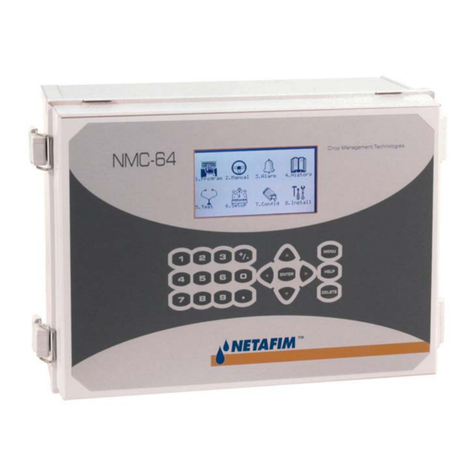
Netafim NLC-100SH Programming manual

NLC‐100SHInstallationandtroubleshooting
1
INSTALLATION & TROUBLESHOOTING MANUAL
NLC-100SH
NETAFIM LANDSCAPE CONTROLLERS
NLC-100SH

NLC‐100SHInstallationandtroubleshooting
2
CopyrightJanuary2014.Allrightsreserved.Nopartofthispublicationmay
bereproduced,storedinaretrievalsystem,ortransmittedinanyformor
byanymeanselectronic,mechanical,photocopying,recordingor
otherwisewithoutthepriorpermissionofthepublisher.
NetafimUSA
5470E.HomeAve.
Fresno,CA93727
Phone: (888)638‐2346
(559)453‐6800
Fax:(559)453‐6803
Email: [email protected]
450-230-0006/A

NLC‐100SHInstallationandtroubleshooting
3
TableofContents
Chapter1:IntroducingNLC‐100SH .......................................................................................... 7
TheTwo‐wireTechnology................................................................................ 7
Two‐wirelayout:..................................................................................7
Conventionallayout:...........................................................................8
TheController.......................................................................................... 8
IrrigationFeatures.................................................................................... 9
Chapter2:SystemInstallation ............................................................................................... 11
MountingtheController............................................................................... 11
Markingupthemountingholes............................................................. 12
ConnectingtheController............................................................................. 14
GroundingtheController....................................................................... 14
Connectingtheconventionalfieldwires....................................................... 15
ConnectingTwo‐wirewithsharedCommon.................................................. 16
ConnectingpureTwo‐wire............................................................................ 17
ConnectingMastervalveandFlowsensorviaTwo‐wire............................... 18
Programmingofdecodersandmastervalve................................................. 19
Fordecoders.......................................................................................... 20
Formastervalve..................................................................................... 20
ConnectingSensors....................................................................................... 21
ConnectinganETDevice............................................................................... 21
UsingaConnectedDevice(WeatherStation)................................................ 22
ConfiguringETInput............................................................................... 22
CheckingtheCurrentAggregatedETandRain.............................................. 30
ReadingcurrentaggregatedETandRainfigures..................................... 30
ConnectingaRainSensor.............................................................................. 33
ConfiguringforaRainSensor................................................................. 35
SettingHourlyMaximumRainandRainAlarmLevel..................................... 39

NLC‐100SHInstallationandtroubleshooting
4
SettingtheHourlyMax.RainandRainAlarmLevel................................ 40
ConnectingaFlowSensor............................................................................. 44
EnablingFlowSensorInput(pulses).............................................................. 45
EnablingflowsensorpulseinputintheNLC........................................... 45
ConfiguringforFlowSensorInput................................................................. 46
SelectingSensorType............................................................................. 47
Usingabuilt‐incalibrationprofile.......................................................... 47
SettingtheFlowSensorAdjustment....................................................... 51
Adjustingtheflowsensorinput.............................................................. 51
ViewingtheCurrentFlow............................................................................. 52
ConnectinganAlarm..................................................................................... 54
ConnectingaMoisturesensor...................................................................... 55
Connecting,ConfiguringandUsingMoistureSensors................................... 55
Connectingandconfiguringamoisturesensor....................................... 56
AssigninganIDtoasoilmoisturesensor............................................... 56
Configuringasoilmoisturesensor......................................................... 60
Chapter3:Systemactivation ................................................................................................. 63
Stationlicense........................................................................................ 63
Moisturelicense..................................................................................... 65
Chapter4:Troubleshootingconventionalvalvesfromthe
Controller ....................................................................................................................................... 67
TestingStations............................................................................................. 67
Enablingcurrentreadings....................................................................... 67
Runningthe"ElectricalTest".................................................................. 69
Specialcurrentreadingsfromthestationtest..................................71
Runningthe"WaterTest " .............................................................................. 72
Runningthetestprogram....................................................................... 72
TestingPrograms........................................................................................... 74
Chapter5:Troubleshooting3Ddecodersandvalves ............................................................ 75
NLC‐100SHInstallationandtroubleshooting
5
Testrun......................................................................................................... 75
DIPswitches.................................................................................................. 76
LEDNumberpatterns.................................................................................... 76
Act/ErrLEDcodes......................................................................................... 77
Glossary............................................................................................................. 79

NLC‐100SHInstallationandtroubleshooting
6

NLC‐100SHInstallationandtroubleshooting
7
Chapter1:IntroducingNLC‐100SH
TheNLCisamicroprocessorbasedirrigationcontrolsystem.Acentral
controllerandupto100fieldstationscompriseacompletesystem.In
additionthecontrollerwillacceptinputfromseveralexternalsensorsin
ordertoadjustitsirrigationtothelocalweatherconditions.
TheNLCcontrolsupto100solenoidsattachedtovalvesorrelaysviathe
built‐inconnectionboardandthreeexpansionboards.
Inadditioncommunicationbetweenthecontroller’s3Dandthestations
happensoveratwo‐wirepath.Dependingonthesignalfromthe
controller’s3D,thestationseachactivateordeactivateavalve.The
controller’s3Dsignalstothestationsbasedonconfigurableschedules,
eliminatingtheneedforhumaninteractionwhenthepark,gardenorother
surroundingsneedwatering‐oncesetup,theNLCrunsonitsown.
TheTwo‐wireTechnology
TheNLCusestwo‐wiretransmissiontechnologytotellthestationswhento
act.Thismeansthatinsteadoflayingoutacabletoeachindividualvalve,
justoneortwosinglecablesarelaidout,andthestationsallconnecttothe
samecable(s):
Two‐wirelayout:

NLC‐100SHInstallationandtroubleshooting
8
Incontrast,thisishowtheabovesystemwouldlookusingaconventional
irrigationsystemthatneedsadedicatedcabletoeachindividualvalve:
Conventionallayout:
Thetwo‐wiretechnologyhasseveralobviousadvantagesovera
conventionalsystem:
•Easeofinstallation:Youareonlyhandlingonerollofwire.
•Easeofexpansion:Whenyouneedtoaddastationinthefield,you
don'thavetodiginanewcableandriskdamagingtheexistingweb
ofcablesalreadyintheground‐yousimplyattachthenewstation
totheexistingcable.
Costreduction:Yousavemoneyonexpensivecoppercable‐using20%
comparedtotraditionalcabling.
TheController
TheheartofaNLCbasedsystemisthecontroller.Thisisamicroprocessor
controlleddevicethatstoresyourirrigationprogramsandNLCindividual
stationsinthefieldwhentoactivatetheirvalve(s).

NLC‐100SHInstallationandtroubleshooting
9
IrrigationFeatures
HerearethemainfeaturesthattheNLCutilizestohelpyouautomateyour
irrigation:
• Controlsupto100solenoidsattachedtovalvesorrelaysviathe
built‐inconnectionboardandthreeexpansionboards.
•ProvidesETcorrectedirrigationforoptimaladjustedwater
consumption.
•Measureswaterflowandraisesalarmsorhaltsirrigationon
unexpectedflow.
• Allowsfor10independentirrigationprograms.Inadditionthereis
afixedtestprogramthatactivatesall100stationsinturn.
•Aprogramcanactivateupto100stationsinnamedorder.
•Eachstationcanrunforupto17:59:50(Infact,youcanboostthis
evenfurtherbyincreasingthe"waterbudget".
•Eachprogramcanactivateaoneormoreboosterpumpsinaddition
tothestations.
•Mastervalvesandboosterpumpswillbeactivatedinparallelinall
connectionandexpansionboards.
•Allprogramshave12starttimesperday.
•Allprogramscanrunsimultaneously(tocapacityofthetransformer
ancconnectionboard).
• Youconfigureeachprogramtorunonanyselectionofdaysina14
dayperiod,oronodd/evendates.
• Youcanactivateoneormorevalvesorprogramsmanuallywhile
oneormoreprogramsarerunning,uptoatotalof12
simultaneouslyrunningvalves.
•Amastervalvecanbeselectedthatwillopenwhenanyprogramor
stationisrun.Youtypicallyassignmastervalvestatustothevalve
controllingaccesstomunicipalwaterorpumpingstation.
•Upto10moisturesensorsthatcanmonitorsoilmoistureandadjust
irrigationaccordingly.

NLC‐100SHInstallationandtroubleshooting
10

NLC‐100SHInstallationandtroubleshooting
11
Chapter2:SystemInstallation
MountingtheController
ThoughtheNLCisdesignedtoresistbothrainanddirectsunlight,you
shouldplaceitinafriendlierenvironmentifpossible.InstallingtheNLC
insideautilityroomorashedistheperfectsolution,butifthisisnot
possible,trytoplaceitsomewheredryandoutofsight.
Furthermore,makesurethatyouplacethecontrollerinalocationthat
meetstheserequirements:
•Thecontrollermusthaveaccessto120VAC.
• Youmustbeabletoconnectallcablestothecontrolleratthe
location.
• Tominimizeelectromagneticinterference,makesurethatthe
controllerisplacedatleast15feetawayfromanyhigh‐drawmotors
likeairconditioners,refrigerators,poolpumpsetc.
Onceyou'vedesignatedasuitablelocationforthecontroller,you'reready
tomountitonthewall‐orwhateververticalsurfaceyouhavechosen.
Here'swhatyouaregoingtoneedinordertomountthecontroller
properly:
•Ascrewdriverthatmatchestheabovescrews.
•Apenoramarkertomarkupwheretoputthescrews.
•Ifyou'remountingthecontrolleronaconcretewallyouwillneed
anelectricdrill.
Beforeyoustartmountingthecontrolleryoushouldremovethelower
frontplateinsidethecontrollercabinet.

NLC‐100SHInstallationandtroubleshooting
12
Markingupthemountingholes
1Makesurethebracketisinlevel.Markupthemountingholes.

NLC‐100SHInstallationandtroubleshooting
13
2Useapentoputmarksonthewallthroughtheholeinthebackof
thecontrollercabinet.
3Ifyou'replacingthecontrolleronaconcretewall,takedownthe
controller,drilloutthehole,putinthewallanchor,andputbackthe
controlleronthewall.
4Fastenthescrewinthewallthroughtheholesinthebackofthe
controllercabinet.

NLC‐100SHInstallationandtroubleshooting
14
Nowthecontrollershouldbemountedfirmlyonthewall.Aftermounting
thecontroller,it'stimetoconnectthepowerandconnectboards‐follow
theinstructionsinthenextsectiontodothis.
ConnectingtheController
GroundingtheController
TosecureyourNLCagainstlightning,youmustensurethatthecontroller
isgroundedthroughagroundrodconnectedtothegroundlugs.
Warning
YouwillvoidthewarrantybynotgroundingyourNLCproperly.

NLC‐100SHInstallationandtroubleshooting
15
Connectingtheconventionalfieldwires

NLC‐100SHInstallationandtroubleshooting
16
ConnectingTwo‐wirewithsharedCommon

NLC‐100SHInstallationandtroubleshooting
17
ConnectingpureTwo‐wire

NLC‐100SHInstallationandtroubleshooting
18
ConnectingMastervalveandFlowsensorvia
Two‐wire
For more information turn to
EnablingFlowSensorInput(pulses)
on page 45

NLC‐100SHInstallationandtroubleshooting
19
Programmingofdecodersandmastervalve
Connectthedecoderormastervalvetothe3Dprogrammingconnectors.
ProceedtoFordecodersorFormastervalve.

NLC‐100SHInstallationandtroubleshooting
20
Fordecoders
Formastervalve
1PushtheProgbutton
once.TheSTLEDwillbelit.
2 Manuallyactivatethe
desiredstationonthe
controllerforatleast1
sec.Forexample,activate
station1toassignid1to
thedecoder.Proceedto
thenextdecoder.
1PushtheProgbutton
twice.TheMVLEDwilbe
lit.
2Activateanystation
(connectedto3D)onthe
controllerforatleast1sec
toassignthedecoderas
mastervalve.
Table of contents
Other Netafim Controllers manuals

Netafim
Netafim AlphaDisc BLE User manual

Netafim
Netafim NMC-64 Guide

Netafim
Netafim nmc-pro User manual

Netafim
Netafim Orbia GrowSphere MAX User manual

Netafim
Netafim AQUA PRO User manual

Netafim
Netafim AlphaDisc CLD User manual

Netafim
Netafim NMC-PRO CLIMATE User manual

Netafim
Netafim AlphaDisc CLD Manual

Netafim
Netafim FROSTIE Manual