FERTIKIT USER MANUAL 17
4) Check for an air pocket in the dosing booster impeller chamber (see the Dosing Booster Manual):
Open the FERTIKIT sampling valve until a stable flow, free of air-bubbles, is obtained.
5) If the original hydraulic conditions are still not restored - loosen the dosing booster's bleeding screw
and wait until a stable flow, free of air-bubbles, is obtained, then retighten the bleeding screw
(see the Dosing Booster Manual).
6) Check the dosing booster's impeller chamber for clogging:
If it is clogged - it should be dismantled and thoroughly cleaned (see the Dosing Booster Manual).
If after implementing all the above steps the malfunction is still not fixed - consult your local Netafim Dealer.
Symptoms For a Single Dosing Channel
If one or more of the following symptoms occur regarding a single dosing channel, perform the actions listed below:
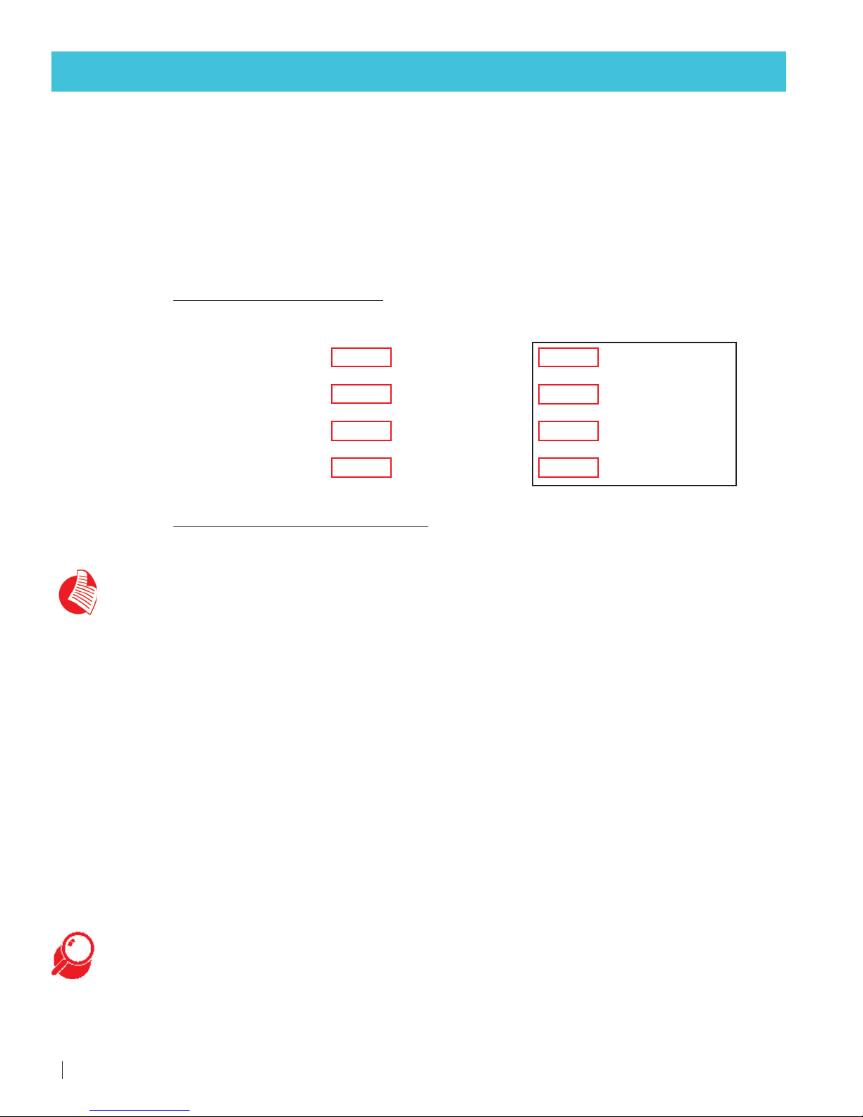
Controller Warnings
•Low EC
•High pH
•Low fertilizer/acid flow rate
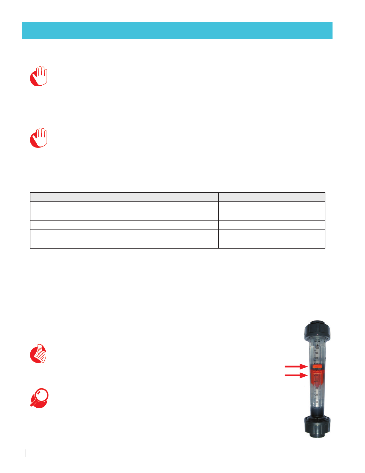
Visual Flow Meter Reading
•Low fertilizer/acid flow rate
Action
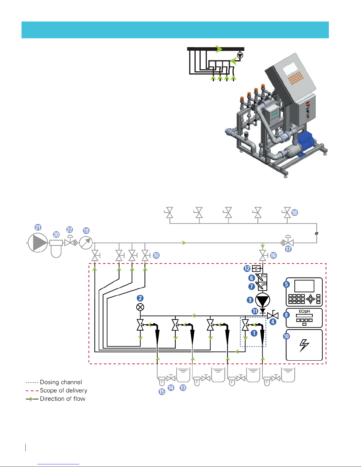
1) Check that there is fertilizer/acid solution in the stock tank A.
2) Check that the stock tank manual valve Bis in the OPEN position.
3) Check that the fertilizer/acid filter Cis clean - If not, it should be dismantled and thoroughly cleaned.
4) Check the fertilizer/acid line D(from the stock tank to the dosing channel) for leaks and breaches
and make sure all the connectors are tightened.
5) Make sure the dosing channel's needle valve Eis open according to the reference data in the
FERTIKIT Hydraulic Conditions Checklist.
6) Visually check the needle valve Efor chemical damage (internal deformation). If internal deformation is present,
replace the needle valve.
7) Visually check the needle valve Efor clogging. If clogging is present - thoroughly clean the needle valve.
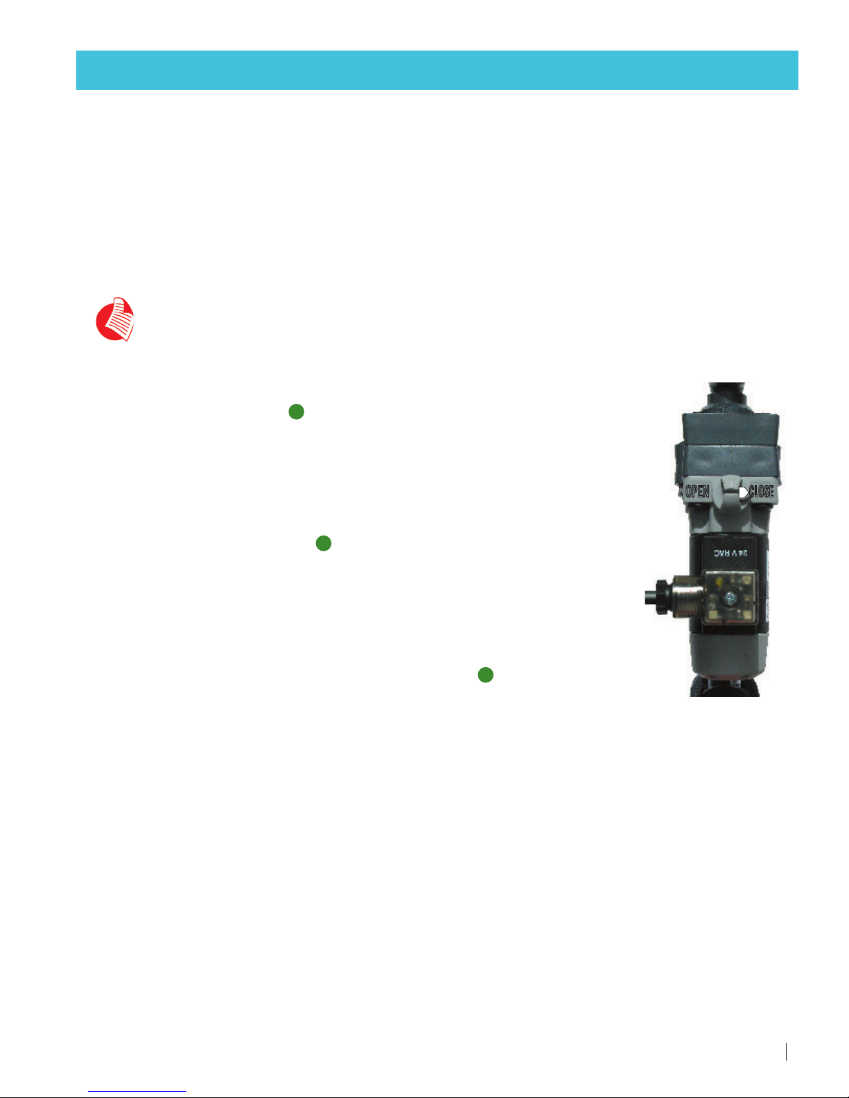
8) Check that the dosing valve Fis functioning:
With the controller in MANUAL mode, set the dosing valve Fto ON (see the Controller Manual).
The LED on the dosing valve should be lit.
- If it is not - have a qualified electrician check the dosing valve's cable for electrical continuity.
- If the cable is in working order - check the controller (see the Controller Manual).
-
If the controller and the cable are in working order - toggle the dosing valve
Fto OFF and again to ON
in the controller (see the Controller Manual). A 'Click' should be heard from the dosing valve with
each
toggle
- If a 'Click' is not heard, replace the dosing valve (consult your Netafim Dealer).
- If a 'Click' is heard and the dosing valve Fstill does not open - disconnect the dosing valve from the dosing
channel and with the dosing valve set to ON in the controller (see the Controller Manual), check for clogging
by injecting water at low pressure through the dosing valve.
TROUBLESHOOTING