Netafim Fertikit 3G User manual

FERTIKIT
™3G
INSTALLATION MANUAL
V 002.01 - OCTOBER 2020

© COPYRIGHT 2020, NETAFIM™
NO PARTS OF THIS PUBLICATION MAY BE REPRODUCED, STORED IN AN AUTOMATED DATA FILE OR MADE PUBLIC IN
ANY FORM OR BY ANY MEANS, WHETHER ELECTRONIC, MECHANICAL, BY PHOTOCOPYING, RECORDING OR IN ANY
OTHER MANNER WITHOUT PRIOR WRITTEN PERMISSION OF THE PUBLISHER.
ALTHOUGH NETAFIM™ TAKES THE GREATEST POSSIBLE CARE IN DESIGNING AND PRODUCING BOTH ITS PRODUCTS
AND THE ASSOCIATED DOCUMENTATION, THEY MAY STILL INCLUDE FAULTS.
NETAFIM™ WILL NOT ACCEPT RESPONSIBILITY FOR DAMAGE RESULTING FROM USE OF NETAFIM'S PRODUCTS OR
USE OF THIS MANUAL.
NETAFIM™ RESERVES THE RIGHT TO MAKE CHANGES AND IMPROVEMENTS TO ITS PRODUCTS AND/OR THE
ASSOCIATED DOCUMENTATION WITHOUT PRIOR NOTICE.
FOREIGN LANGUAGES
In the event that you are reading this manual in a language other than the English language, you
acknowledge and agree that the English language version shall prevail in case of inconsistency or
contradiction in interpretation or translation.

ELECTRICAL HAZARD
Contains instructions aimed at preventing bodily injury or direct damage to the FertiKit™ 3G
and/or the infrastructure in the presence of electricity.
WARNING
Contains instructions aimed at preventing bodily injury or direct damage to the crops, the
FertiKit™ 3G and/or the infrastructure.
CAUTION
Contains instructions aimed at preventing unwanted system operation, installation or conditions
that, if not followed, might void the warranty.
ATTENTION
Contains instructions aimed at enhancing the efficiency of usage of the instructions in the
manual.
NOTE
Contains instructions aimed at emphasizing certain aspect of the operation of the system or
installation.
SAFETY FOOTWEAR
Contains instructions aimed at preventing foot injury.
TIP
Provides clarification, tips or useful information.
ACID HAZARD
Contains instructions aimed at preventing bodily injury or direct damage to the crops, the
product and/or the infrastructure in the presence of acid.
PROTECTIVE EQUIPMENT
Contains instructions aimed at preventing damage to health or bodily injury in the
presence of fertilizers, acid or other chemicals.
EXAMPLE
Provides an example to clarify the operation of the settings, method of operation or installation.
The values used in the examples are hypothetical. Do not apply these values to your own
situation.
The symbols used in this manual refer to the following:
SYMBOLS

CONTENTS
Introduction
General instructions
Safety instructions
When using acid/chemicals
Description
Introduction
Advantages
Basic functions
Operating principle
Modularity
Compatibility
Service
Maintenance
The 8 modes
PL modes (PL/PS/PR/RL)
PB mode
SP mode
MS mode (MS/RS)
IL mode
ST mode
PD mode
MX mode
Dimensions and weighs
6
6
7
8
8
8
9
9
9
9
9
9
10
12
14
16
18
20
22
24
26

CONTENTS
On-site preparations
Hydraulic infrastructure preparation
Electrical preparation
Installation
Unpacking and placement
Hydraulic installation
Electrical installation
System operation
Preparations for running the FertiKit™
Running the FertiKit™
Calibration
Calculation of dosing channels opening percentage
Simulation with a 10 liter (2 US gal) bucket of water
Calibration of the FertiKit™ while irrigating
Commissioning
Warranty
Appendix
Dosing booster electrical data
28
33
34
34
36
37
38
40
40
42
44
45
46

6 FERTIKIT 3G INSTALLATION MANUAL
INTRODUCTION
General instructions
• Installation must be performed by authorized technicians only.
• Refer to your supervisor if problems occur during installation procedure.
• Installation should be performed on a hard, leveled floor or on a flat, hard, leveled plate.
• Do not apply force or pressure on components during the installation procedure.
• Verify that field components work properly.
• Make sure fertilizers and acid are on site at time of installation.
Electricity
• Ensure that suitable electrical power supply is available in the vicinity of the installation for the FertiKit™
electrical connection (see Electrical preparation, page 33).
• Ensure an electrical socket available in the FertiKit™ vicinity, for installation and for service purposes.
Safety instructions
•All safety regulations must be applied.
•Ensure that the installation is carried out in a manner that prevents leaks from the FertiKitTM,
the fertilizer/acid tanks and lines, the peripherals and the accessories (contaminating the
environment, soil or ambient area).
•When using acid always observe the acid manufacturer's safety instructions.
•Electrical installation should be performed by an authorized electrician only.
•The electrical installation must comply with the local safety standards and regulations.
•Installation should be performed by authorized technicians only.
•Protection provided by the equipment can be impaired if the equipment is used in a manner other than
that specified by the manufacturer.
WARNING
In agricultural environment - always wear protective footwear.
CAUTION
When opening or closing any manual valve, always do it gradually, to prevent damage to the
system by water hammer.
CAUTION
Read the Safety instructions chapter before beginning installation of the FertiKit™ 3G dosing unit.
WARNING
Always use protective equipment, gloves and goggles when handling fertilizers, acid and
other chemicals!
NOTE
The maximum sound level produced by the equipment does not exceed 70dB.
WARNING
Measures must be taken to prevent fertilizer infiltration of the water source, to avoid water pollution.

FERTIKIT 3G INSTALLATION MANUAL 7
INTRODUCTION
When using acid/chemicals
ACID HAZARD
When using acid - always observe the acid manufacturer's safety instructions.
WARNING
Always use protective equipment, gloves and goggles when handling fertilizers, acid and
other chemicals!
WARNING
Exceeding the recommended acid concentrations will damage the dosing channels.
WARNING
Substances
such as chemicals for pest/disease control might be corrosive and damage the
FertiKit™ 3G. When using any substance
other than
fertilizers or acids not exceeding the
concentrations in the table above, always observe the manufacturer's instructions for corrosivity.
In case of any doubt, contact your Netafim™ local representative.
CAUTION
There are fertilizer combinations that at high concentration might induce crystallization in the FertiKit's
lower manifold and cause clogging of the pipes.
Fertilizer combinations prone to induce crystallization:
•
Calcium Nitrate + Ammonium Sulfate => Calcium Sulfate
•
Calcium Nitrate + Potassium Sulfate => Calcium Sulfate
•
MKP + Calcium Nitrate => Calcium Phosphate
•
MAP + Calcium Nitrate => Calcium Phosphate
•
Phosphoric acid + Calcium Nitrate => Calcium Phosphate
When injecting these fertilizer combinations:
•
Make sure to dilute each fertilizer to the allowed concentration in the fertilizer tank prior to
injection through the FertiKit™.
•
Imediately after each injection of any of the fertilizer combinations above, flush the FertiKit™ with
clean water for at least 2 minutes.
In case of doubt regarding the use of any
combination of
fertilizers, contact your Netafim™ local
representative.
ATTENTION
When dosing acid, use a dosing channel fitted with the appropriate components according to
the type
and concentration of acid used*:
For pH correction
For maintenance of drippers
Type of dosing channel
Diaphragm
and O-rings
Nitric acid
(HNO3)
Phosphoric
acid
(H3PO4)
Sulfuric acid
(H2SO4)
Potassium
hydroxide
(KOH)
Acetic acid
(CH3COOH)
Hydrochloric
(HCl)
Hydrogen
peroxide
(H2O2)
Chlorine (as
(hypochloride
For diluted acid EPDM <3% <85% <30% <35% <30% <10% <30% <1%
For concentrated acid
Viton <40% <85% <90% <10% <5% <33% <50% <10%
% is by weight at 21oC (70oF)
*The table indicates the resistance of the dosing channel components to acid,
and is not a recommendation to use the acids mentioned.

8 FERTIKIT 3G INSTALLATION MANUAL
DESCRIPTION
Introduction
The FertiKitTM 3G is a fully configurable fertilizer/acid dosing unit - a highly cost-effective solution for
precise NutrigationTM.
Based on a standard platform, the FertiKitTM offers 7 different operation modes, selectable according
to the site conditions, in order to maximize usage of available water flow rate and pressure on the main
irrigation line, ensuring the highest efficiency with minimum investment.
The FertiKitTM can accommodate a variety of dosing channels, dosing boosters, controllers, peripherals and
accessories to meet a vast range of applications and infrastructure constraints.
Capacity range
The FertiKitTM ensures a satisfactory mixture in an extremely vast range of flow capacities.
It will accommodate a 0.1 Ha (0.25 Acres) nursery or a 400 Ha (1000 Acres) sugar cane plantation.
Main line pressure range: up to 8.5 bars (123.0 PSI).
Main line flow rate range: from 1.0 to 700.0 m3/h (from 4.4 to 3000.0 GPM).
Advantages
•A modular NutrigationTM system for soil or substrate applications with minimum investment
•Efficient usage of water, fertilizers and energy
•Unrivaled range of irrigation water capacities
•Designed for any application where quantitative or proportional NutrigationTM is required
•Highly profitable price/performance ratio
•Venturi operating principle - no moving parts
•Fits easily into any existing irrigation system
•Precise NutrigationTM based on high-accuracy dosing channels
•Quick action dosing valves
•Available with up to 6 fertilizer/acid dosing channels
•NutrigationTM recipes can be changed quickly and efficiently
•Can be operated manually or fully computerized
•NMC and other controllers can be assembled on the FertiKitTM for advanced NutrigationTM control
•
A wide variety of accessories and peripherals can be integrated into the FertiKitTM to enhance its functions
•High-quality components and PVC pipe work
•Aluminum, corrosion-resistant frame with adjustable legs
•Easy to install and to maintain
•Made by Netafim™
Basic functions
The FertiKitTM supports the following NutrigationTM functions:
•Fully controlled dosing and mixing of fertilizers/acid with source water into a homogenous nutrient
solution.
•EC/pH correction of the nutrient solution.
•Water pre-treatment

FERTIKIT 3G INSTALLATION MANUAL 9
DESCRIPTION
Operating principle
The FertiKitTM doses the various fertilizers and acid into a homogeneous solution and injects it into the
irrigation water main line. The suction of the fertilizers and acid in the dosing channels is based on the
Venturi principle. This requires a pressure differentiation - available on the main line or supplied by the main
line pump or the FertiKit's dosing booster.
Modularity
The modular FertiKitTM 3G concept is based upon an array of interchangeable components that enables
rapid assembly of a wide range of configurations.
Each FertiKitTM is delivered according to the precise customer’s order, either fully factory assembled or
assembled by the local dealer.
The dealer stocks the assortment of the FertiKitTM interchangeable components.
This concept enables the dealer to assemble any specific FertiKitTM according to the customer’s
order, saving the need to stock a large quantity of fully assembled FertiKitTM units of various common
configurations.
The modular FertiKitTM 3G concept ensures prompt delivery schedules without delays!
Stock selection option
Enables the dosing of multiple fertilizers through a single dosing channel (in cases where simultaneous
dosing is not required). Suits all modes of FertiKitTM.Available in a wide variety of configurations, from a
single dosing channel with 2 fertilizers to as many dosing channels and fertilizers as required. For further
information, contact Netafim™.
Compatibility
The FertiKitTM 3G can be incorporated in an existing or a planned project; in either case it offers a highly
cost-effective solution for NutrigationTM by taking maximum advantage of the infrastructure conditions.
Any available pressure surplus can be used for the FertiKit’s operation. In order to configure the most
cost-effective FertiKitTM, making the maximum use of available pressure.
ATTENTION
Calculations are either in metric or in US units - consistency in the type of units used is essential.
Service
Servicing the FertiKitTM 3G is a prompt and simple process. The dealer keeps a small quantity of
interchangeable components on hand, for replacement on site within a few minutes.
Maintenance
To prevent failures and extend the life cycle of the FertiKitTM, regular maintenance must be carried out
by the user, such as periodic rinsing of filters and calibration of the EC/pH sensors. For full maintenance
instructions, see Maintenance in the User Manual (The User Manual is provided with the FertiKit™
and can be downloaded at https://www.netafim.com/en/digital-farming/netbeat/Fertigation/fertikit/).
The 8 modes
Each one of the FertiKit™ 3G 8 modes depicted on the folowing pages fits a specific infrastructure
configuration.

10 FERTIKIT 3G INSTALLATION MANUAL
DESCRIPTIONDESCRIPTION
Dosing channel
Scope of delivery
Direction of flow
14
15 13
16
17
18
19
20
21
16
5
8
10
1
2
3
4
6
7
9
11
12
26
27
22
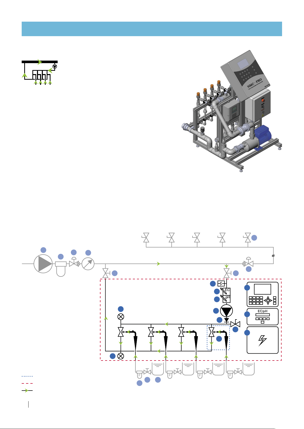
PL modes (PL/PS/PR/RL)
Operating principle: The pressure differential required to
generate fertilizer suction via the Venturis is produced by a
booster pump integrated in the FertiKitTM.
These modes of operation, where the lower manifold is under
low pressure (around 0 bars/PSI), permits the use of high-efficiency
Venturis with high suction capacity and low motive flow consumption.
Flow rate: 20 - 700 m³/h (85 - 3000 GPM)
Suitable for main line pressure:
PL
: 2.5 - 6.5 bars (36 - 94 PSI).
PR
with PRV 27: 6.5 - 8.5 bars (94 - 123 PSI)
PS
with PSV 26 : Based on cavitation risk.
RL
with PRV 27 and PSV 26 : 2.5 - 8.5 bars (36 - 123 PSI)
Dosing channels:
Accommodates a wide variety of dosing channels for fertilizer
and concentrated/diluted acid:
•50Hz: Up to 6 x 50 - 1000 l/h (13 - 265 GPH)
•60Hz: Up to 5 x 50 - 1000 l/h (13 - 265 GPH)
•60Hz: Includes compensation channel
•Optional - Concentrated acid channel, 50 l/h (13 GPH).
Controller: NMC-Pro, NMC-XL, NMC-Junior, (Other controllers or manual system without controller - optional).
EC/pH: Single, monitoring and control.
Schematic diagram
Total fertilizer/acid suction capacity:
•50Hz: up to 6000 l/h (1585 GPH).
•50Hz: up to 5000 l/h (1320 GPH).

FERTIKIT 3G INSTALLATION MANUAL 11
Main parts of the PL modes (PL/PS/PR/RL) and infrastructure
The list below presents the main parts of the FertiKit™ PL modes (PL/PS/PR/RL) and the infrastructure
parts required for its operation as depicted in the Schematic diagram and the Typical setup drawing above.
Color code:
Supplied (part of the FertiKit™), Not supplied (part of infrastructure), Optional.
DESCRIPTION
Typical setup of the PL modes (PL/PS/PR/RL)
FertiKitTM 3G
13
14
15
16
17
18
19
20
21
22
16
1Dosing channel + Venturi
2
Upper manifold pressure gauge
3Lower manifold presure gauge
4Sampling outlet
5Controller
6EC sensor
7pH sensor
8EC/pH transmitter
9Dosing booster
10 Dosing booster switchbox
11 Check valve
12 Pressure switch
13 Fertilizer/acid stock tank
14 Manual valve (fertilizer)
15 Fertilizer/acid filter
16 Manual valve (isolation)
17
Main line
pressure sustaining valve (PSV)
18 Irrigation valve
19 Water meter
20 Main line filter
21 Main line pump
22
Main line
pressure reducing valve (PRV)
26
Pressure sustaining valve (PSV)
27 Pressure reducing valve (PRV)
12 FERTIKIT 3G INSTALLATION MANUAL
DESCRIPTION
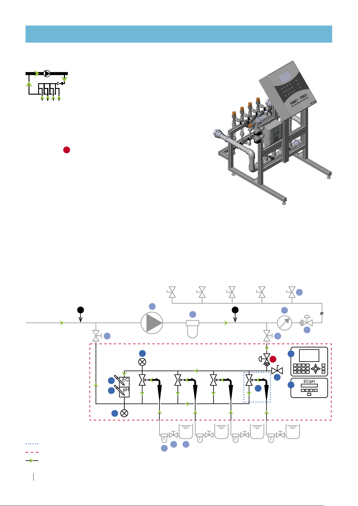
PB mode
Operating principle: The pressure differential required
to generate fertilizer suction via the Venturis is produced
by a booster pump integrated in the FertiKitTM.
This mode of operation, where the smaller system pump
is installed upstream from the Venturis, permits the use of a small
booster pump, reducing the investment required and saving energy.
This mode is suitable for relatively low flow rates and pressures.
Flow rate: 5 - 70 m³/h (22 - 300 GPM)
Suitable for main line pressure: 1.5 - 2.5 bars (22 - 36 PSI)
Additional conditions:
The pressure supplied by the dosing booster is added to the main line
pressure. Their sum (in the upper manifold) should not exceed
6.5 bars (94 PSI)
Dosing channels:
Accommodates a wide variety of dosing channels for fertilizer
and concentrated/diluted acid:
•Up to 4 x 50 - 370 l/h (13 - 100 GPH) •Optional - Concentrated acid channel, 50 l/h (13 GPH).
Total fertilizer/acid suction capacity - up to 1480 l/h (390 GPH).
Controller: NMC-Pro, NMC-XL, NMC-Junior, (Other controllers or manual system without controller - optional).
EC/pH: Single, monitoring and control.
Schematic diagram
22
14
15 13
16 17
18
19
20
21
16
5
8
10
1
2
3
4
6
7
9
11
12
Dosing channel
Scope of delivery
Direction of flow

FERTIKIT 3G INSTALLATION MANUAL 13
DESCRIPTION
Typical setup of the PB mode
FertiKitTM 3G
13
14
15
16
17
18
19
20
21
22
16
Main parts of the PB mode and infrastructure
The list below presents the main parts of the FertiKit™ PB mode and the infrastructure parts required for
its operation as depicted in the Schematic diagram and the Typical setup drawing above.
Color code:
Supplied (part of the FertiKit™), Not supplied (part of infrastructure).
1Dosing channel + Venturi
2
Upper manifold pressure gauge
3Lower manifold presure gauge
4Sampling outlet
5Controller
6EC sensor
7pH sensor
8EC/pH transmitter
9Dosing booster
10 Dosing booster switchbox
11 Check valve
12 Pressure switch
13 Fertilizer/acid stock tank
14 Manual valve (fertilizer)
15 Fertilizer/acid filter
16 Manual valve (isolation)
17
Main line
pressure sustaining valve (PSV)
18 Irrigation valve
19 Water meter
20 Main line filter
21 Main line pump
22
Main line
pressure reducing valve (PRV)

14 FERTIKIT 3G INSTALLATION MANUAL
DESCRIPTION
14
15 13
16
17
18
16
5
8
10
1
2
4
9
11
6
7
12
19
20
21 22
SP mode
Operating principle: The pressure differential required
to generate fertilizer suction via the Venturis is produced
by a booster pump integrated in the FertiKitTM.
This mode of operation, where the system pump
is installed upstream from the Venturis, permits the use of a smaller
booster pump, reducing the investment required and saving energy.
This mode is suitable for relatively low flow rates and pressures.
For applications that use very high concentration fertilizers and acid.
The solution has to be mixed in the main line.
SP mode is not equipped with a lower manifold.
(Can be supplied to the USA market with all parts inch-based to
facilitate replacement using locally available spare parts).
Flow rate: 5 - 250 m³/h (22 - 1100 GPM)
Suitable for main line pressure: 1.5 - 3.5 bars (22 – 51 PSI)
Dosing channels:
Accommodates a wide variety of dosing channels for fertilizer and concentrated/diluted acid:
•Up to 4 x 50 - 370 l/h (13 - 100 GPH) •Optional - Concentrated acid channel, 50 l/h (13 GPH).
Total fertilizer/acid suction capacity - up to 1480 l/h (400 GPH).
Controller: NMC-Pro, NMC-XL, NMC-Junior, (Other controllers or manual system without controller - optional).
EC/pH: Single, monitoring and control.
Schematic diagram
Dosing channel
Scope of delivery
Direction of flow

FERTIKIT 3G INSTALLATION MANUAL 15
DESCRIPTION
Typical setup of the SP mode
FertiKitTM 3G
13
14
15
16
17
18
19
20
21
22
16
Minimum required distances between the inlet and the fertilizer/acid outlets on the main line
A1
A2
A3
Description Required proportions
A1Distance between acid outlet and fertilizer outlet on the main line Minimum 75 cm (2.5 feet)
A2Distances between fertilizer outlets on the main line Minimum 30 cm (1.0 feet)
A3Distance between fertilizer outlet and FertiKitTM inlet on the main line Minimum 90 cm (3.0 feet)
Main parts of the SP mode and infrastructure
The list below presents the main parts of the FertiKit™ SP mode and the infrastructure parts required for
its operation as depicted in the Schematic diagram and the Typical setup drawing above.
Color code:
Supplied (part of the FertiKit™), Not supplied (part of infrastructure).
1Dosing channel + Venturi
2
Upper manifold pressure gauge
4Sampling outlet
5Controller
6EC sensor
7pH sensor
8EC/pH transmitter
9Dosing booster
10 Dosing booster switchbox
11 Check valve
12 Pressure switch
13 Fertilizer/acid stock tank
14 Manual valve (fertilizer)
15 Fertilizer/acid filter
16 Manual valve (isolation)
17
Main line
pressure sustaining valve (PSV)
18 Irrigation valve
19 Water meter
20 Main line filter
21 Main line pump
22
Main line
pressure reducing valve (PRV)
16 FERTIKIT 3G INSTALLATION MANUAL
DESCRIPTION
MS mode (MS/RS)
Operating principle: For systems operating under negative suction -
from a reservoir or a tank [max. height: 6 meters (20 feet)]
Utilizes the main line pump pressure.
Saves the need for a dosing booster.
Flow rate: 20 - 700 m³/h (85 - 3000 GPM)
Suitable for main line pressure:
Upstream from the pump: -0.3
-
+0.6 bar (-4
-
+9 PSI)
At the outlet of the pump: 2.5
-
6.5 bars (36
-
94 PSI)
RS
with PRV 27:
6.5
-
8.5 bars (94
-
123 PSI) at the FertiKitTM inlet.
Additional conditions:
Requires the connection of the FertiKit's outlet to the main line
upstream from the pump.
The main line pump should be able to deliver the flow rate required for the
operation of the FertiKit
TM
+ the field consumption.
Dosing channels:
Accommodates a wide variety of dosing channels for fertilizer and concentrated/diluted acid:
•Up to 6 x 50 - 1000 l/h (13 - 265 GPH) •Optional - Concentrated acid channel, 50 l/h (13 GPH).
Total fertilizer/acid suction capacity - up to 6000 l/h (1585 GPH).
Controller: NMC-Pro, NMC-XL, NMC-Junior, (Other controllers or manual system without controller - optional).
EC/pH: Single, monitoring and control.
Schematic diagram
14
15 13
16
17
18
19
20
21
16
5
8
1
2
3
4
6
7
27
P-0.3
-
+0.6 bar
(-4
-
+9 PSI)
P2.5
-
6.5 bar
(36
-
94 PSI)
Dosing channel
Scope of delivery
Direction of flow

FERTIKIT 3G INSTALLATION MANUAL 17
DESCRIPTION
Typical setup of the MS mode (MS/RS)
FertiKitTM 3G
13
14
15
16
17
18 19
20
21
16
Main parts of the MS mode (MS/RS) and infrastructure
The list below presents the main parts of the FertiKit™ MS mode (MS/RS) and the infrastructure parts
required for its operation as depicted in the Schematic diagram and the Typical setup drawing above.
Color code:
Supplied (part of the FertiKit™), Not supplied (part of infrastructure), Optional.
1Dosing channel + Venturi
2
Upper manifold pressure gauge
3Lower manifold presure gauge
4Sampling outlet
5Controller
6EC sensor
7pH sensor
8EC/pH transmitter
13 Fertilizer/acid stock tank
14 Manual valve (fertilizer)
15 Fertilizer/acid filter
16 Manual valve (isolation)
17
Main line
pressure sustaining valve (PSV)
18 Irrigation valve
19 Water meter
20 Main line filter
21 Main line pump
27 Pressure reducing valve (PRV)
18 FERTIKIT 3G INSTALLATION MANUAL
DESCRIPTION
14
15 13
18
21
5
8
10
1
2
3
4
6
7
9
11
12
2728 20
29
Dosing channel
Scope of delivery
Direction of flow
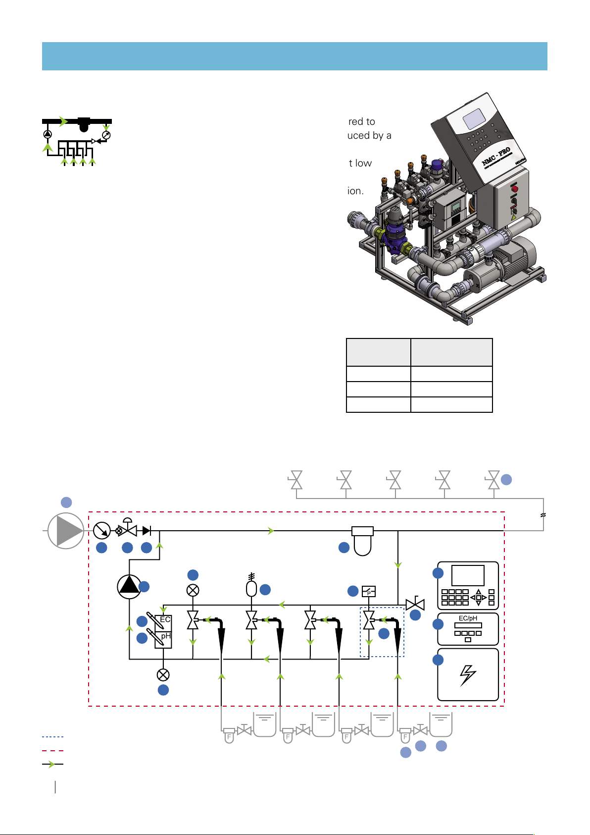
IL mode
Operating principle: The pressure differential required to
generate fertilizer suction via the Venturis is produced by a
booster pump integrated in the FertiKitTM.
In this mode of operation, the lower manifold is at low
pressure (around 0 bar/psi) this allows the use of high-efficiency
Venturis with high suction capacity and low motive flow consumption.
Since all the main line water flows through the system, slight
pressure losses at the FettiKit™ outlet should be considered
(see the table below).
Flow rate: 3 - 18 m³/h (13 - 85 GPM)
Suitable for main line pressure: 2.5 - 5.5 bars (36 - 79 PSI)
Dosing channels:
Accommodates a wide variety of dosing channels for fertilizer and
concentrated/diluted acid:
•50Hz: Up to 6 x 50 - 600 l/h (13 - 156 GPH)
•60Hz: Up to 3 x 50 - 600 l/h (13 - 156 GPH)
60Hz: Includes compensation channel
•Optional - Concentrated acid channel, 50 l/h (13 GPH).
Total fertilizer/acid suction capacity:
•50Hz: Up to 3600 l/h (950 GPH).
•60Hz: Up to 1800 l/h (475 GPH).
Controller: NMC-Pro, NMC-XL, NMC-Junior, (Other controllers or manual system without controller - optional).
EC/pH: Single, monitoring and control.
Schematic diagram
Flow rate
m³/h (GPM)
Pressure losse
bar (PSI)
5 (22) 0.1 (1.4 5)
10 (44) 0.3 (4.35)
15 (66) 0.6 (9.55)
pressure losses

FERTIKIT 3G INSTALLATION MANUAL 19
DESCRIPTION
Typical setup of the IL mode
FertiKitTM 3G
13
14
15
18
21
Main parts of the IL mode and infrastructure
The list below presents the main parts of the FertiKit™ IL mode and the infrastructure parts required for its
operation as depicted in the Schematic diagram and the Typical setup drawing above.
Color code:
Supplied (part of the FertiKit™), Not supplied (part of infrastructure).
1Dosing channel + Venturi
2
Upper manifold pressure gauge
3Lower manifold presure gauge
4Sampling outlet
5Controller
6EC sensor
7pH sensor
8EC/pH transmitter
9Dosing booster
10 Dosing booster switchbox
11 Check valve
12 Pressure switch
13 Fertilizer/acid stock tank
14 Manual valve (fertilizer)
15 Fertilizer/acid filter
18 Irrigation valve
20 Main line filter
21 Main line pump
27 Pressure reducing valve (PRV)*
28 Water meter*
29 Air release valve
28
20
+
*In the IL mode the pressure reducing valve (PRV)
27
and the water meter
28
are supplied as an integrated kit.
27

20 FERTIKIT 3G INSTALLATION MANUAL
DESCRIPTION
ST mode
Operating principle: For systems operating at low pressure -
from an on-ground reservoir or a tank
[max. height: 6 meters (20 feet)]
The dosing booster pump also serves as main line pump.
Supplied with a manual or a semi-automatic filter.
Flow rate: 1 - 16 m³/h (4.4 - 70 GPM)
Suitable for main line pressure:
Upstream from the pump: -0.3
-
+0.6 bar (-4
-
+9 PSI)
At the outlet of the pump: 2.0
-
5.5 bars (29
-
80 PSI)
Additional conditions:
When selecting a dosing booster, consider the required field flow
and the TC.
Dosing channels:
Accommodates a wide variety of dosing channels for fertilizer
and concentrated/diluted acid:
•Up to 6 x 50 - 600 l/h (13 - 156 GPH) •Optional - Concentrated acid channel, 50 l/h (13 GPH).
Total fertilizer/acid suction capacity - up to 3600 l/h (950 GPH).
Controller: NMC-Pro, NMC-XL, NMC-Junior, (Other controllers or manual system without controller - optional).
EC/pH: Single, monitoring and control.
Schematic diagram
Dosing channel
Scope of delivery
Direction of flow
20
14
15 13
17
18
5
8
10
1
2
3
4
6
79
11
12
19
29
P-0.3
-
+0.6 bar
(-4
-
+9 PSI)
16
Other manuals for Fertikit 3G
2
Table of contents
Other Netafim Farm Equipment manuals


