NetComm Wireless NTC-3000-01 User manual

N
N
TC-30
0
U
0
0 Seri
e
se
r
s – M2
M
r
Gu
M
Serial
ide
Modem

NTC
2
3000 Series – M2M S
Copyright
Copyright©2013 N
e
The information co
n
without prior writte
n
Please
n
Save Our Env
i
When this equipme
The cardboard box
dispose of this ele
c
municipal governm
e
Please be responsi
This manual c
NetComm NTC-30
0
NetComm NTC-30
0
NetComm NTC-30
0
1.0 - Initial docu
m
1.1 - Updated la
y
1.2 - Added Net
C
erial Modem
e
tComm Wireless Li
m
n
tained herein is pro
p
n
consent of NetCom
m
n
ote: This document
ironment
nt has reached the
e
x
, the plastic contain
e
c
tronic equipment al
o
ent.
ble and protect our
e
overs the follo
w
0
0-01
0
0-02
0
0-03
m
ent release
y
out of Hardware Ins
C
omm Wireless Ope
n
m
ited.
A
ll rights reser
v
p
rietary to NetComm
m
Wireless Limited.
is subject to change
e
nd of its useful life, i
t
e
d in the packaging,
o
ng with your househ
e
nvironment.
w
ing products:
tallation and Establi
s
n
AT Custom Applica
t
v
ed.
Wireless Limited. N
o
without notice.
t
must be taken to a
r
and the parts that m
a
old waste. You may
b
DOCUMEN
T
s
hing a Mobile broad
t
ion section based o
n
o
part of this docum
e
r
ecycling centre and
a
ke up this device c
a
be subject to penalti
e
T
VERSION
band connection se
c
n
software version 1.
e
nt may be translate
d
processed separat
e
a
n be recycled in ac
c
e
s or sanctions und
e
c
tions. Updated des
c
0.13
, transcribed, repro
d
e
ly from domestic wa
s
c
ordance with regio
n
e
r the law. Instead, a
s
c
riptions of interface
s
d
uced, in any form, o
ste.
n
ally established reg
u
s
k for disposal instru
c
s
.
www.netcommwirele
s
r by any means
u
lations. Never
c
tions from your
DATE
26/04/2013
24/06/2013
12/09/2013
s
s.com

NTC-3000 Series
www.netcommwireless.com
NTC 3000 Series –
M2M
Serial Modem
3
1.3 – Corrected RJ-45 to DB9 Serial/Power Adapter Cable diagram 27/11/2013
Table1‐DocumentRevisionHistory

NTC 3000 Series – M2M Serial Modem
4 www.netcommwireless.com
Table of Contents
Overview.............................................................................................................................................5
Safety and Product Care...........................................................................................................................6
Product Introduction...............................................................................................................................7
Physical Dimensions and Indicators .............................................................................................................8
LED Indicators........................................................................................................................................................................................................................................................................... 8
Physical Dimensions.................................................................................................................................................................................................................................................................. 8
Interfaces............................................................................................................................................9
Hardware Installation............................................................................................................................ 10
Inserting the SIM card ............................................................................................................................................................................................................................................................. 10
Mounting the device................................................................................................................................................................................................................................................................ 11
Connecting the Data / Power cables ...................................................................................................................................................................................................................................... 13
Establishing a Mobile broadband connection................................................................................................. 18
Using the Mini USB port .......................................................................................................................................................................................................................................................... 18
Using the RJ-45 connector...................................................................................................................................................................................................................................................... 20
Communicating with an NTC-3000 Series Modem ........................................................................................... 27
Dumb Terminal ........................................................................................................................................................................................................................................................................ 27
Open AT Application Framework ............................................................................................................................................................................................................................................ 29
NetComm Wireless Open AT Custom Application............................................................................................ 30
Command List ......................................................................................................................................................................................................................................................................... 30
General Operation................................................................................................................................................................................................................................................................... 43
Technical Data .................................................................................................................................... 48
Mini USB Connector ................................................................................................................................................................................................................................................................ 48
RJ-45 Connector...................................................................................................................................................................................................................................................................... 49
RJ-45 to DB9 Serial/Power Adapter Cable ............................................................................................................................................................................................................................. 49
Electrical Specifications .......................................................................................................................................................................................................................................................... 50
Environmental Specifications / Tolerances ............................................................................................................................................................................................................................. 50
Product Service and Support.................................................................................................................... 51
Troubleshooting....................................................................................................................................................................................................................................................................... 51
Web Based Product References............................................................................................................................................................................................................................................. 52
FAQs........................................................................................................................................................................................................................................................................................ 52
Appendix A: Tables............................................................................................................................... 53
Legal and Regulatory............................................................................................................................. 54

www
.netcommwireless.com
Ove
r
Introducti
o
This document det
a
Target U
s
This document is e
x
understanding of s
e
Prerequis
A computer with a
t
configuration has b
Notation
The following symb
The following note
r
The following note
p
The following note
p
r
view
o
n
a
ils the process of c
o
s
ers
x
pected to be utilise
d
e
rial based technolo
g
ites
t
erminal emulation p
r
een completed.
ols are used in this
m
r
equires attention
p
rovides a warning
p
rovides relevant inf
o
o
nfiguring the NTC-3
0
d
by system integrat
o
g
ies such as dialup
m
r
ogram (such as Hy
p
m
anual:
o
rmation.
0
00 Series device vi
a
o
rs or experienced h
a
m
odems, AT comma
n
erTerminal), a serial
a
a terminal emulatio
ardware installers w
h
n
ds and legacy data
port, an appropriate
n
program (such as
H
h
o are comfortable
w
collection devices.
power supply and a
H
yperTerminal) as w
e
ith all aspects of IP
b
device to connect t
o
NT
C
NTC 30
0
ell as mounting and
d
b
ased networking an
o
the NTC-3000 Seri
e
C
-3000 Serie
s
0 Series –
M2M
Serial
d
eployment advice.
d possess an
e
s modem after
s
Modem
5

NTC
6
3000 Series – M2M S
Safe
t
The NTC-3000 seri
e
With reference to t
h
I
D
D
o
A
E
U
WARNING:
Disconnect the po
w
Transport
When transporting
t
In the
erial Modem
t
y an
d
e
s offers a hardened
h
e unpacking, install
a
Installation, configur
a
D
o not use or install
t
D
o not use or install
t
o
perating temperatu
r
A
rrange any cables i
E
nsure that the volta
g
U
se only a clean, dr
y
w
er line from the devi
and Han
d
t
he NTC-3000 Serie
s
event the product n
e
d
Pro
d
industrial enclosure
a
tion, use and maint
e
a
tion and disassemb
t
his product near wa
t
his product in extre
m
r
e range (-40°C to 8
5
n a manner such th
a
g
e and rated curren
t
y
cloth to wipe the d
e
ce before servicing.
d
ling
s
, it is recommended
e
eds to be returned,
e
d
uct
C
making it suitable fo
r
e
nance of your electr
o
ly should be perfor
m
t
er to avoid fire or sh
m
ely hot or cold area
5
°C).
a
t they are not likely t
o
of the power source
e
vice. Never apply c
h
to return the produc
t
e
nsure it is securely
C
are
r a variety of remote
r
onic device, the foll
o
m
ed by trained perso
n
ock hazard.
A
void e
x
a
s. Ensure that the d
e
o
be stepped on or
h
e
match the requirem
h
emical cleaners on
t
t
to the original pack
a
packaged with appr
o
deployment location
o
wing basic guidelin
e
n
nel only.
x
posing the equipm
e
e
vice is installed in a
n
h
ave items placed o
n
ents of the device.
D
t
he device.
a
ging. This ensures
t
o
priate padding to p
s
.
e
s are recommended
e
nt to rain or damp a
r
n
area where the tem
them.
o not connect the d
e
t
he product will not
b
r
event damage durin
d
:
r
eas.
m
perature is within th
e
e
vice to an inapprop
r
b
e damaged.
n
g courier transport.
www.netcommwirele
s
e
supported
r
iate power source.
s
s.com

NTC-3000 Series
www.netcommwireless.com
NTC 3000 Series –
M2M
Serial Modem
7
Product Introduction
Product Overview
Small-sized and rugged industrial-grade 3G modem for wireless data communication
Provides reliable RS232 serial data connectivity for various M2M applications
Supports standard AT command set
Supports various networks and service types UMTS/HSDPA/HSUPA & GSM/GPRS/EDGE
Embedded Internet and security protocol stacks
Wide input voltage range 5-36V DC suitable for diverse environments and applications
RS232 serial data connection and power input via RJ45 port
USB 2.0 port for communicating (e.g. Dial-up networking from Windows PC and Mac)
Supports Open AT and AirVantage
DIN rail and wall mount option with removable mounting bracket
SIM card reader with locking tray
Wide operating temperature range -40 to 85°C
Package Contents
The NTC-3000 series package consists of:
NTC-3000 Series Modem
Quick Start Guide
The following items are available as optional accessories:
External antenna
DB9 serial/power adapter cable
Mounting bracket
If any of these items are missing or damaged, please contact NetComm Support immediately by visiting the NetComm Support website at: http://support.netcommwireless.com/ .
Product Features
The NTC-3000 Series is a reliable solution for cost effective deployment in any data telemetry environment. Designed for reliable performance and universal installation it provides 3G
data connectivity for M2M applications enabling remote monitoring, control, management and reporting of industrial and commercial equipment.
The small and rugged form factor is ideal for applications such as metering, rail, road signs, security, transport and vending machines. It can also be used in SCADA (Supervisory
Control and Data Acquisition) scenarios to monitor, control or collect data from remote devices such as farm machinery, water monitoring devices and wind farms.
A serial connection on one end and a 3G connection on the other allows the devices to simply take the serial data and send it over 3G. When connecting through the RJ-45 port to the
serial port of your device, the broadband connection can be established using AT commands in a terminal emulator or through the use of a Windows Dial Up Networking profile. The
modem also comes equipped with a Mini USB port where a connection can be established through either a virtual COM port or Sierra Wireless’s AirCard Watcher application.
The lockable SIM tray along with the rugged nature of the device means you can be assured that your device is working reliably, regardless of the physical location.

NTC 3000 Series – M2M Serial Modem
8 www.netcommwireless.com
Physical Dimensions and Indicators
LED Indicators
The NTC-3000 Series uses two LEDs to display the current system and connection status.
LED INDICATOR COLOUR DEFINITION
Power
Off The Power is off.
Red The Power is on and the NTC-3000 is operating normally.
3G
Off The NTC-3000 is not connected to a 3G network.
Slow flashing green The NTC-3000 is attempting to connect to a 3G network.
Quick flashing green Data is moving across the 3G connection.
Table2‐LEDIndicators
Physical Dimensions
The following page lists the physical dimensions of the NTC-3000 Series as well as the physical dimensions of the mounting bracket which can be used to attach the NTC-3000 Series
to a Type-O DIN Rail or to provide a wall / ceiling mount.
Figure1‐NTC‐3000SeriesDimensions Figure2‐NTC‐3000SeriesMountingBracket
NTC-3000 SERIES
Length 74 mm
Width 24 mm
Height 57 mm
Weight
84g
(w/o mounting bracket and antenna)
MOUNTING BRACKET
Length 80 mm
Width 45 mm
Height 5 mm
Weight
10g
(w/o NTC-3000 attached)
Table3‐DeviceDimensionsTable4‐MountingBracketDimensions

www
.netcommwireless.com
Inter
f
The following interf
a
Note:
http:/
/
f
aces
a
ces are available o
n
RJ-45 (RS-232
D
Mini USB
The driver required
/
support.netcommwi
n
the NTC-3000 Seri
e
INTERFACE
D
B-9 adapter / Power)
for the mini USB virt
u
reless.com/product/
m
e
s:
Tab
u
al COM port and
A
i
r
m
2m/ntc-3000
Provides a serial interf
a
and dial-up networking
DB-9 adapter / power
c
information.
Provides a serial interf
a
networking. Requires t
h
modem may be power
e
le5‐IntegratedD
e
r
Card Watcher appli
c
FUNCT
a
ce via a standard Windo
w
. The serial modem may al
c
able. Refer to the Technic
a
ce via a virtual COM port
f
h
at the SWI driver and 3G
w
e
d from the Mini USB port.
e
vices
c
ation are available f
I
ON
s modem for AT comman
d
so be powered from this i
n
a
l Data section of this man
f
or AT command communi
c
w
atcher application are in
s
r
om the NTC-3000 S
e
NT
C
NTC 30
0
d
communication
n
terface using the
n
ual for more
cation and dial-up
s
talled. The serial
eries Product Suppo
C
-3000 Serie
s
0 Series –
M2M
Serial
rt page at:
s
Modem
9

NTC 3000 Series – M2M Serial Modem
10 www.netcommwireless.com
Hardware Installation
Inserting the SIM card
Please ensure that the NTC-3000 is not connected to the power cable before proceeding.
1. Push the small yellow button besides the SIM card holder.
Figure3–AccessingtheNTC‐3000SIMCardSlot
2. Insert the SIM card into the holder with the golden SIM conductor pins facing up.
Figure4‐InsertingaSIMCardintotheNTC‐3000SIMCardHolder

NTC-3000 Series
www.netcommwireless.com
NTC 3000 Series –
M2M
Serial Modem
11
3. Insert the loaded SIM card holder with the SIM conductor pins facing down into the NTC-3000.
Figure5–FaceDownInsertionoftheSIMCardandSIMCardHolder
Mounting the device
The NTC-3000 series modem can be mounted on the wall or a DIN rail by using the mounting bracket. The mounting bracket is made from polyamide, which is a flexible material.
Mounting the NTC-3000 series modem is as simple as bending the mounting bracket to snap into place on the Type-O (Top Hat) DIN rail. This holds the NTC-3000 series modem in
place securely.
Alternatively, the mounting bracket can be screwed onto a wall to provide a permanent fixture.
DIN rail mounting
The NTC-3000 Series mounting bracket has been designed to fit a TS 35 Type-O DIN rail with a 25mm core.
1. Bend / Flex the mounting bracket at the bend line so that the ridges are able to ‘hold’ onto the DIN rail edges as per the diagram above. You also have the option of securing
the mounting bracket further by screwing it into place on the rail.
Figure6‐NTC‐3000‐MountingBracket‐DINRail

NTC 3000 Series – M2M Serial Modem
12 www.netcommwireless.com
2. Once the bracket is attached to the DIN rail, slide the NTC-3000 Series modem into the mounting bracket to securely fix it in place.
Figure7‐SecuringtheNTC‐3000MountingBrackettotheDINRail
Wall Mounting
1. Select a position on the wall where you would like to mount the NTC-3000 Series modem. Attach the mounting bracket to the chosen wall or ceiling by using the 4 screw holes
(screws not included).
2. Once the bracket is attached to the DIN rail, slide the NTC-3000 Series modem into the mounting bracket to securely fix it in place.

www
.netcommwireless.com
Connecti
n
There are two meth
V
V
Connecting vi
a
1. Connect the
2. Plug the opti
NTC-3000.
3. Connect a c
o
Please n
the mini-
n
g the Dat
a
ods of connecting th
V
ia RJ-45 connector
V
ia USB 2.0 port usi
n
a
RJ-45 connec
t
optional antenna to
t
onal RS-232 data/p
o
o
mpatible power ad
a
ote: It is not possibl
e
-
USB cable.
a
/ Power
c
e NTC-3000 to your
using a DB9 serial/
p
n
g a Mini USB cable
t
or
Figure
t
he SMA connector
o
o
we
r
cable into the R
J
a
pter to the DC pow
e
e
to use the mini-US
B
c
ables
c
omputer:
ower adapter cable
8‐Connectingthe
R
o
f the NTC-3000.
J
-45 socket of the N
T
e
r
j
ack (2.1mm barrel
B
and Serial connecti
o
RJ‐45Ethernet/P
o
T
C-3000 and then pl
u
l
) of the RS-232 data
/
on concurrently. Ma
k
o
werCabletotheN
u
g the serial port () e
/
power cable and th
e
k
e sure any open co
n
TC
‐3000
nd into the COM por
t
e
n plug the power a
d
n
nection on the Seria
NT
C
NTC 30
0
r
t of the device that
w
d
apter into a power
o
a
l port is disabled be
f
C
-3000 Serie
s
0 Series –
M2M
Serial
w
ill connect to the
utlet.
f
ore connecting via
s
Modem
13

NTC 3000 Series – M2M Serial Modem
14 www.netcommwireless.com

www
.netcommwireless.com
Connecting vi
a
The mini USB conn
e
(such as HyperTer
m
Watcher applicatio
n
NetComm Wireless
website at http://w
w
The following proc
e
Note:
D
1. Open “My C
o
2. Double-clic
k
installation.
3. The End Us
e
location that
a
Mini USB port
ection enables com
m
m
inal). To configure
t
n
can also be used t
o
Support website at
h
w
w.sierrawireless.co
m
e
dure demonstrates
h
D
o not connect the
N
o
mputer” and navig
a
k
on the Watcher_Ge
n
e
r License Agreeme
n
the application is in
s
m
unication from a Wi
n
t
he internet connecti
o
o
establish the broa
d
h
ttp://support.netco
m
m
/support.aspx.
h
ow to install the Air
C
N
TC-3000 Series Rou
t
a
te to the folder whe
r
n
eric.msi file to open
Fi
g
n
t is displayed. If you
s
talled to, click the C
Figure10‐
AI
n
dows computer via
o
n settings of the rou
t
d
band connection an
d
m
mwireless.com/pro
d
C
ard Watcher applic
a
t
er to the computer
u
e you saved the Air
C
the installation wiza
r
ure9‐
A
IrCardWa
t
agree with the term
s
h
ange button and c
h
I
rCardWatcherIns
t
a virtual COM port.
T
ter, the AirCard Wat
c
d includes the drive
r
d
uct/m2m/ntc-3000.
o
a
tion on Windows X
P
u
ntil the AirCard Wat
c
C
ard Watcher applic
a
r
d. The AirCard Wat
c
t
cherInstallShield
W
s
of the agreement s
e
h
oose the location to
t
allShieldWizardE
n
T
he NTC-3000 Serie
s
c
her application mus
r
necessary to install
o
r for the most up to
d
P
:
c
her application has
a
tion.
c
her Installation Wel
c
W
izardWelcomeSc
r
e
lect “I accept the te
install the applicatio
n
n
d‐UserLicenseAgr
e
s
modem can then b
e
t
be installed on you
r
t
he modem on your
c
d
ate version of the s
o
been installed.
ome screen is displ
a
r
een
rms in the license a
g
n
. Click Next > to co
n
e
ementScreen
NT
C
NTC 30
0
e
configured via a te
r
r computer. The Sier
c
ompute
r
. It can be
d
o
ftware, please visit t
a
yed. Click Next > to
g
reement”. If you wa
n
n
tinue.
C
-3000 Serie
s
0 Series –
M2M
Serial
r
minal emulator
r
a Wireless AirCard
d
ownloaded from th
e
h
e Sierra Wireless
begin the
n
t to change the
s
Modem
15
e

NTC
16
3000 Series – M2M S
4. The installati
Verifying succ
e
To verify the driver
w
1. Click on the
2. Double click
3. Click on the
4. The Device
L
and you ma
y
If the Sierra Wirele
s
http://support.netco
erial Modem
on wizard will proce
e
e
ssful installati
o
w
as successfully ins
t
Start button and nav
k
on the System Cont
Hardware tab and th
L
ist displays the follo
y
wish to use this po
r
s
s COM ports are no
t
mmwireless.com
/
e
d to install the soft
w
Figu
o
n of the driver
t
alled, check in the
D
igate to the Control
P
rol Panel item.
en click the Device
M
wing COM ports. Ta
k
r
t to communicate wi
t
Figur
e
t
listed, please reboo
w
are and when it has
f
re11‐
A
IrCardWa
t
D
evice Manager for
e
P
anel option.
M
anage
r
button.
k
e note of the COM
p
t
h the modem via a t
e
e
12‐NTC‐3000US
B
t your computer and
finished, the InstallS
h
t
cherInstallShield
W
e
xtra COM ports. To
c
p
ort number of the Si
e
rminal emulator. In
t
B
DriverInstallatio
n
attempt the installat
i
h
ield Wizard Compl
e
W
izardCompleted
S
c
heck the Device M
a
erra Wireless AT Co
m
t
his example, it is C
O
n
‐DeviceManager
on again. If this still
f
ted screen is displa
y
S
creen
nager, perform the f
o
m
mand Port as this
w
O
M11.
Details
f
ails, please contact
N
y
ed. Click Finish to c
o
llowing steps:
w
ill vary depending o
NetComm Wireless
T
www.netcommwirele
s
lose the wizard.
n your environment
T
echnical Support at
s
s.com

NTC-3000 Series
www.netcommwireless.com
NTC 3000 Series –
M2M
Serial Modem
17

NTC
18
3000 Series – M2M S
Esta
b
Using the
The NTC-3000 Seri
e
1. Connect the
prompt you
f
2. When the PI
N
3. In many cas
e
to access th
e
4. Click Profile
s
When you a
r
erial Modem
b
lishi
n
Mini USB
e
s Routers can use t
NTC-3000 to your c
o
f
or the PIN to unlock
N
is verified, the Air
C
e
s you will be able t
o
e
configuration optio
s
from the menu on t
h
r
e done click Apply.
n
g a
M
port
he Sierra Wireless Ai
o
mputer using a mini
it. Enter the PIN and
C
ard Watcher applic
a
o
click the Connect b
ns.
h
e left and then clic
k
M
obil
rCard Watcher appli
USB cable. The Air
C
click SEND.
Figure
a
tion will be displaye
d
Figure14
‐
utton to establish a
c
to add a new
p
e br
o
cation to establish a
n
C
ard Watcher applic
a
13‐SIMlockedPI
N
d
:
‐
A
irCardWatcher
M
c
onnection immediat
e
p
rofile. Enter a Profil
e
o
adb
a
n
internet connectio
n
a
tion should automa
t
N
Prompt
M
ainScreen
e
ly if the software w
a
e
Name, Username
a
a
nd c
o
. To begin using the
t
ically start up and if
y
s able to determine
a
nd Password (if req
u
o
nne
c
NTC-3000 Series R
o
your SIM card is PI
N
a
default APN. If not,
u
ired) and APN (Acc
e
www.netcommwirele
s
c
tion
o
uter:
locked, it will
click the icon
e
ss Point Name).
s
s.com

NTC-3000 Series
www.netcommwireless.com
NTC 3000 Series –
M2M
Serial Modem
19
Figure15‐AIrCardWatcherOptions‐AddNewProfileScreen
5. With the Profiles menu option selected, use the Default Profile drop down list on the right side of the screen to select the profile you created and click OK.
Figure16‐AIrCardWatcherOptions‐ProfilesOptions
6. Click Connect to connect to the mobile broadband network. When you are connected, the Connect button changes to a Disconnect button.
Figure17‐AirCardWatcherApplication–Connected

NTC
20
3000 Series – M2M S
Using the
The NTC-3000 can
process using Win
d
1. Click Start a
n
2. Double click
3. On the Phon
4. Select Don’t
erial Modem
RJ-45 co
n
be used to dial up t
o
d
ows XP, however si
m
n
d then Control Pan
e
k
Phone and Modem
e and Modem Optio
n
detect my modem; I
n
necto
r
o
the internet and pr
o
m
ilar steps can be u
s
e
l.
Options.
n
s window, click Ad
d
will select it from a
Fi
g
o
vide networking usi
n
s
ed in other operatin
g
Figure18‐Contr
o
d
list and then click N
e
g
ure19‐
A
ddHard
w
n
g a standard serial
m
g
systems.
r
olPanel‐Phonea
n
e
xt.
w
areWizard‐Don'
t
m
odem driver. Exam
n
dModemOptions
t
DetectModemO
p
p
le screenshots are
s
tion
shown below to de
m
www.netcommwirele
s
onstrate this
s
s.com
Other manuals for NTC-3000-01
1
This manual suits for next models
2
Table of contents
Other NetComm Wireless Modem manuals
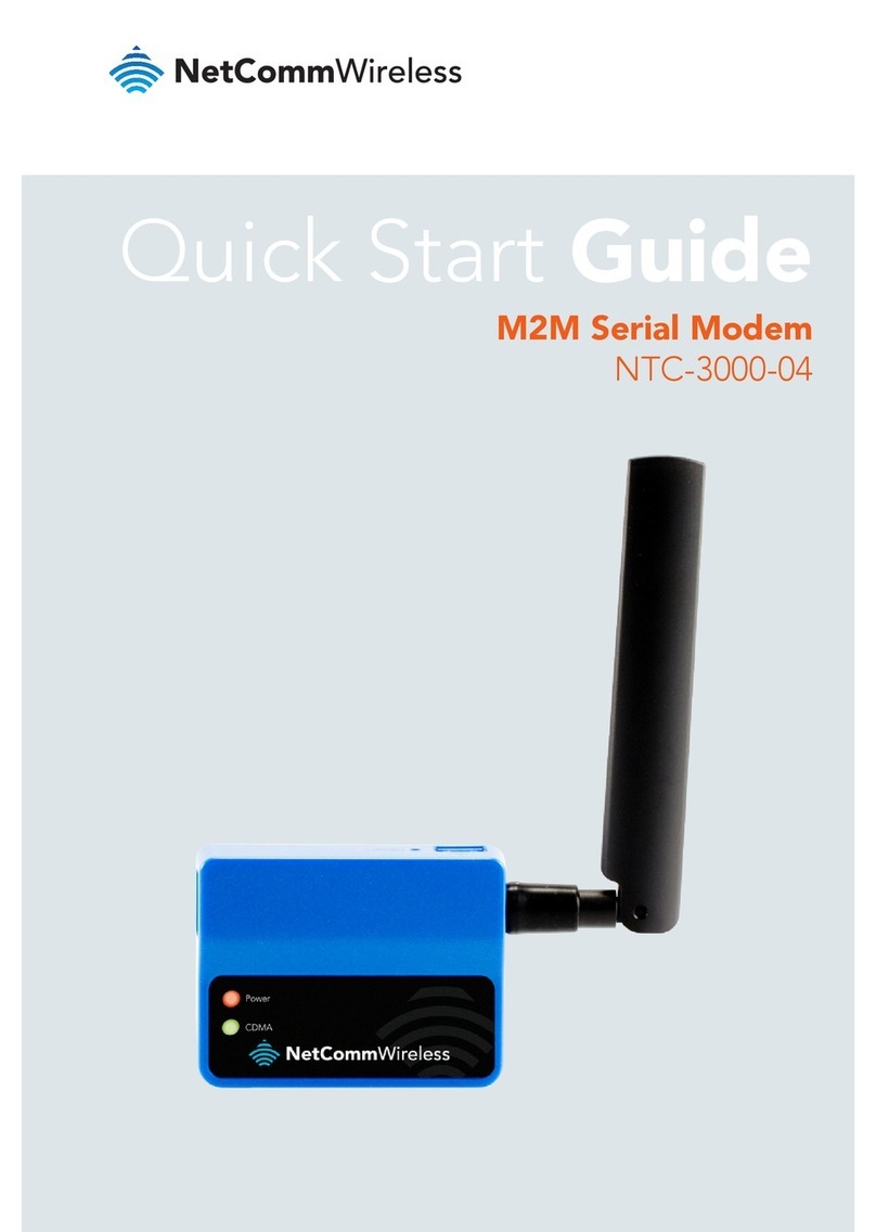
NetComm Wireless
NetComm Wireless NTC-3000-04 User manual

NetComm Wireless
NetComm Wireless Contact NF18ACV User manual
NetComm Wireless
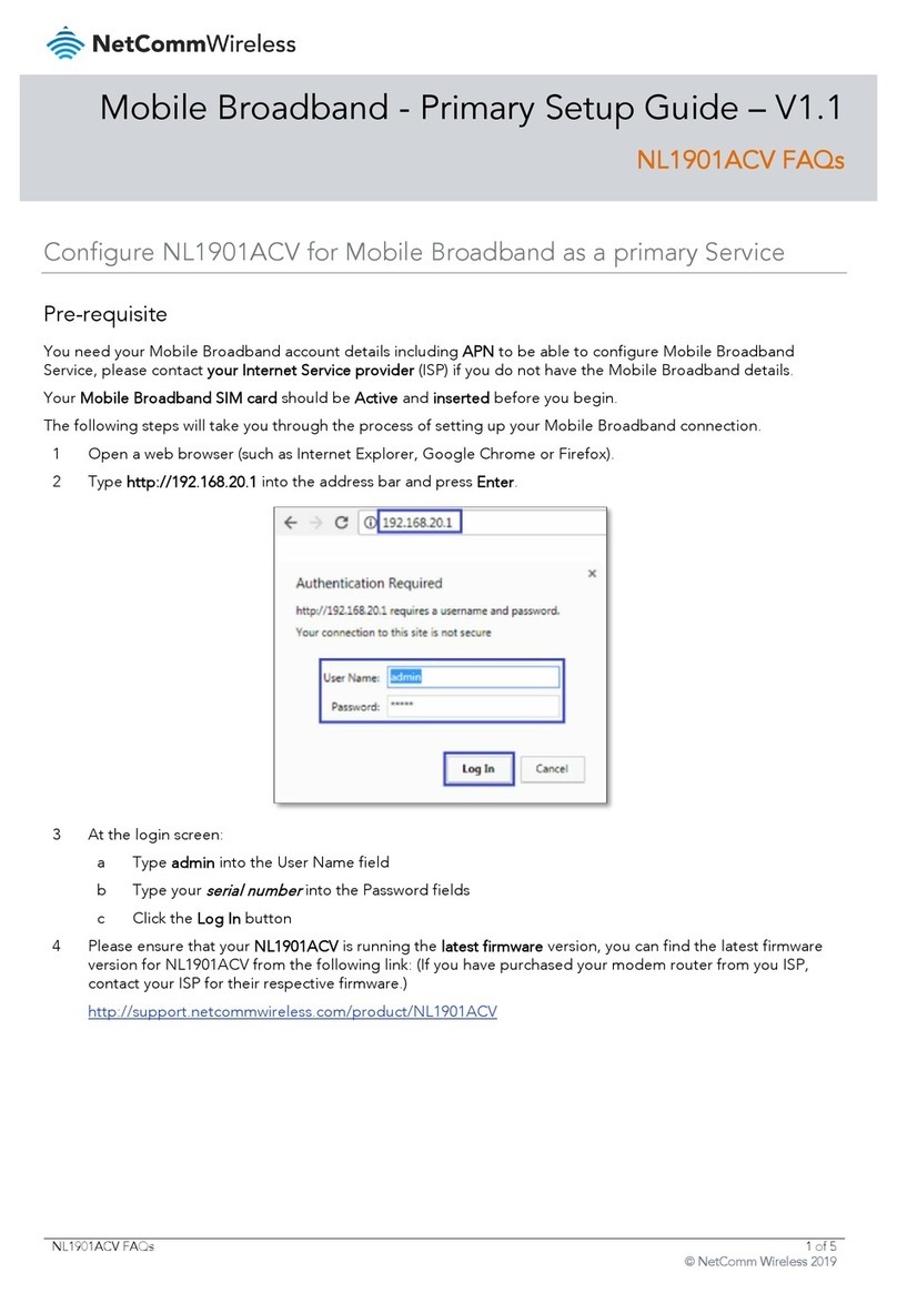
NetComm Wireless NL1901ACV User manual
NetComm Wireless
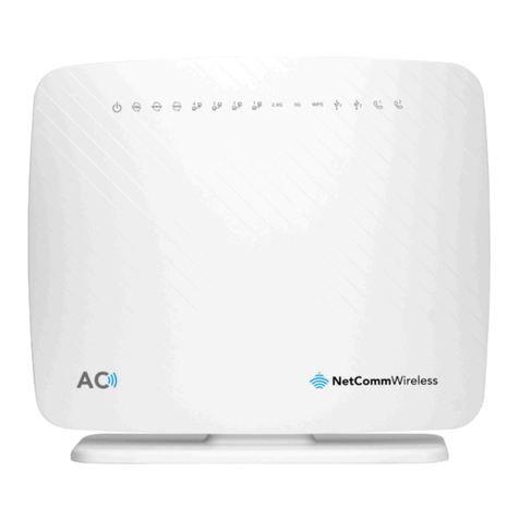
NetComm Wireless NF17ACV User manual
NetComm Wireless
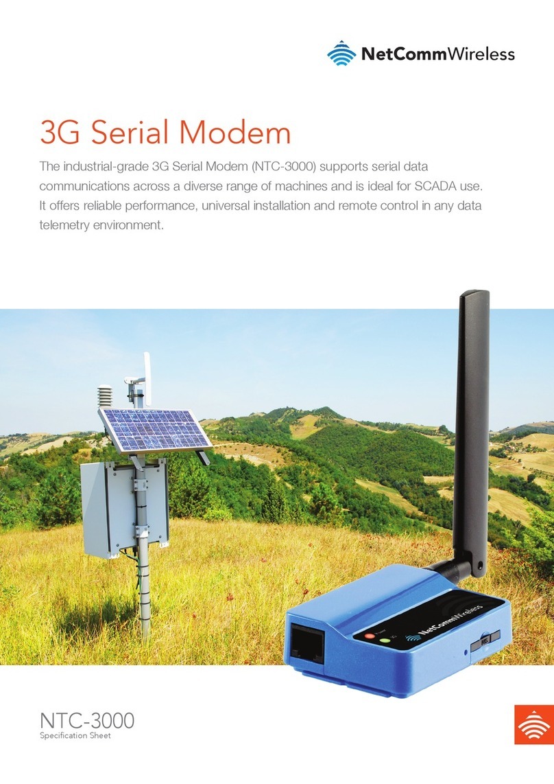
NetComm Wireless NTC-3000-01 User manual
NetComm Wireless
NetComm Wireless Contact NF18ACV User manual
NetComm Wireless
NetComm Wireless NB16WV-02 User manual
NetComm Wireless
NetComm Wireless 3GM2WN User manual
NetComm Wireless
NetComm Wireless NWL-221 User manual
NetComm Wireless
NetComm Wireless NTC-100 User manual
