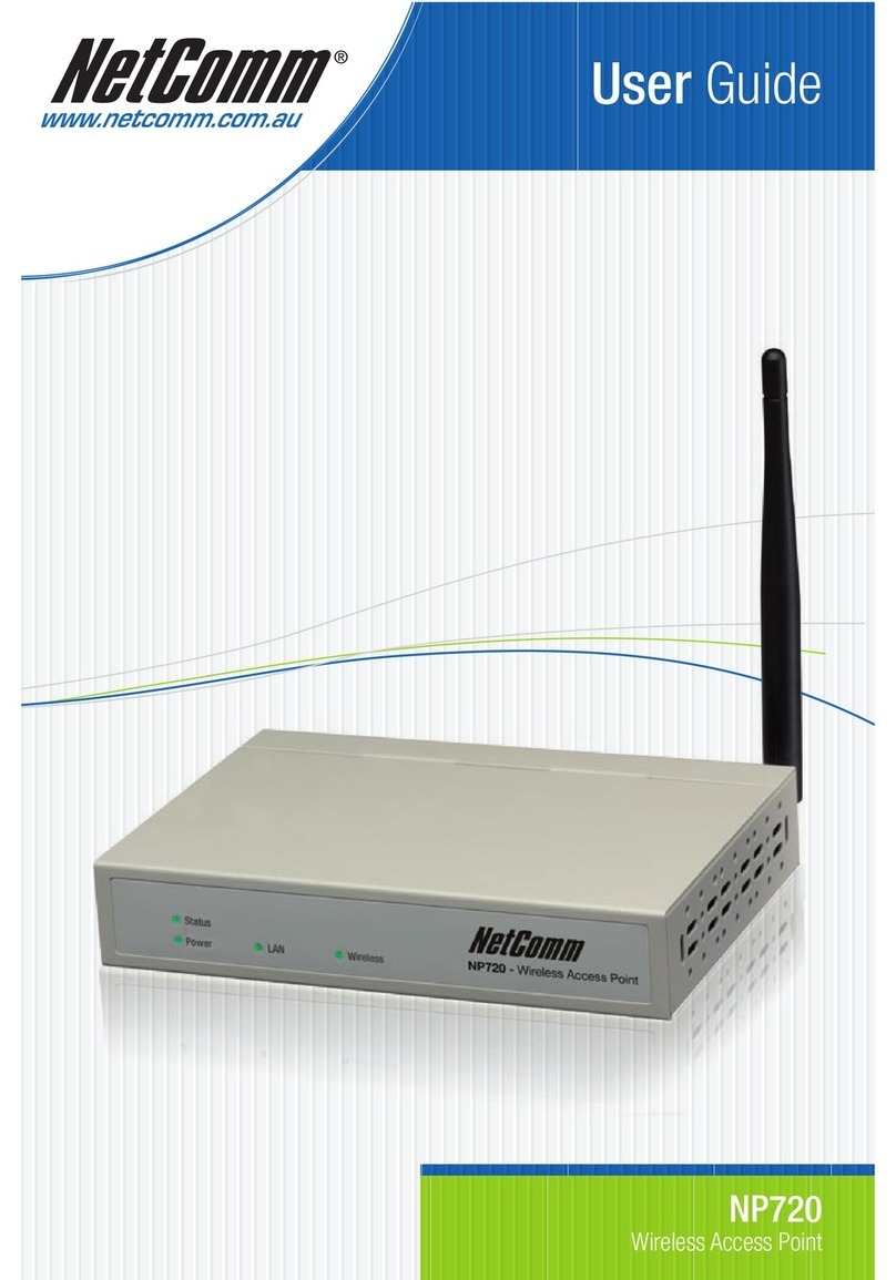
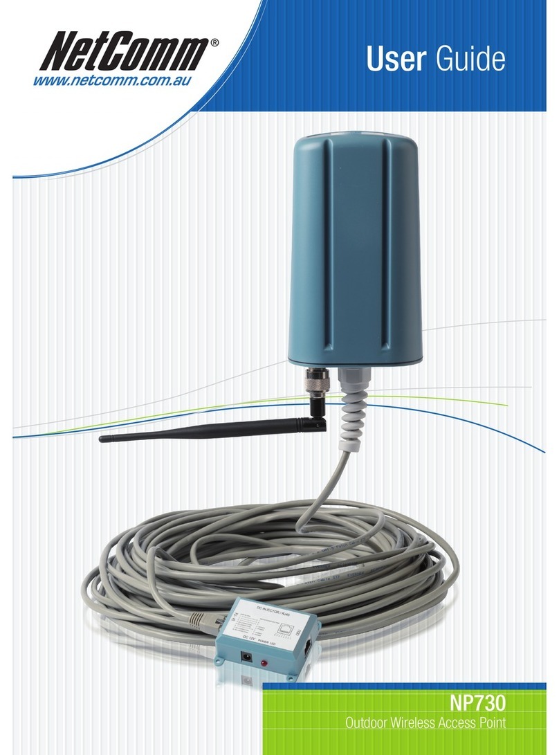
NetComm NP725 User manual

User Guide
NP725 User Guide
www.netcomm.com.au
NP725 - Wireless Access Point

Table of Contents
Chapter 1. Introduction .......................................................................................................................................1
1.1 Overview ...................................................................................................................................................1
1.2 Product Features ........................................................................................................................................1
1.3 Deployment Topology Examples...............................................................................................................2
Chapter 2. System Overview................................................................................................................................3
2.1 Package Contents.......................................................................................................................................3
2.2 Hardware ...................................................................................................................................................3
2.3 System Requirement and Preparation........................................................................................................5
Chapter 3. Installation.........................................................................................................................................6
3.1 Wireless LANAccess Point Connection ...................................................................................................6
3.2 Basic Configuration...................................................................................................................................7
Chapter 4. Web Management Interface............................................................................................................17
4.1 System .....................................................................................................................................................20
4.1.1 System Information .........................................................................................................................................20
4.1.2 Network Settings .............................................................................................................................................23
4.1.3 Management Services......................................................................................................................................24
4.2 AP............................................................................................................................................................25
4.2.1 Virtual AP Overview........................................................................................................................................25
4.2.2 General Settings...............................................................................................................................................28
4.2.3 VAP Configuration...........................................................................................................................................29
4.2.4 Security Settings..............................................................................................................................................30
4.2.5 Advanced Wireless Settings.............................................................................................................................33
4.2.6 Access Control Settings...................................................................................................................................34
4.3 WDS ........................................................................................................................................................37
4.3.1 WDS Link Overview.......................................................................................................................................37
4.3.2 WDS Link Settings..........................................................................................................................................38
4.4 Utilities ....................................................................................................................................................39
4.4.1 Change Password.............................................................................................................................................39
4.4.2 Configuration Save / Restore...........................................................................................................................40
4.4.3 System Upgrade...............................................................................................................................................41
4.4.4 Reboot..............................................................................................................................................................42
4.5 Status .......................................................................................................................................................43
4.5.1 System Overview.............................................................................................................................................43
4.5.2 Associated Client Status ..................................................................................................................................45
4.5.3 WDS List Status ..............................................................................................................................................46
4.5.4 Event Log ........................................................................................................................................................47
4.6 Online Help..............................................................................................................................................48
4.7 Legal & Regulatory Information .............................................................................................................48

Chapter 1. Introduction
1
Chapter 1. Introduction
1.1 Overview
This manual is written to assist system integrators, field engineers and network administrators in setting set up
NetComm NP725Access Points in their network environments. It contains step by step procedures and pictures to
guide users with basic network system knowledge to complete the installation.
NP725 is a Multi-ModeAccess Point, specially designed for connecting wireless networks for wider coverage.
NP725 provides features ofAccess Point (AP) and Wireless Distribution System (WDS) simultaneously. In the
Access Point mode, it supports up to eight VirtualAccess Points (VAPs) which could provide service in different
levels and much securer network. NP725Access Point also supports the most popular wireless authentication and
encryption standards which make flexible security policy possible by taking advantage of these Virtual Access Points.
Thus, there is an independent rule setting for each VirtualAccess Point that can be defined to meet the actual
requirements. In the Wireless Distribution System mode, it supports point-to-point or point-to-multipoint topology,
which could widely extend the wireless coverage.
1.2 Product Features
High Speed IEEE 802.11g and Backward Compatible with 802.11b
IEEE 802.11b/g + WDS (Bridge & Repeater, Point-to-Point, Point-to-Multiple-Point)
Dual IEEE 802.3af (PoE) Compliant with Link Failover
Multiple ESSIDs Capability
WDS for Extending Wireless Coverage
Supporting QoS & 802.11e WMM
Multiple Virtual APs & Capability of Client Isolation
Business-class WLAN Security & ClientAuthentications
MultipleAdministration Interfaces for Network Management
Dual-PoE with Link Failover
Antenna Diversity & detachable Antenna
IP50 Compliant

Chapter 1. Introduction
2
1.3 Deployment Topology Examples
The above deployment scenario illustrates a deployment example using three access points,AP-1, AP-2 and AP-3.
Three NP725s construct a network with wired and wireless segments.
The AP-2 plays the role as a wireless bridge.
All machines share the same DHCP server 192.168.1.1. Formatted: Bullets and
Numbering

Chapter 2. System Overview
3
Chapter 2. System Overview
2.1 Package Contents
The standard package of NP725 includes:
yNP725 x 1
yCD-ROM with product User Manual x 1
yConsole Cable DB9 Female to DB9 Male x 1
yStraight through Ethernet Cable x 1
yPower Adapter 12V, 1.5Ax 1
y2dBi Antenna x 2
yMounting Kit x 1
yGround Cable x 1
Note: It is recommended to keep the original packing materials in case of product service requirements. Any returned
product should be packed according to its original package content, together with its relevant packing materials used
for protecting the equipment from damage during delivery.
2.2 Hardware
On the top panel of the product, there are four LEDs that are used to indicate the system power, WLAN status, and the
link status of the two PoE Fast Ethernet ports. On the front panel, there are one power socket, one reset button, two
PoE LAN ports and one console port. The antenna is installed on the rear panel.

Chapter 2. System Overview
4
Rear Panel
Power Socket: Connects to the power adapter provided.
RESET Button
oPress the button to restart the system.
oPress and hold the button for 5 seconds to reset the system to factory default and restart the system.
LAN 1 / LAN2:
oThe LAN ports are used for connecting with wired networks. These two ports also support Power over
Ethernet (PoE).
Console:
oThe serial cable attaches here.Administrators can obtain IP address information of Ethernet ports
from the console port.
Antenna Connector: The antenna attaches here. NP725 supports 1 RF interface and 2 SMAconnectors for
antenna connection.

Chapter 2. System Overview
5
Top Panel
LED:
Power: ON indicates that power is on and OFF indicates that power is off.
LAN1/LAN2: OFF indicates no connection, ON indicates connection and BLINKING indicates transmitting
data.
WLAN: ON indicates system is ready.
2.3 System Requirement and Preparation
Preparations
A computer is needed to configure NP725 via its web management interface. After completing hardware installation,
the administrator can configure the NP725 via web browser with JavaScript enabled, such as Mozilla Firefox 2.0 or
Internet Explorer version 6.0 and the above.
The default LAN IP address of NP725 is listed as following:
IPAddress: 192.168.25.1
Subnet mask: 255.255.255.0
If the IP address of the administrator’s PC is not assigned via DHCP, then a static IP address assigned to the
administrator’s computer within the same subnet as NP725 is needed. The following listedAddress as examples:
IPAddress: 192.168.25.100
Subnet mask: 255.255.255.0
Note: Please refer to LEDs of the switch hub to verify the wired connection of both sides. After NP725's network
configuration completes, please switch back the original settings to fit the real network environment.

Chapter 3. Installation
6
Chapter 3. Installation
3.1 Wireless LAN Access Point Connection
Please follow the steps below to install the hardware of NP725.
1. Locate the wireless LAN access point at the best location. The best location for NP725 is usually at the center of a
wireless network.
2. Connect the wireless LAN access point to your other network equipment.
Connect an Ethernet cable to the NP725’s LAN port and connect the other end of the cable to a switch, a router, or
a hub. The access point will be connected to your existing wired LAN network.
3. There are two options to supply power to NP725.
1) Connect the DC power adapter to the power socket. Please note that using a different adapter may damage the
product.
2) Connect a PoE capable device (switch or PSE) to the LAN port.
Now, the Hardware Installation has been completed.
Note:
1. Please refer to LEDs of the switch/hub to verify the wired connection of both sides.
2. Dual LAN ports can be used for power failover, but there could be a problem with dual data links in the same LAN
environment, unless appropriate Layer 2 STP configuration has been made for the entire network. Please refer to 4.1.2
Network Settings (Layer 2 STP) for more information.

Chapter 3. Installation
7
3.2 Basic Configuration
NP725 provides the web management interface for configuration. After completing hardware installation, the
administrator can configure the NP725 via web browsers with JavaScript enabled, such as Mozilla Firefox 2.0 or
Internet Explorer version 6.0 and the above.
The default LAN IP address of NP725 is listed as follows:
IPAddress: 192.168.25.1
Subnet Mask: 255.255.255.0
If the IP address of the administrator’s PC is not assigned via DHCP within the same subnet as NP725’s, then a static
IP address assigned to the administrator’s computer within the same subnet as NP725’s is needed. The following IP
address is listed as an example:
IPAddress: 192.168.25.100
Subnet Mask: 255.255.255.0
Once NP725 has been connected, the Administrator Login Page will appear. Enter “admin” for both the default user
name and password in the User name and Password fields, and then click the OK button to log in.
User name: admin
Password: admin

Chapter 3. Installation
8
After successfully logging into NP725, the System Overview page of the web management interface will appear. To
logout, simply click the Logout icon on the upper right corner of the interface to return to the Administrator Login Page.
Change Password:
1) Change administrator's password by clicking on the Utilities menu item.
2) Select Admin Password from submenu item.
3) Enter new password. Supply new password with length less than 30 characters, and then click on Apply to
confirm the change.

Chapter 3. Installation
9
Configure AP Settings
1) Click on the AP menu item. Select General submenu.
2) Determine the Band and Channel
Select preferred Band and Channel for the wireless connection. For example, band is selected to
802.11b+802.11g and channel to 6.
Check VAP Profile Settings
1) Select VAP Configuration submenu to configure.
2) Administrator can enable or disable specific VAP from the drop down list of “Profile Name”.
NP725 supports up to 8 virtual APs.
Note: To configure the rest of the profiles, please follow the same steps as illustrated for VAP-1.

Chapter 3. Installation
10
Check AP Status
After finishing the settings, the enabled virtualAP should appear in the virtual AP list showing enabled state.
Choose Security Type
1) Select AP menu.
2) Select Security submenu to continue.

Chapter 3. Installation
11
Change Security Type to WEP
If WEP is preferred, supply the desired Authentication, key length, format, index and values. See the screen as an
example.

Chapter 3. Installation
12
Change Security Type to 802.1X
If 802.1X authentication is preferred, supply the desired WEP key length and the corresponding settings of
RADIUS server.

Chapter 3. Installation
13
Change Security Type to WPA-PSK
If WPA-PSK is preferred, supply the desired pre-shared key and cipher type.

Chapter 3. Installation
14
Change Security Type to WPA-Radius
If WPA-Radius is preferred, supply the cipher type and the corresponding settings of RADIUS server.

Chapter 3. Installation
15
Configure WDS Settings
1) Click on the WDS menu item.
2) Select WDS Configuration submenu item.
3) Setting WDS link parameters
By default, WDS profiles are disabled. First, choose the WDS Profile; enable WDS; supply peer’s MAC
address and security type.
Configure the Peer
The WDS peer’s setting should be configured while completing the WDS configuration. To configure the peer,
repeat the above WDS steps except for the last step that the MAC address information comes from the first WDS
station.
Obtain WDS List Status
1) Select the menu of Status.
2) Select WDS List submenu.
3) Check the signal strength of WDS link.
Check the SNR of WDS link after clicking Status / WDS List, there should be SNR displayed; If the SNR is
shown as N/A, the wiring and the above configuration should be checked again.

Chapter 3. Installation
16
Congratulations
Now, the system has been installed and configured successfully.
Note: It is strongly recommended to make a copy of configuration backup.

Chapter 4. Web Management Interface
17
Chapter 4. Web Management Interface
This chapter provides further information on the NP725 configuration. The following table shows all the UI functions
of NP725 Access Point. In the web management interface, there are main interface areas: Main Menu and Working
Area. The Working Area occupies the largest area of the web interface in the center. It is also referred as the
current management page. The current management is the page where status is displayed, where controlled is
issued and parameters are configured. Main Menu, on the top of the web management interface, allows
administrators to traverse to various management functions of this system. The management functions are grouped
into branches: System, AP, WDS, Utilities and Status.
OPTION FUNCTION
System Information
Network Settings
System
Management Services
Virtual AP Overview
General Settings
VAP Configuration
Security Settings
Advanced Wireless Settings
AP
Access Control Settings
WDS Link OverviewWDS
WDS Link Settings
Change Password
Configuration Save/Restore
System Upgrade
Utilities
Reboot
System Overview
Associated Client Status
WDS Link Status
Status
Event Log
Caution: After finishing the configuration, please click Apply and pay attention to see if a restart message appears
on screen. If the message appears, the system must be restarted to allow the settings to take effect. All on-line users
will be disconnected during restart.
Table of contents
Other NetComm Wireless Access Point manuals

NetComm
NetComm CloudMesh NS-01 User manual

NetComm
NetComm NP6800 User manual

NetComm
NetComm NP726 Operational manual

NetComm
NetComm NP720 User manual

NetComm
NetComm CloudMesh NS-01 Quick start guide

NetComm
NetComm NP5400 User manual

NetComm
NetComm NP720 User manual

NetComm
NetComm NP730 User manual

NetComm
NetComm AV SERIES User manual

NetComm
NetComm NP6800 User manual