manuals.online logo
Brands
  1. Home
  2. •
  3. Brands
  4. •
  5. NeuLog
  6. •
  7. Accessories
  8. •
  9. NeuLog NUL-224 User manual

NeuLog NUL-224 User manual

NEULOG FLOW LOGGER SENSOR GUIDE
NeuLog flow logger sensor
NUL-224
The NeuLog flow sensor can be used for any science experiment which involves a
liquid flow rate such as in the fields of Environmental Science, Ecology, Earth Science,
Biology, Chemistry, Physics, etc.
The sensor comes pre-calibrated so you can start experimentation right out of the box
using this guide.
Among hundreds of possible experimental subjects that can be studied with the NUL-
224 sensor are: stream velocity and health, turbidity, density verses flow rate, fluid
pressure and flow relationships, and many more.
The flow sensor's measurement unit is:
Meters per second (m/s): The SI unit of liquid flow rate.
Connecting to the flow sensor:
The flow sensor takes measurements of liquids flowing through the flow probe
attachment. There are a few options for connecting the probe attachment to a water
source:
directly to a faucet using the threaded inlet and outlet pipes
connecting the inlet and outlet pipes to the sample being tested through the
rubber hosing
connecting the probe to a ruler and submerging it directly into water (a river
for instance) to take flow measurements.
Please note that our flow logger sensor is meant to be used for liquids and not air.
Quick start procedure:
PC or Mac Computer
Materials needed:
NUL-224 Flow Sensor
USB-200 USB Module
USB to mini USB cable (included with the USB-200 module)
Your flow sensor needs to be connected to a USB-200 module. The USB-200 module
then connects to a computer via a USB to mini-USB cable. Please note that you
cannot plug the flow sensor directly into the computer.
The browser based application can be downloaded for free at www.NeuLog.com as
well as a full application user guide.
Choose "Downloads" on the main menu and then choose "Software and Application".
Procedure:
1. Install the NeuLog application.
2. Connect the USB-200 module to the PC or Mac.
3. Connect the flow sensor to the USB-200 module (they directly plug together).
Please note that no calibration is required for this sensor.
4. Open the NeuLog application by clicking on the shortcut on the screen.
5. Once a flow sensor module box appears on the left side of the screen the probe
has been automatically identified and you can begin experimentation.
6. If the flow sensor is not automatically identified then click the “Search for
sensors” icon to find the sensor.
7. Click on the “On-line experiment” icon; this will open a graph below.
8. Click on the “Module setup” button located in the flow sensor module box to
change the sensor's settings if need be.
9. Click on the "Experiment setup" icon to change the experiment settings if need
be (experiment duration for example).
10. The flow sensor will give a live reading in the module box to the left of the screen
while plugged in.
11. To run an experiment and collect data click the “Run experiment” icon.
12. To end data collection early, click the “Stop experiment” icon.
NEULOG FLOW LOGGER SENSOR GUIDE
Tablet, smart phone device
Materials needed:
NUL-224 Flow Sensor
WIFI-201 WIFI Module
BAT-200 Battery Module
Your flow sensor needs to be connected to a WIFI-201 module. The WIFI-201 module
will create a closed NeuLog WiFi network which will stream the NeuLog data to a
device of your choosing. Once your device is wirelessly connected to the NeuLog
network, you can run experiments and collect data through a browser of your
choosing.
Procedure:
1. Connect the flow sensor directly to the left side of a WIFI-201 (no wires
required).
2. Connect a BAT-200 module to the right side of the WIFI-201 module.
3. Although not required, we recommend plugging the BAT-200 to an outlet using a
USB to mini USB charger (such as a typical cell phone charger). The WIFI-201
module will run for 60-90 minutes (depending on the sensor) without being
plugged in.
4. The WIFI-201 can be powered directly using a mini to USB cord and plugging it
into your computer or a wall charger. Please note this function is only available
on WIFI-201 modules with the USB icon on the cover.
5. For further WIFI-201 instructions or the WIFI-201 quick start guide please visit:
www.NeuLog.com; Choose "Products" on the main menu,
then choose "WiFi Communication module".
6. The WIFI-201 indicator lights will flash; take no action until the LED to the far left
turns blue; this can take up to one minute.
7. Take your tablet or smart phone, go to the WiFi settings and select the NeuLog
network (NeuLog0184 for example) which matches the ID found on the back of
the WIFI-201 module (0184 for example).
8. Give your device about 20 seconds to connect to the WIFI-201.
9. Once the device is connected, go to your browser and type the website
wifi201.com into the URL bar, then wait for 30-60 seconds.
10. You will see a “Control mode” icon in the application, click on it.
11. The application will then load a new screen and begin to auto detect the
sensor(s); this can take a minute. (You can stop the search when the sensor is
found.)
12. If the application does not auto detect the sensor(s), select “Search for sensors”.
13. Once the sensor is found you will see a module box on the left side of the screen
for the flow sensor. In this box, real time data will be displayed.
14. Click on the “Module setup” button located in the flow sensor module box to
change the flow probe settings if need be.
15. Click on the “Experiment setup” icon to change the experiment settings if need
be (Experiment duration for example).
16. To run an experiment and collect data, click the “On-Line experiment” icon, then
click the "Run experiment" icon.
17. If you have a newer generation WIFI-201 (with the USB icon on the cover) this
can be used as a USB-200, meaning you can tether the probes directly to the
computer using the WIFI-201. To engage operation in this fashion, press 3 times
on the panel button. Repeating this operation will return the module to WiFi
mode.
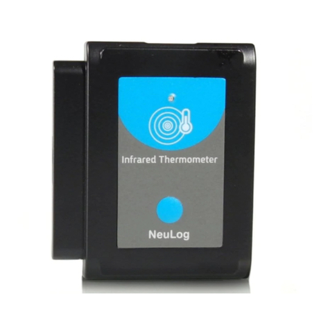
Operation with NeuLog Graphic Display Module (viewer)
Materials needed:
NUL-224 Flow Sensor
VIEW-101 Graphic Display Module
BAT-200 Battery Module
Procedure:
1. Connect the flow sensor to the left side of the viewer.
2. Connect the BAT-200 module to the right side of the viewer.
3. The VIEW-101 will auto detect the sensor and you will see it appear on the left
side of the screen.
4. Once the sensor appears it will be monitoring data in real time.
5. To run an experiment and collect data press the run icon (little green person).
Off-line experiments
(Off-line experiments are when you do not have a sensor connected directly to a
computer, tablet, smartphone, or NeuLog viewer).
Materials needed:
NUL-224 Flow Sensor
BAT-200 Battery Module
NEULOG FLOW LOGGER SENSOR GUIDE
Materials needed to configure your offline experiment:
USB-200 Module, WIFI-201 Module or VIEW-101 Module
USB to mini USB cable (included with the USB-200 module)
Procedure:
1. To determine the experiment settings, first connect to your chosen device (PC,
Mac, tablet, smart device) and click on the “Off-line experiment” icon after the
sensor search has ended. (For more information on how to change the
experiment settings, view the quick start procedure section for your chosen
device in this document.)
2. Connect the flow sensor directly to the left side of a charged BAT-200 module.
3. When ready to collect data press the “Start/Stop” button on the flow sensor; a
red light will turn on for the duration of the experiment.
4. After the experiment has concluded (the “Start/Stop” button is pressed again or
the data collection period ends) connect the sensor to your chosen device (you
can find full instructions in each device’s quick start procedure section).
5. Open the NeuLog application.
6. Click the “Off-line experiment” icon.
7. Click the “Load data from sensors” icon.
8. Select which experimental data to upload (5 experimental runs can be stored at
one time on the NUL-224 flow sensor).
Restoring sensor’s factory default settings:
Procedure:
1. Connect the USB-200 to a PC, Mac, tablet, or smart device.
2. Connect the flow sensor to a USB-200 module (they directly plug together).
3. Open the NeuLog application.
4. Click the “Tools” icon.
5. Click “Restore sensor’s factory defaults” on the menu.
Included with the sensor:
NeuLog NUL-224 Flow Sensor Guide (this document)
Flow sensor probe attached directly to the sensor's body by a durable rubber-
coated wire
Sensor's specifications
Range and operation modes
0 to 5 m/s
ADC resolution
Digital
Resolution
0.08 m/s
Max sample rate (S/sec)
100
Experiment Duration: 1 second to 31 days.
Sensor's features:
Fully digital data
Rugged plastic ergonomic case
Flow rate probe attached to the sensor's body by a durable rubber-coated wire
Push button switch for Start/Stop experiments in off line mode
LED indicator of experiment status (blinks while collecting data)
Pre-calibrated sensing equipment
Note: NeuLog products are intended for educational use.
Videos and experiment examples:
Videos, literature and other probes can be found at www.NeuLog.com.
In order to access the flow sensor's page, choose "Products" on the main menu
and then "Flow logger sensor".
In order to find the science experiments, choose "Experiments" on the main
menu of the NeuLog website, then choose "Physics", "Chemistry", "Biology" or
"Environmental Science".
Physics Experiment:
oFlowing Water (P-43)
NEULOG FLOW LOGGER SENSOR GUIDE
Technical background:
The philosophy behind NeuLog’s plug and play technology is based on each sensor’s
ability to store its own data due to an internal flash memory chip and micro-controller
in each plastic NeuLog body. This technology allows the sensor to collect and then
store the digital data in the correct scientific units (oC, oF, Lux, %, ppm, for example).
The sensor is pre-calibrated at the factory. The built-in software in the logger can be
upgraded for free at any time using the provided firmware update.
The flow sensor houses an internal water wheel; as liquid flows through the probe the
wheel rotates at the same velocity as the liquid's. The water wheel does not connect
directly to the walls of the sensor but instead, floats on a bearing to lower the friction of
the system allowing for the water wheel to take the velocity of the water passing
through it more accurately.
The water wheel shaft includes a magnet and the rotation is sensed by a Hall Effect
sensor, without any mechanical connection.
The flow is calculated by the internal controller that converts the rotation speed into
flow rate.
Maintenance and storage:
Never submerge the NeuLog sensor’s plastic body in any liquid.
Do not allow liquid into the flow sensor’s body.
After use, gently wipe away any foreign material from the flow sensor.
Store in a box at room temperature out of direct sunlight.
Warranty:
We promise to deliver our sensor free of defects in materials and workmanship. The
warranty is for a period of 3 years from the date of purchase and does not cover
damage of the product caused by improper use, abuse, or incorrect storage. Sensors
with a shelf life such as ion selective probes have a warranty of 1 year. Should you
need to act upon the warranty, please contact your distributor. Your sensor will be
repaired or replaced.
Thank you for using NeuLog!
Flexible, simple, fast, forward thinking.
W: www.neulog.com
E: info@neulog.com
A: 850 St Paul Street, Suite 15, Rochester, NY 14605
P: 1.866.553.8536
V11042014

Other NeuLog Accessories manuals

NeuLog NUL-205 User manual

NeuLog

NeuLog NUL-205 User manual

NeuLog NUL-240 User manual

NeuLog

NeuLog NUL-240 User manual

NeuLog NUL-202 User manual

NeuLog

NeuLog NUL-202 User manual

NeuLog NUL-216 User manual

NeuLog

NeuLog NUL-216 User manual

NeuLog NUL-219 User manual

NeuLog

NeuLog NUL-219 User manual

NeuLog NUL-223 User manual

NeuLog

NeuLog NUL-223 User manual

NeuLog UL-202 User manual

NeuLog

NeuLog UL-202 User manual

NeuLog NUL-227 User manual

NeuLog

NeuLog NUL-227 User manual

NeuLog NUL-212 User manual

NeuLog

NeuLog NUL-212 User manual

NeuLog NUL-209 User manual

NeuLog

NeuLog NUL-209 User manual

NeuLog NUL-214 User manual

NeuLog

NeuLog NUL-214 User manual

NeuLog NUL-221 User manual

NeuLog

NeuLog NUL-221 User manual

NeuLog NUL-206 User manual

NeuLog

NeuLog NUL-206 User manual

NeuLog NUL-215 User manual

NeuLog

NeuLog NUL-215 User manual

NeuLog NUL-237 User manual

NeuLog

NeuLog NUL-237 User manual

NeuLog NUL-225 User manual

NeuLog

NeuLog NUL-225 User manual

NeuLog NUL-216 User manual

NeuLog

NeuLog NUL-216 User manual

NeuLog NUL-210 User manual

NeuLog

NeuLog NUL-210 User manual

NeuLog NUL-211 User manual

NeuLog

NeuLog NUL-211 User manual

NeuLog NUL-245 User manual

NeuLog

NeuLog NUL-245 User manual

NeuLog NUL-233 User manual

NeuLog

NeuLog NUL-233 User manual

NeuLog NUL-236 User manual

NeuLog

NeuLog NUL-236 User manual

NeuLog NUL-209 User manual

NeuLog

NeuLog NUL-209 User manual

NeuLog NUL-202 User manual

NeuLog

NeuLog NUL-202 User manual

Popular Accessories manuals by other brands

Oway Segno Use and maintenance manual

Oway

Oway Segno Use and maintenance manual

Vaxcel T0278 Assembly and installation instructions

Vaxcel

Vaxcel T0278 Assembly and installation instructions

Philips 15719-8 Specifications

Philips

Philips 15719-8 Specifications

Siemens SIMATIC RTLS Device manual

Siemens

Siemens SIMATIC RTLS Device manual

Ritron 7 Series owner's manual

Ritron

Ritron 7 Series owner's manual

Omron E2EC - instruction sheet

Omron

Omron E2EC - instruction sheet

Allen-Bradley 871TM-M**NP18 Series user manual

Allen-Bradley

Allen-Bradley 871TM-M**NP18 Series user manual

IFM Electronic efector 500 PM2055 operating instructions

IFM Electronic

IFM Electronic efector 500 PM2055 operating instructions

Honeywell Sensepoint operating instructions

Honeywell

Honeywell Sensepoint operating instructions

Warner TCS-605-1 Installation instruction

Warner

Warner TCS-605-1 Installation instruction

PSI Woodworking PKCP80 Series quick start guide

PSI Woodworking

PSI Woodworking PKCP80 Series quick start guide

PCB Piezotronics ICP 137B24B Installation and operating manual

PCB Piezotronics

PCB Piezotronics ICP 137B24B Installation and operating manual

Kestrel Blue Ocean Megaphone manual

Kestrel

Kestrel Blue Ocean Megaphone manual

Leviton BR20I instruction sheet

Leviton

Leviton BR20I instruction sheet

Ados A100E instruction manual

Ados

Ados A100E instruction manual

Orno OR-DB-IL-128 Operating and instalation instructions

Orno

Orno OR-DB-IL-128 Operating and instalation instructions

Ironwood Electronics Grypper INSERTION AND REMOVAL GUIDE

Ironwood Electronics

Ironwood Electronics Grypper INSERTION AND REMOVAL GUIDE

Holland FWS1 Series owner's manual

Holland

Holland FWS1 Series owner's manual

manuals.online logo
manuals.online logoBrands
  • About & Mission
  • Contact us
  • Privacy Policy
  • Terms and Conditions

Copyright 2025 Manuals.Online. All Rights Reserved.