Neurosoft Neuro-ERG/V User manual

Technical Manual
Neuro-ERG/V
Veterinary Digital ERG System
TM006.04.001.000
(14.06.2019)

Neurosoft © 2020
5, Voronin str., Ivanovo, 153032, Russia
P.O. Box 10, Ivanovo, 153000, Russia
Phone: +7 (4932) 24-04-34; +7 (4932) 95-99-99 Fax: +7 (4932) 24-04-35
E-mail: info@neurosoft.com Internet: www.neurosoft.com

3
Contents
Introduction............................................................................................................... 4
Important Safety Instructions .................................................................................. 5
Intended Use....................................................................................................... 5
General Description............................................................................................. 5
Contraindications................................................................................................. 6
Possible Side Effects........................................................................................... 6
1. Description......................................................................................................... 7
1.1. Main Specifications....................................................................................... 7
1.2. Principle of Operation ................................................................................. 10
1.3. Connectors and Indicators.......................................................................... 12
1.4. Synchronization with Stimulators of Third-party Manufacturers................... 14
1.5. Synchronization with Neuro-MEP.NET Software......................................... 15
1.6. Labeling...................................................................................................... 17
2. Assembly and Installation............................................................................... 19
2.1. Requirements to Personnel ........................................................................ 19
2.2. Room Selection and Placement.................................................................. 19
2.3. Unpacking and Check of Delivery Set......................................................... 22
2.4. System Assembly and Connection.............................................................. 22
3. Proper use........................................................................................................ 24
3.1. Safety Measures......................................................................................... 24
3.2. Getting Ready............................................................................................. 24
3.3. Troubleshooting.......................................................................................... 25
3.4. Getting Started ........................................................................................... 28
3.5. Actions in Emergency................................................................................. 28
4. Maintenance..................................................................................................... 29
4.1. General Requirements................................................................................ 29
4.2. User Maintenance....................................................................................... 29
4.3. Disinfection................................................................................................. 29
5. Current Repair ................................................................................................. 30
5.1. General Requirements................................................................................ 30
5.2. Cables and Adapters .................................................................................. 30
5.3. Computer Interface Cable (USB Cable)...................................................... 30
5.4. LED Goggles.............................................................................................. 31
5.5. LED Penlights............................................................................................. 32
5.6. Mini-Ganzfeld Stimulator............................................................................. 32
6. Disposal ........................................................................................................... 33
7. Bullion Content Data ....................................................................................... 33
8. Delivery Set and Package Data....................................................................... 33
9. Warranty........................................................................................................... 34
10. Reclamation..................................................................................................... 35
Annex 1. Delivery Set ............................................................................................. 36
Annex 2. Electromagnetic Emissions and Immunity............................................ 38

Neuro-ERG/V (Technical Manual)
4
Introduction
This technical manual (hereinafter referred to as "the manual") is the combined docu-
ment describing operation and maintenance of the Neuro-ERG/V veterinary digital
ERG system (hereinafter referred to as "the system").
The document certifies technical parameters of the system, which are guaranteed by
the manufacturer.
Do not start working with the system before you have
read this document!
You can send your responses and recommendations to the following address:
P.O. Box 10, Ivanovo, 153000, Russia
or by e-mail:
help@neurosoft.com
You can find additional information about Neurosoft products on our website:
www.neurosoft.com
or ask questions by phone:
+7 (4932) 59-21-12; +7 (4932) 24-04-37 (Service Center)
+7 (4932) 24-04-34; +7 (4932) 95-99-99
You can also contact the Authorized European Representative of Neurosoft,
SAS Neuromed Company (Mr. Benjamin Scholl):
360 avenue du Clapier
ZAС du Couquiou
84320 Entraigues sur-la-Sorgue
France
Phone: +33 621-304-580
E-mail: info@neurosoft-france.com
In the USA, please, contact
Diagnus LLC
5 Larson Avenue, Smithtown, NY 11787 USA
+1-(800)-528-0940
https://www.diagnus.us
E-mail: info@diagnus.us

Important Safety Instructions
5
Important Safety Instructions
Intended Use
The Neuro-ERG/V system is intended to perform electroretinography (ERG) tests and
studies of flash visual evoked potentials (FVEPs).
The system can be used in veterinary hospitals and experimental laboratories of re-
search institutions to study:
functional state of animal brain;
optic tract of animals.
General Description
The system is intended for veterinary use only!
The Neuro-ERG/V system is used to:
evaluate the functions of retina in animals with cataracts and ocular media opacity;
evaluate retinal function in animals with vision loss/visual impairment;
evaluate retinal functions with altered, incomplete, missing pupil response to red
light during normal response to blue light, and also if it is impossible to evaluate the
response to light (atrophy of iris, miosis);
diagnose specific retinal pathologies (cone degeneration, progressive retinal atro-
phy, etc.) in animals with typical disease history and ophthalmoscopic findings;
make a differential diagnosis of neurological causes of vision loss from retinal pa-
thology (the technique of visual evoked potentials is also used);
detect the initial functional changes in retina that precede the clinical manifestations
of the disease;
control the progress of the pathological process and the effectiveness of treatment,
determine the prognosis of the disease.
Features:
1-4 channel acquisition of signals in any unshielded room;
Acquisition of flash visual evoked potentials;

Neuro-ERG/V (Technical Manual)
6
Electroretinography (ERG);
Generation of examination report;
Review, storage and printing of the recorded curves, results of their analysis and
examination reports.
Contraindications
The electroretinography (ERG) is not recommended if the examined animal has:
signs of acute inflammatory and/or allergic disease of cornea, conjunctiva, eyelid, or
traumatic injury of eyeball;
contraindications for sedation.
Possible Side Effects
Usually, the side effects are not observed. However, the following can occur very rare-
ly:
allergic reactions to the components of agents used for exam preparation or to the
components of used electrodes;
transient visual impairment during high-intensity long-term visual stimulation;
small hemorrhages in the places where needle electrodes are applied.

Description
7
1. Description
1.1. Main Specifications
Table 1. Main Specifications
Parameters
Values
Amplifier Channels
Number of channels
4
Sampling rate
200 Hz –40 (160) kHz
Voltage range
20 µV 50 mV
Ratio error of voltage measurement:
in the band from 20 up to 100 µV
in the band from 0.1 up to 50 mV
±15%
±5%
EP voltage range at averaging
0.1400 µV
Ratio error of EP voltage measurement at
averaging
±10%
Common-mode rejection
not less than 100 dB
Input noise level, rms
not more than 0.5 µV
Input impedance
not less than 200/1000MΩ
Input capacitance of amplifiers
not more than 25/22 pF
Patient leakage current
not more than 0.1 µA
Bandpass flatness in the band:
from 0.02 up to 0.05 Hz and from 5 up to
10 kHz
from 0.05 Hz up to 5 kHz
from –30 up to +5%
from –10 up to +5%
High pass filter
0.02, 0.05, 0.1, 0.2, 0.3, 0.5, 1, 2, 3, 5, 10, 20,
30, 50, 100, 200, 300, 500, 1000, 2000, 3000 Hz
Low pass filter
10, 20, 35, 50, 75, 100, 150, 200, 300, 500 Hz;
1, 2, 3, 5, 10 kHz
Sensitivity
0.05, 0.075, 0.1, 0.15, 0.2, 0.25, 0.4, 0.5, 0.75,
1, 1.5, 2, 2.5, 4, 5, 7.5, 10, 15, 20, 25, 40, 50,
75, 100, 150, 200, 250, 400, 500, 750 µV/div.;
1, 1.5, 2, 2.5, 4, 5, 7.5, 10, 15, 20, 25, 40,
50 mV/div.
Relative error of sensitivity
±5%
Sweep speed
0.1, 0.15, 0.2, 0.25, 0.4, 0.5, 0.75, 1, 1.5, 2, 2.5,
4, 5, 7.5, 10, 15, 20, 25, 40, 50, 75, 100, 150,
200, 250, 400 ms/div; 0.5, 0.75, 1, 1.5, 2 s/div.
Relative error of sweep speed
±1%
Suppression ratio of power frequency by notch
filter
not less than 40 dB

Neuro-ERG/V (Technical Manual)
8
Table 1. Continued
Parameters
Values
Visual Stimulator
Maximum brightness of:
LED goggles
mini-ganzfeld stimulator
(1100 ± 110) cd/m2
(1500 ± 150) cd/m2
Maximum brightness power of:
white penlight
red penlight
blue penlight
green penlight
(0.2 ± 0.05) cd
(0.3 ± 0.075) cd
(0.15 ± 0.0375) cd
(0.2 ± 0.05) cd
Brightness control range
-3…0 log units
Stimulus duration
0.05–1500 ms
Relative deviation of stimulus duration
within ±10%
Stimulus frequency
0.01–100 Hz
Relative deviation of stimulus frequency
±1%
Left / right / two-sided stimulation when using LED
goggles
available
General Parameters and Characteristics
Interface
USB
Supply voltage:
electronic unit
desktop PC-based system
notebook PC-based system
5 V DC
220/230 V AC (50 Hz)
110 V AC (60 Hz)
220/230 V AC (50 Hz)
110 V AC (60 Hz)/int. battery
Dimensions:
amplifier unit
auditory-visual stimulator unit
190×140×50 mm
155×105×40 mm
Weight:
amplifier unit
auditory-visual stimulator unit
not more than 1 kg
not more than 0.5 kg
Safety
BF type
Transportation Conditions
Temperature
-25 up to +60°C
Humidity
from 20 to 95% non-condensing
Atmospheric pressure
from 70 kPa
Storage Conditions
Temperature
+5 up to +40°C
Humidity
from 30 to 85% non-condensing
Atmospheric pressure
70-106 kPa

Description
9
Table 1. Continued
Parameters
Values
Operation Conditions
Temperature
+10 up to +35°C
Humidity
from 30 to 85% non-condensing
Atmospheric pressure
70-106 kPa
Safety and Electromagnetic Compatibility
Electromagnetic compatibility (EMC) is provided by conformance to IEC 60601-1-2-
2014 (EN 60601-1-2:2015) requirements.
The system is intended for operation in electromagnetic environment, which special
features are specified in Annex 2.
Portable and mobile RF communication equipment can affect the system operation.
The use of equipment not listed in Table 5 of this technical manual may result in in-
creased emission and system decreased immunity.
As for safety, the system satisfies IEC 60601-1:2012 (AAMI/ANSI ES 60601-
1:2005/(R2012) and A1:2012 and A2:2010/(R)2012, EN 60601-1:2006/A1:2013) and
IEC 60601-2-40:2016 (EN 60601-2-40:2017). The electronic unit is supplied by regu-
lated power supply through USB interface, it has double isolation and BF type applied
parts according to IEC 60601-1:2012 (AAMI/ANSI ES 60601-1:2005/(R2012) and
A1:2012 and A2:2010/(R)2012, EN 60601-1:2006/A1:2013).

Neuro-ERG/V (Technical Manual)
10
1.2. Principle of Operation
The operation of the system is based on the recording and input of biopotentials to
computer to perform the analysis of their electrical activity, including the response to
stimulus.
The block diagram of the system is shown in Fig. 1.
Fig. 1. Block diagram of system.
The function of amplification and recording of biopotentials is performed by
the amplifier unit.
The biopotentials from the electrodes are delivered to the amplifiers of the amplifier
unit where they are amplified, then quantized with the use of the analog-digital con-
verter (ADC) and are transferred to the microcontroller (MC) via 4000 V galvanic isola-
tion. The microcontroller provides the connection with the computer via USB and
the transfer of the digitized data to the computer (PC). Besides, it controls the amplifi-
ers and ADC operation via 4000 V galvanic isolation.
The power supply of the galvanically isolated part of the amplifier unit, i.e. the amplifi-
er module is done via the galvanically isolated direct-voltage transducer of the supply
unit (SU).
The microcontroller of the unit provides the connection between the digital signal pro-
cessor (DSP) of the module and the computer via USB. Also, the MC generates
the amplitude with the use of the pulse-wide modulator (PWM) and the pulse duration
on the photic stimulator with the use of the switches. DSP generates the signal of the

Description
11
sound stimulator in a discrete form, which is transformed by the digital-analog con-
verter to the analog form, amplified by the sound amplifier and is supplied to the audi-
tory stimulator. DSP also generates the visual signal which is transferred to the visual
stimulator via the visual amplifier.
The photic stimulator is LED goggles with a set of super-power LEDs for the separate
stimulation of the left and right eye.
All the units are attached to the computer via USB-hub.
The system operates under control of PC (IBM PC type) with the mouse, keyboard,
laser or jet printer and installed licensed Windows 8/10 operational system.
Signal processing, displaying and presentation in different modes after mathematical
analysis, then storing of the initial data on the hard disk, exam report generation and
printing is done using PC.

Neuro-ERG/V (Technical Manual)
12
1.3. Connectors and Indicators
The front and side panels of the amplifier unit are shown in Fig. 2 and Fig. 3.
On the front panel of the amplifier unit there are the touch-proof and DIN-connectors
to attach the electrodes and operation indicator (Fig. 2). The channel numbers are
marked with Arabic figures “1”, “2”, “3” and “4”. The operation indicator glows yellow if
the unit is connected to the computer and it glows green at the signal recording during
the program operation.
Fig. 2. Front panel of amplifier unit.

Description
13
On the top side panel of the amplifier unit there are USB cable for connection to PC
and the trigger input socket to connect the stimulators of third-party manufacturers
(Fig. 3).
Fig. 3. Side panel of amplifier unit.
The front and rear panels of auditory-visual stimulator unit are shown in Fig. 4 and
Fig. 5.
On the front panel of the auditory-visual stimulator unit there are the connectors for
visual stimulator (LED goggles or mini-ganzfeld), multi-colored penlights and LED op-
eration indicator (Fig. 4). The operation indicator glows yellow when the electronic unit
is connected to PC and it glows green when the signal is recorded during the perfor-
mance of visual or auditory stimulation.
Fig. 4. Front panel of auditory-visual stimulator unit.

Neuro-ERG/V (Technical Manual)
14
On the rear panel of the auditory-visual stimulator unit there are the connector for
USB cable (for connection to PC), connector for reversal pattern monitor (not for vet-
erinary use) and trigger output socket (Fig. 5).
Fig. 5. The rear panel of the auditory-visual stimulator unit.
The USB hub KM-7-2 can also be included in the delivery set of the system. The in-
formation about the functions of the connectors and indicators of USB hub and also its
operation is described in the corresponding technical manual.
1.4. Synchronization with Stimulators of Third-party
Manufacturers
The trigger input socket is used for synchronization of the amplifier with other devices.
It is located on the top side panel of the amplifier. The numbering of the socket pins is
shown in Fig. 6 and the functions of these pins are described in Table 2.
The devices attached to the trigger socket must have the protection class against
the electrical shock according to IEC 60601-1:2012 (AAMI/ANSI ES 60601-
1:2005/(R2012) and A1:2012 and A2:2010/(R)2012, EN 60601-1:2006/A1:2013).
Fig. 6. Numbering of socket pins (view from the case outside).
Description
15
Table 2. Functions of socket pins.
Pin number
Name
Function
3
+SYNC
Trigger signal input
4
0V
Common
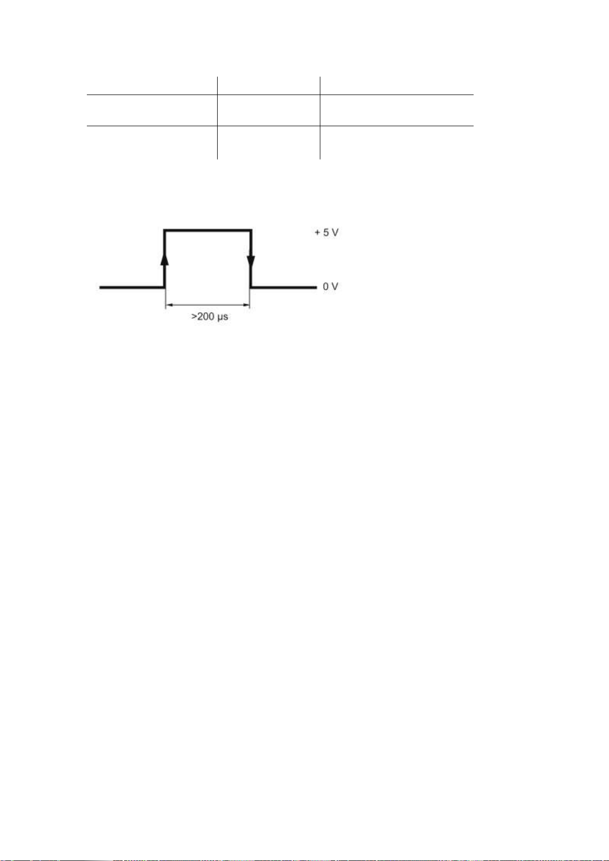
For the synchronization, apply positive TTL pulse on the + SYNC output in relation to
0 V (Fig. 7). The synchronization will occur by the pulse front with ±25 µs accuracy.
Fig. 7. Signal shape at +SYNC output in relation to 0 V.
To synchronize the auditory-visual stimulator with other devices, use the trigger output
socket located on the side panel of the unit. The numbering of the socket pins is the
same as on the amplifier.
When the trigger output is used with each stimulus generated by stimulators, negative
polarity pulse appears at the connector which fall corresponds to the beginning of the
stimulus.
The pulse duration at the trigger output is 2…5 µs.
1.5. Synchronization with Neuro-MEP.NET Software
The external stimulators connected to the trigger input must be used as follows:
1. Connect the external stimulator to the trigger input using a cable.
2. Switch on the external stimulator power supply.
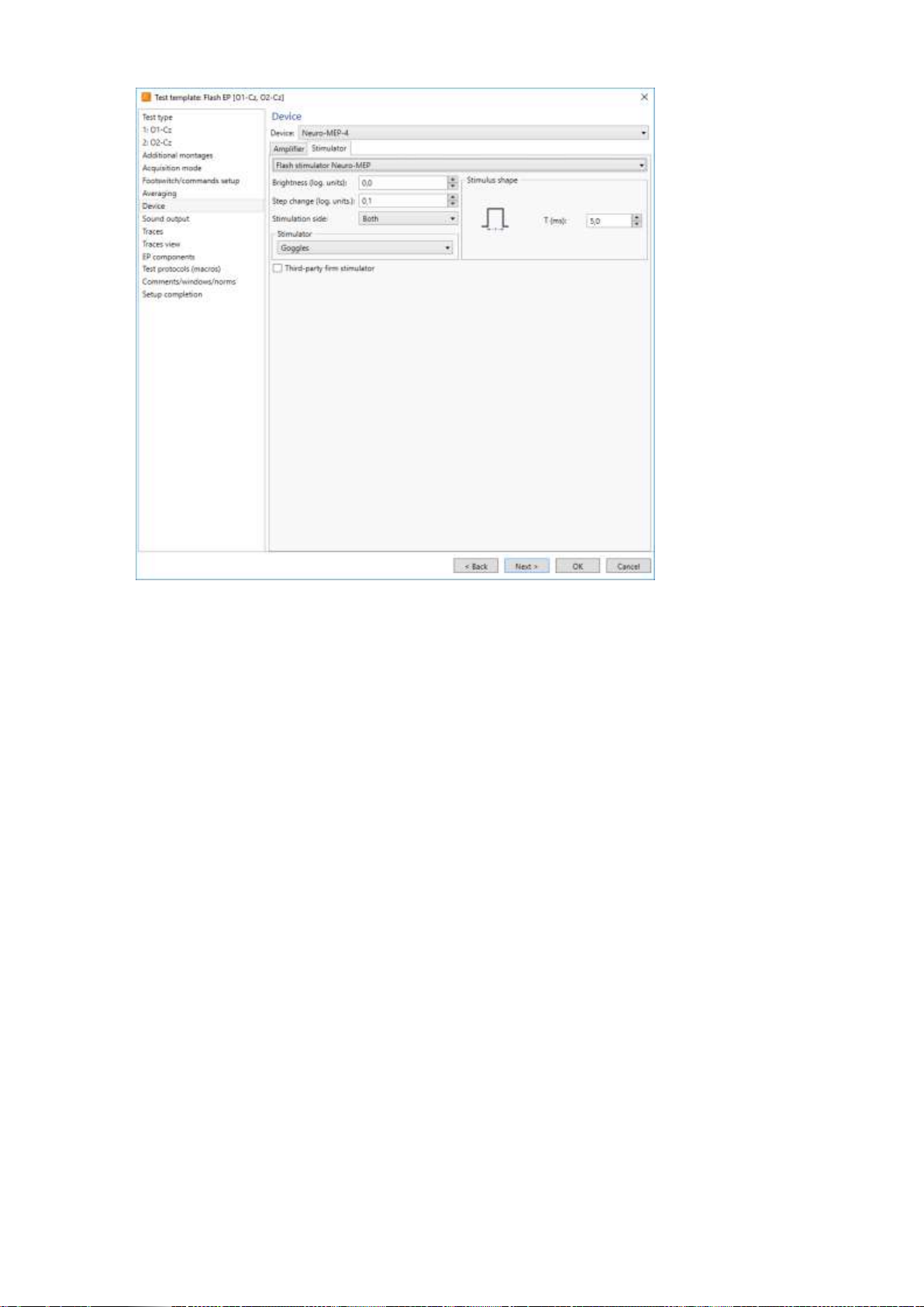
3. Run the Neuro-MEP.NET software, execute the Setup|Tests templates|Setup
menu command, select the required test template, press the Change button and
select the Third-party firm stimulator check box on the Hardware|Stimulator page
(Fig. 8). This step should be executed once for each template where the external
stimulator is planned to be used. If you do not want to change the template, cre-
ate the test and select the similar settings in it.
Neuro-ERG/V (Technical Manual)
16
Fig. 8. The acquisition start window from external stimulator.
4. In the stimulation settings it is recommended to set those stimulus parameters
which the external stimulator has as these particular values are saved together
with the trace and taken into analysis.
5. Run the Acquisition|Acquisition/stimulus menu command. The device goes to the
external stimulus standby mode. If this menu command is not executed, any
stimuli from the external stimulator are ignored.
6. Start stimulation from the external stimulator.
In other aspects the signal acquisition does not differ from the one described in
the corresponding chapters of the user manual.
The external stimulators connected to the trigger output must be used as follows:
1. Connect the external stimulator to the trigger output using a cable.
2. Switch on the external stimulator power supply.
3. Run Neuro-MEP.NET software.
4. In the stimulation settings it is recommended to set those stimulus parameters
which the external stimulator has as these particular values are saved together
with the trace and taken into analysis.
Description
17
The Third-party firm stimulator check box (Fig. 8) is NOT checked!
In other aspects the signal acquisition does not differ from the one described in the
corresponding chapters of the user manual.
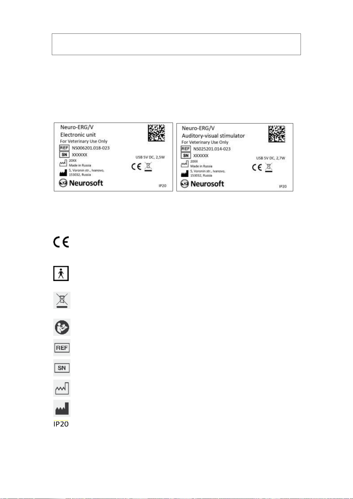
1.6. Labeling
The example of labeling of electronic units is shown in Fig. 9.
Fig. 9. Labeling.
Interpretation of symbols on electronic units:
mark of conformance to 2014/30/EU of the European Parliament
and of the Council of 26 February 2014 on the harmonization of the
laws of the Member States relating to electromagnetic compatibility.
–applied parts of BF type according to IEC 60601-1:2012 (AAMI/ANSI
ES 60601-1:2005/(R2012) and A1:2012 and A2:2010/(R)2012, EN
60601-1:2006/A1:2013). This symbol is on the front panel of the
amplifier and audio-video stimulator units.
–mark of conformance to 2012/19/EC “On waste electrical and
electronic equipment (WEEE)” directive.
–attention: consult operational documentation. This symbol is on the
front panel of the amplifier and audio-video stimulator units.
–number according to catalogue by ISO 15223-1.
serial number by ISO 15223-1.
manufacturing date by ISO 15223-1.
manufacturer’s name and address by ISO 15223-1.
ingress protection according to IEC (EN) 60529.

Neuro-ERG/V (Technical Manual)
18
The equipment is identified with the GS1-128 barcode integrated to the barcode in
DataMatrix format (Fig. 10).
Fig. 10. DataMatrix barcode.
Data Matrix is a two-dimensional matrix barcode, consisting of black and white “cells”
or modules of different brightness arranged in either a square or rectangular pattern.
The DataMatrix barcode is described in ISO/IEC 16022:2006 standard.
To decode the data on device, DataMatrix barcode can be read quickly by a barcode
reader or by the smartphone camera as a two-dimensional image.

Assembly and Installation
19
2. Assembly and Installation
2.1. Requirements to Personnel
The assembly and installation of the system should be carried out by a person who is
empowered by the manufacturer or technical personnel of the medical institution
which is going to use it. Remember, that the accuracy of system mounting defines the
safety and quality of its operation. Further mounting and setting requirements which
define the product safety will be marked by bold font in the text.
2.2. Room Selection and Placement
Before installation of the system, select the place for it taking into consideration the
power wiring and protective ground in the room. Please, read the following require-
ments and recommendations:
Requirements concerning the room selection and equipment placement:
The recommended distance from the electronic unit to the nearest electric mains is
not less than 3 meters.
The location of electronic unit in the immediate vicinity (less than 5 meters) with
short-wave or microwave therapeutic equipment is not permitted (it can lead to its
unstable operation).
It is recommended to place the electronic unit on the maximum possible distance
from power cables, switchboards, and different powerful electrical devices which
can emit electromagnetic fields of mains frequency.
The animal environment (within 1.5 meters) should contain only the electronic
units being the medical device with the required safety level. As the computer
equipment safety level is not sufficient for use in the animal environment, it is
necessary to exclude the possibility of animal touching the metal parts of the
computer equipment cases and the simultaneous contact of these parts and
animal's body by the personnel. The computer equipment used in the system
should correspond to IEC 60601-1:2012 (AAMI/ANSI ES 60601-1:2005/(R2012)
and A1:2012 and A2:2010/(R)2012, EN 60601-1:2006/A1:2013 or be connected
via the isolation transformer (specialized power supply unit –for notebook
PC) corresponding to abovementioned requirements.
Requirements to mains:
Do not use electric mains where the neutral conductor and protective ground
are combined. It is strongly prohibited.
The use of multi-socket electric mains extender without additional protective
actions is prohibited. The fact is that the probable break of the circuit of the

Neuro-ERG/V (Technical Manual)
20
protective ground of the multi-socket electric mains extender can lead to
summation of leakage current in all connected units on their metal parts to
dangerous values.
Before the system setting, the electrician must check the quality of standard
tripolar sockets and the integrity of the protective ground circuit.
In case the system components are connected to several tripolar sockets,
make sure they are grounded to one and the same protective ground circuit.
Otherwise, there is a danger of several tens of amperes compensating current
leakage through the system connecting cables that leads to the equipment
break-down.
Requirements for PC connection to local area network (LAN):
To avoid the electrical shock, connect PC to local area network (LAN) according
to 10/100/1000-BaseT-Ethernet standard only if LAN complies with safety re-
quirements to ME equipment IEC 60601-1:2012 (AAMI/ANSI ES 60601-
1:2005/(R2012) and A1:2012 and A2:2010/(R)2012, EN 60601-1:2006/A1:2013) or
using the isolation transformer that conforms to the abovementioned require-
ments.
The variants of equipment placement when connected to the desktop or notebook PC
are shown below (see Fig. 11, Fig. 12).
Fig. 11. Placement of equipment connected to desktop PC.
Table of contents
Popular Pet Care Product manuals by other brands

Petsafe
Petsafe PBC19-16370 product manual

AERTEK
AERTEK AT-216D owner's manual

Innotek
Innotek Spray Bark Control operating guide

Radio System Corporation
Radio System Corporation PetSafe SNS-BK-C Operating and training guide

Petrainer
Petrainer CVJC-G340-2GEN quick start guide

SHOR-LINE
SHOR-LINE CAT CONDO Customer and Product Information

Garmin
Garmin Delta Inbounds owner's manual

Canine Innovations
Canine Innovations Pet Convincer II user guide

Martin Sellier
Martin Sellier Dynavet Effitek 1ONE Instructions for use

JUWEL Aquarium
JUWEL Aquarium SmartFeed instruction manual

Zoovilla
Zoovilla PTF0093920110 manual

FERRANTI
FERRANTI COLLIE Assembly manual


