Newland NL-PP60 User manual


Index
1.Manual introduction.......................................................................................................................3
2.Getting started................................................................................................................................3
2.1 Introduction.........................................................................................................................3
2.2 comprehend NL-PP60.........................................................................................................3
2.2.1 Unpacking................................................................................................................3
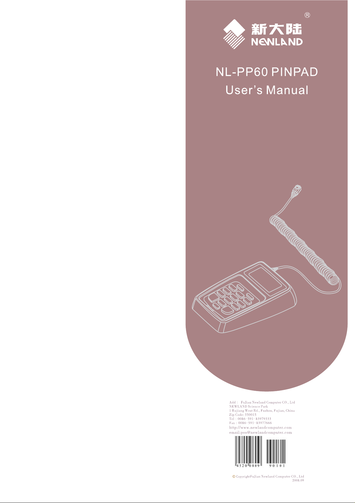
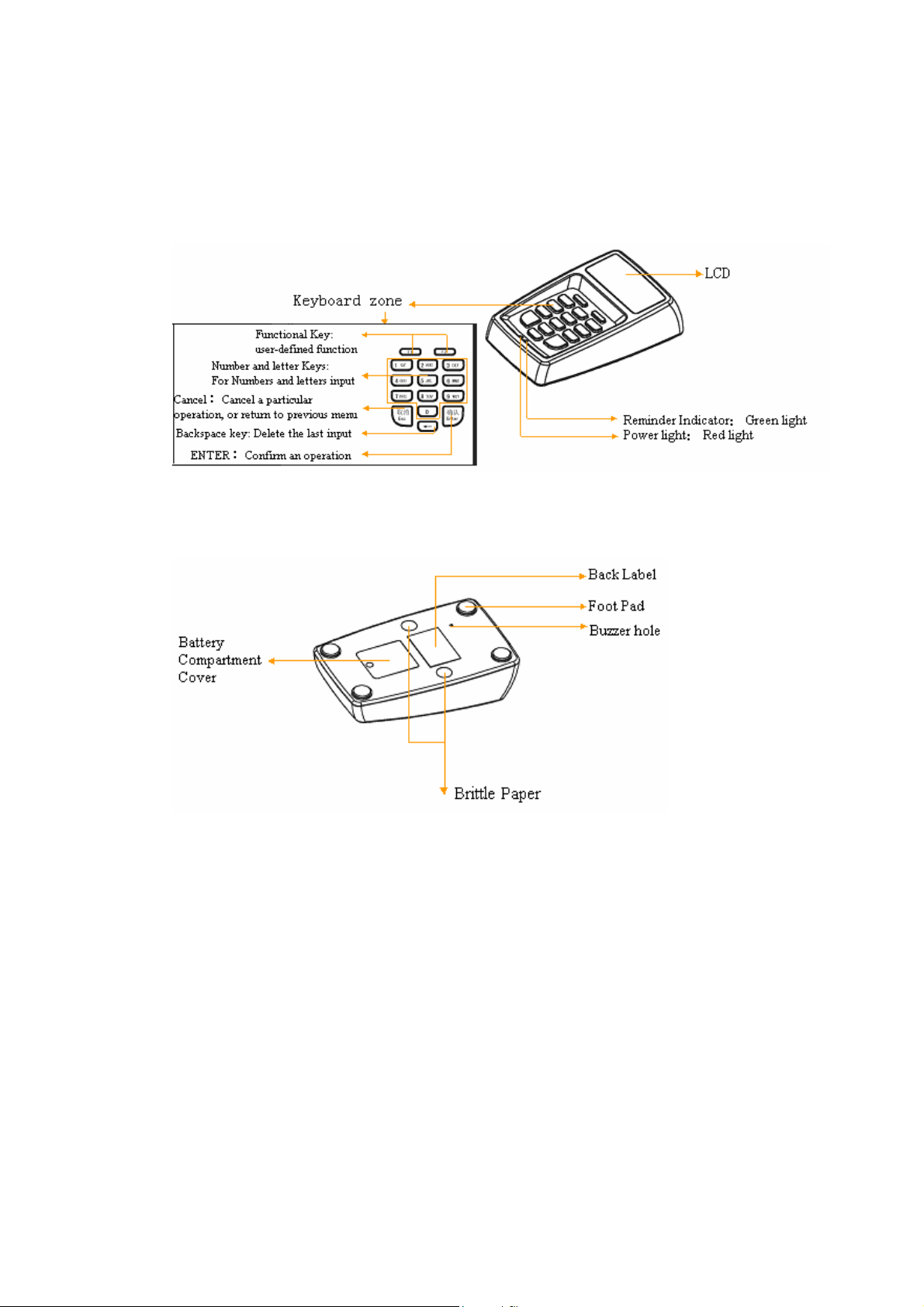
2.2.2 Appearance...............................................................................................................4
2.2.3 NL-PP60 detailed description of functions..............................................................4
2.3 Each interface’s function and PIN definition......................................................................5
2.3.1 PP60 configuration table..........................................................................................5
2.3.2 Spiral Cable for the PINPAD ...................................................................................6
2.3.3 Device connection....................................................................................................8
2.4 How to use the PINPAD.....................................................................................................9
3.Operation and Prompts.................................................................................................................10
3.1 startup screen.....................................................................................................................10
3.2 LED indicator light and LCD backlight control................................................................10
3.3 Enter Password..................................................................................................................10
3.4 The input of Authentication KEY .....................................................................................11
3.5 The input of Master KEY/Fixed KEY/initial DUKPT KEY.............................................12
3.6 PIN Entry ..........................................................................................................................13
3.7 Attack Warning Message..................................................................................................14
4.NL-PP60 command interfaces and setting...................................................................................15
4.1 Reset PINPAD...................................................................................................................15
4.1.1Command Format ...................................................................................................15
4.1.2 Command Description ...........................................................................................16
4.2 Choosing directory Directory............................................................................................16
4.2.1 Command Format...................................................................................................16
4.2.2 Command Description ...........................................................................................17
4.3 UID setting........................................................................................................................17
4.3.1 Command Interface................................................................................................17
4.3.2Command Description ............................................................................................18
4.4 PSW Setting......................................................................................................................18
4.4.1 Command Interface................................................................................................18
4.4.2 Command Description ...........................................................................................19
4.5 Random Number...............................................................................................................20
4.5.1 Command Format...................................................................................................20
4.5.2 Command Description ...........................................................................................20
4.6 Download Master KEY/authentication KEY/Fixed KEY/DUKPT KEY.........................21
4.6.1 Command format ...................................................................................................21
4.6.2 Command Description ...........................................................................................25
4.7 Issue NL-PP66 ..................................................................................................................27
4.7.1Command Format ...................................................................................................27
4.7.2 Command Description ...........................................................................................28

4.8 Read the NL-PP60 hardware and software version number .............................................29
4.8.1Command Format ...................................................................................................29
4.8.2Command Description ............................................................................................30
4.9 Distribute PIN encrypt/MAC encryption’s work KEY.....................................................30
4.9.1 Command Format...................................................................................................30
4.9.2 Command Description ...........................................................................................31
4.10 Setting KSN of DUPKT KEY.........................................................................................32
4.10.1 Command format .................................................................................................32
4.10.2 Command Description .........................................................................................33
4.11 Read the current KSN .....................................................................................................33
4.11.1Command Format..................................................................................................33
4.11.2 Command Description..........................................................................................34
4.12 Choose PIN Encryption Key...........................................................................................34
4.12.1 Command Format.................................................................................................34
4.12.2 Command Description .........................................................................................36
4.13 PIN Entry Method One (User entered password is encrypted using ANSI X9.8 standard)
36
4.13.1 Command Format.................................................................................................36
4.13.2 Command Description .........................................................................................37
4.14 PIN Entry Method Two (New account user entered password is encrypted using ANSI
X9.8 Standard) ........................................................................................................................39
4.14.1 Command Format.................................................................................................39
4.14.2 Command Description .........................................................................................40
4.15 Cancel PIN Entry............................................................................................................41
4.15.1 Command Format.................................................................................................41
4.15.2 Command Description .........................................................................................42
4.16 MAC Encryption.............................................................................................................42
4.16.1 Command Format.................................................................................................42
4.16.2 Command Description .........................................................................................43
4.17 Operational Record Reading...........................................................................................44
4.17.1 Command Format.................................................................................................44
4.17.2 Command Description .........................................................................................45
5.Attentions.....................................................................................................................................46
5.1 Daily usageAttentions......................................................................................................46
5.2 Maintenance Instruction....................................................................................................46
5.3 Security and Attack Identification.....................................................................................46
5.3.1 Appearance Inspection...........................................................................................46
5.3.2 Brittle paper Identification.....................................................................................47
6.Trouble Shooting .........................................................................................................................48

1.Manual introduction
NL-PP60 is a KEYPINPADPINPAD that is approved by PCI SSC appointed lab. It is good at
innovative design, superior performance, compact and lightweight, and with high information
security..
In order to meet the information security requirements for PIN Entry Device from the
financial industry, Newland NL-PP660 KEYPINPAD uses new design that prevents explore
and attack. Special configuration and physical defense design protects sensitive information
from being stolen or changed. It adopts the MK/SK KEY management system, supports
PIN Entry and MAC encryption.
This manual introduces how to use the NL-PP60 correctly, and also provide information to
third-party developers for secondary software development.
2.Getting started
2.1 Introduction
NL-PP60 is a PIN Entry Device; use the RS232 communication protocol, security handler,
theft protection crust and real time burglarproof mechanism. It adopts the MK/SK KEY
management system, support PIN input and MAC Encryption.
This chapter will introduce NL-PP60 from unpacking to detailed operation. It includes
housing, principle, and detailed description of each function, each PIN definition, and
function of each interface, and other relevant settings.
2.2 comprehend NL-PP60
2.2.1 Unpacking
Open the packing; get the PINPAD and accessories. Check if the appearance is intact. If any
damage happened during the transport, please contact your hardware supplier, and retain the
packaging. Make sure using the original package to return the damaged product, to ensure
your after-sale rights.

2.2.2 Appearance
The front side description
The back side description
2.2.3 NL-PP60 detailed description of functions
Main features:
zPCI PED Approval
zCompactAppearance, cabinet modeling, smooth lining, comfort handling
z32 bit ARM core CPU, large-capacity memory
zMultiple security systems ensuring KEY safety;
Support DES/TDES, AES128-256(extensible), SHA-1, SHA-256(extensible), RSA,
DSA (extensible); support ANSI X9.8/ISO9564, ANSI X9.24, ANSI X9.52, ISO11568,
ISO13491 standard
zKEY management: Fixed, MK/SK, DUKPT (extensible)
zSupport RJ11 or PS2 interface, serial communication

Technical specifications
Specifications Parameters description
CPU 32-bit, ARM core, RISC command
Storage 32KB ROM Memory、256KB EEPROM; 100KB internal RAM;
Communication RS232 serial port, 9600bps, (1.8.1, No-verification)
Interface RJ11, PS2(optional)
Power DC 4.5V ~DC5.5V;200mA(Max)
Display 122*32 LCD. LED backlight
Keyboard 10 letter/number keys, five functional keys
Dimension 141mm(L)×84.5mm(W)×38mm(H)
Weight 400g
Temperature: 0℃-40℃
Operating
environmental Humidity: 30%-90% (Non-condensing)
Temperature:-250℃~55℃
Environmental Storage
environmental Humidity: 20%-95% (Non-condensing)
2.3 Each interface’s function and PIN definition
2.3.1 PP60 configuration table
model PS/2 RJ11 remark
PP60A ◆
PP60B ◆
Communication interface uses RS232 protocol.
PS/2 or RJ11 interfaces. Other type of interface
can be made as desired.
The interface provides both communication and power supply, read below for detailed
information。

2.3.2 Spiral Cable for the PINPAD
One end of the cable connects to the PINPAD, and the other end head connects to POS/PC/or
other terminal. Please see the figure below:
一、The POS End (two kinds of interface)
a) PS2 interface
①②
③④
⑤⑥
NL-PP60 spiral cable PS2 interface (male connector)
PIN definition:
①:RXD ②:NC ③:GND ④:5V ⑤:TXD ⑥:NC
b) RJ11 interface
TOP
FRONT
NL-PP60 spiral cable RJ11 interface (male connector)

PIN definition
1:TXD 2:VCC 3:NC 4:NC 5:GND 6:RXD
二、The PINPAD End
1、The lining order of the spiral cable’s PINPAD End (1.0 socket):
Color definition:
TXD:red
VCC:green
GND:black
GND:black
RXD:white
The serial port definition above is for the PINPAD End, for example, RXD means the
receiving end of the PINPAD.
2、The spiral cable connected with the PCB board of the PINPAD

2.3.3 Device connection
Please connect the PINPAD to specified devices only. Connecting with unlicensed device may
have potential safety hazard, and may void your warrant.
一、PP60A connecting with NL-8200 POS
8200POS
PP60A
二、PP60B connecting with NL-8510 POS
8510POS
PP60B

2.4 How to use the PINPAD
The PINPAD cannot operate alone; it must be connected to the a associated device. The
spiral cable is used for connecting with a device providing communication and power supply.
The device to be connected to can be POS, PC, and other terminals as long as they are in
compliance with the PS2/RJ11 interface requirements described in chapter 2.3.2.
1)、Prepare a POS
2)、Connect PINPAD to POS using the spiral cable.
3)、Turn on the POS
4)、There is PINPAD’SLCD, which displays the following information
NL-PP60 001004
NEWLAND CO,LTD.
5)、If the left sideLED on the PINPAD is redthen it means the power is connected
6)、If the PINPAD is waiting for keyboard input, the right side green LED will
turn on.

3.Operation and Prompts
3.1 startup screen
3.2 LED indicator light and LCD backlight control
When using the keyboard, for example: entering password, entering Key Component, and
entering PIN. Before entering the operational interface, both of the LED indicator and LCD
backlight will turn on; when left the operational interface both lights will turn off.
3.3 Enter Password
The PINPAD is designed as a multiple users system. It provides up to 4 user directory based
on requirements. Each directory can be set with independent password, which is used for
controlling the key component entry of directory master KEY/fixed KEY/initial DUKPT
KEY/ Authentication KEY for that directory。
Each Key may generate 3 key components; the entry of each key component is controlled by
correspondent password, so 3 passwords are needed for key component entry. Passwords are
input by administrator manually from PINPAD’s keyboard; the screens are shown as below:
Enter Password 1 (the input of corresponding KEY component 1):
NL-PP60 001004
Input PSW1:
NEWLAND CO,LTD.
Enter Password 2 (the input of corresponding KEY component 2):
Input PSW2:

Enter Password 3 (the input of corresponding KEY component 3):
Input PSW3:
3.4 The input ofAuthentication KEY
Authentication key is set by administrator by entering key components from PINPAD’s
keyboard; no change is allowed after it is set. The entry of authentication key requires
correspond password validation. Please refer to chapter 3.3 for the password entry screens.
Once you passed the password validation, the screen for key component input will appear,
see the figure below:
Enter AuthKEY component 1:
Authkey compone
nt1:(32 Hex)
Enter AuthKEY component 2:
Authkey compone
nt2:(32 Hex)
Enter AuthKEY component 3:
Authkey compone
nt3:(32 Hex)
After all KEY components are entered, you will be asked to enter then again for
confirmation.
Input again:
(32 Hex)
Only if the two inputs are identical, the PINPAD will save the setting.

Keyboard guidance for Key Components input:
Enter the KEY component need to use the hex rules, so 16-byte KEY component needs
32 characters. Number keys, backspace (cancel entered character), Cancel Key (cancel
all entered characters), Enter (confirm the input) are available for KEY component
input.
The way of input A-F letter is: Press F2 to start the letter input mode, at this time, the
keys of 1-5 are respectively correspond to the letter A-F. For example, if you want to
enter letter A, firstly you press F2, then press 0. If you want to enter 1AB2, the press
order is “1, F2, 0, F2, 1, 2”. Press F1 to return to number input mode from letter input
mode.
3.5 The input of Master KEY/Fixed KEY/initial DUKPT
KEY
The input of Master KEY/Fixed KEY/initial DUKPT KEY is set by administrator by entering
key components from PINPAD’s keyboard. The entry of such keys requires correspond
password validation. Please refer to chapter 3.3 for the password entry screens.
Once you passed the password validation, the screen for key component input will appear,
see the figure below:
Enter KEY component 1
key component1:
(32 Hex)
Enter KEY component 2:
key component2:
(32 Hex)
Enter KEY component 3:
key component3:
(32 Hex)

After all KEY components are entered, you will be asked to enter then again for
confirmation.
Input again:
(32 Hex)
Only if the two inputs are identical, the PINPAD will save the setting.
For the keyboard guidance of KEY component input, please sees 3.4
3.6 PIN Entry
The screen for PIN Entry is shown below:
PLS Input PIN:
The entered PIN will be displayed in the second line as *
According to user defined input mode, we support the function of re-entering the PIN for
confirmation, see the figure below:
PLS Input PIN:
****
PLS Same again:
****
For PIN Entry, 0-9 number keys, backspace, cancel and enter keys are available.

3.7 Attack Warning Message
If PED detected a attack, its LCD will display the message below
Dangerxxxxxxxxx
xxxxxxxxxxxxxxx
xxxxxxxxxxxxxxxxxxxxxxxx is a 24 characters warning code; it is the important information
for the vendor to judge the attacking method. So if the warning message appeared, please
keep the PINPAD and wait for professional for analysis.

4.NL-PP60 command interfaces and setting
Command interface communication protocol:
The following protocol must be used for PINPAD to communicate with POS or other serial
port device:
Request To Send: The head of request [1byte] + data length [1 byte] + data […] + verification
bit [1 byte]
Responding To Send: The head of responding [1byte] + data length [1 byte] + data […] +
verification bit [1 byte
Or:
The head of responding [1byte] + data length [1 byte=0x01] + error
code [1byte] + verification bit [1 byte]
For normal responding, head of request and responding are the same; for wrong responding,
the head of responding is equal to the operation result of the head of request and 0X7F.
Data length is the length of data field.
Verification bit is all the XOR results from begin to end.
Command set and command format definition
4.1 Reset PINPAD
4.1.1Command Format
Sending data
CMD LEN EDC
0xd5 0x00 Verification
Responding data
CMD LEN EDC
0xd5 0x00 Verification

OR responding data package
CMD LEN DATA EDC
0x55 0x01 Error Code Verification
Error Code
0x01 Sending Data Length Field Error
0x0d EDC Error
0xff Exception
4.1.2 Command Description
Reset the PINPAD to the boot-up state. Back to the root directory, all authentication states
are disabled.
4.2 Choosing directory Directory
4.2.1 Command Format
Sending data
CMD LEN DATA EDC
0xd6 0x01 Dir Verification
Responding data
CMD LEN EDC
0xd6 0x00 Verification
Or responding data package
CMD LEN DATA EDC
0x56 0x01 Error Code Verification
Dir: is the chosen directory number; 0 is the chosen subdirectories number, which can be
ranging form 1 to 4, but depends on the directory partition number of the PINPAD.
Error Code
0x01 Sending Data Length Field Error
0x0d EDC Error
0x31 Dir invalid, excess the PINPAD’s directory partition number limit.

4.2.2 Command Description
Choose the designated operational directory. The purpose of directory partition is for
insolating different applications. Each sensitive service operation is done in its own
subdirectory, so it is controlled by its subdirectory’s authentication KEY. This command is
for choosing current directory for all further operations. When current directory has been
selected, it won’t be changed until user chooses other directory or using the reset command.
4.3 UID setting
4.3.1 Command Interface
Sending data
CMD LEN DATA EDC
0x94 0x16 UID(16 bytes) Verification
UID: User ID, 16-bytes in plaintext, which is used for identifying the PINPAD and
generating authentication code. Once it has been set, no change is allowed.
Responding data package:
Finish the UID setting correctly, responding data package:
CMD LEN EDC
0x94 0x00 Verification
If setting wrong, the responding data package is:
CMD LEN DATA EDC
0x14 0x01 Error Code Verification
Error Code:
0x01 Sending Data Length Field Error
0x0d EDC error
0xe1 UID have been set already
0xff Exception

4.3.2Command Description
Before using the PINPAD, you must set the UID in a secure environment. Without the UID,
all the sensitive services cannot be accessed. When a UID has been set, it cannot be changed.
In the process of sensitive services’ authentication, UID will be involved in the calculation of
Authentication Code, and it will be used in both direction’s authentication between the
sending host and the PED, therefore attack by replacing the PED cannot be successful.
4.4 PSW Setting
4.4.1 Command Interface
Sending data:
CMD LEN ID EDC
0x95 0x01 PSW Serial number Verification
ID: The serial number of PSW can only be 0x01, 0x02, or 0x03; these respectively identifies
the PSW of the first, second, and third part of downloaded key components.
Responding data package:
Finish the PSW setting correctly, responding data package:
CMD LEN EDC
0x95 0x00 Verification
If executing wrong, responding data package:
CMD LEN DATA EDC
0x15 0x01 Error Code Verification
Error Code:
0x01 Sending Data Length Field Error
0x0d EDC Error
0x31 Dir invalid, excess the PINPAD’s directory partition number limit.
0x76 PSW Input Timeout
0x92 Hardware DES Error
0xe2 PSW has been set, not allow to set again
0xff Exceptions

4.4.2 Command Description
Each device has 3 PSWs, which are 8 bits number. It follows the component number, they
are called PSW1. PSW2. PSW3. PSW is used as password authentication before the input of
Master KEY and Authentication Key component. PSW1 controls the first component input
permission; PSW2 controls the second component input permission; PSW3 controls the third
component input permission.
Before using PED, acquirers must set the PSW in a secure environment. Without the PSW,
the input of PED Master KEY and Authentication Key component cannot be functional. Once
a PSW is set, it cannot be changed within the PED’s lifecycle.
PSW Setting Process:
Choose Directory
Setting PSW1、PSW2、PSW3
PSW is manually input by Administrator from the PED’s keyboard. The setting and input
screen is show as the figure below:
Enter password 1 (corresponding control the input of KEY components1)
Enter password 2 (corresponding control the input of KEY components2)
Enter password 3 (corresponding control the input of KEY components3)
Input PSW1:
Input PSW2:
Input PSW3:
Table of contents
Other Newland Payment Terminal manuals