NewMar NAV-PAC NP-12 User manual

P.O. Box 1306
Newport Beach
California 92663
Phone: 714-751-0488
Fax: 714-957-1621
www.newmarpower.com
Model: NP-12
12 Volt
Installation / Operation Manual
General Information
The NAV-PAC protects electronics from voltage spikes, power
surges, momentary power losses, abrupt voltage changes and
noise interference on incoming DC power to MDTs, GPS, and
other onboard Electronics prone to memory loss or “crashes”.
NAV-PAC is a solid state device which provides “pure” power
to navigation electronics by performing several essential
functions.
1) Voltage Spike Protection: Engine cranking, pump and motor
operation send voltage “spikes” through a mobile electrical
system that often “bulldoze” their way through the electronic
circuitry. NAV-PAC eliminates this ruinous condition.
2) R.F. Noise Filtering: The NEWMAR NAV-PAC contains a
four-element low-pass LC filter which provides very high radio
freqency attenuation in both positive and negative power
leads to the receiver preventing noise from adversely affecting
signal reception and related operation.
3) Back-Up Power: A long-life, completely sealed “Dry Battery”
pack is built-in the NAV-PAC which acts as a power reservoir
and is charged from the onboard 24 Volt power. In the event
of a drop in DC voltage due to engine cranking or total power
interruption, the battery will maintain power to navigation and
communication equipment for a short period of time. This is
essential for preventing memory or data loss.
4) Timed Disconnect Circuit: This circuit prevents damage to
the internal battery from extreme discharge by disconnecting
the NAV-PAC battery approximately 15 minutes after abrupt
drop or complete loss of DC input.
5) Low Battery Disconnect Circuit: This circuit prevents damage
to the internal battery from extreme discharge by disconnecting
the battery whenever battery voltage reaches 10.2 VDC
Materials Provided
Your NAV-PAC comes with the following materials:
(4) #8 ring lugs for 12-10 gauge wire
(3) Butt connectors (for remote panel wiring)
(3) #8 ring lugs for 22-16 gauge wire (for remote panel wiring)
(1) Installation/Operation Manual
Check to see that these items have been included with the
packaging. For any missing items, please contact factory.
Installation
1) After you have determined the best location in the system,
locate a flat surface close to the power line that feeds the GPS
or MDT. For best results, the NAV-PAC unit should be within 24”
of the critical electronics. The case need not be grounded, so
it is acceptable to mount the unit to wood or metal. Securely
mount the NAV-PAC.
Turn off power to the wires that will be cut or worked on by
disconnecting the battery or shutting off the appropriate circuit.
Identify the positive and negative lead in the power line and
cut at an appropriate location. Use the lugs supplied to hook
up the NAV-PAC to your system.
Note: Remove both fuses before wiring the NAV-PAC. Re-install
fuses only after carefully checking installation and wiring.
2) Using the table below, select the proper wire size for your
installation.
AMPS* CABLE LENGTH (feet)
10’ 15’ 20’
0 - 10 AMPS 14 AWG 12 AWG 12 AWG
10 - 20 AMPS 10 AWG 10 AWG 10 AWG
*Current draw of equipment being powered.
Replace terminal block cover to prevent accidental shortings
the terminals.
Important Installation Note: If thre is to be a continuous load
on the NAV-PAC output during normal operations, the DC
input must be a minimum of 13.4 VDC to prevent discharge
of the internal battery.
M-NAVPAC-G
As of 052016

P.O. Box 1306
Newport Beach
California 92663
Phone: 714-751-0488
Fax: 714-957-1621
www.newmarpower.com
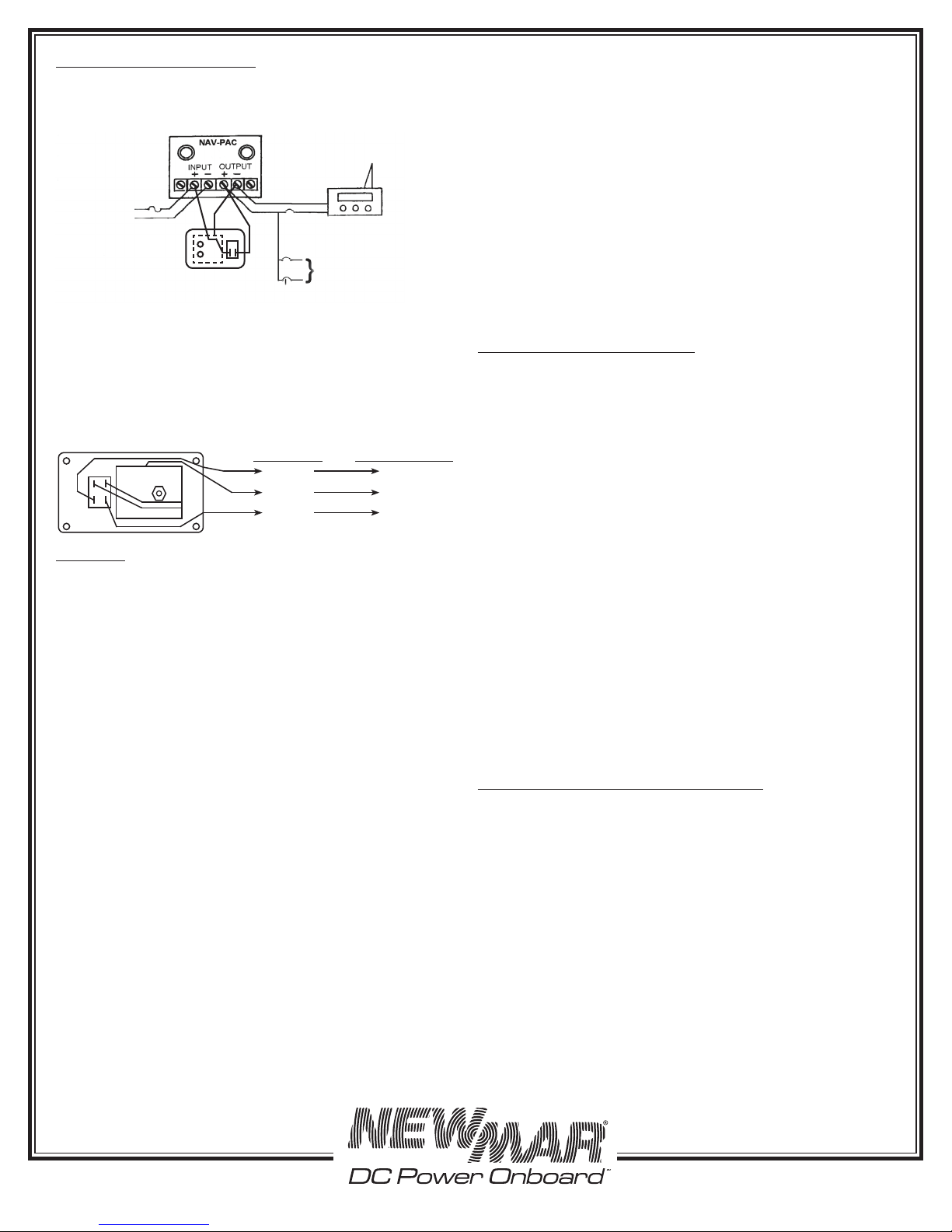
Typical Installation Diagram
3) Remote Panel: Mount in a conspicuous location where the
loss of power indication will be noticed. The NAV-PAC will
function normally without the remote panel or with the remote
panel switch off. Connect the wiring as follows, see diagram.
Operation
When the remote status panel is properly hooked up and DC
power is being applied to the NAV-PAC, both the “INPUT OK”
and “OUTPUT OK” LED’s will steadily illuminate. This indicates
that pure DC power is available at the output terminals and
that the internal 5.0 amp-hour battery is being kept charged.
(The LED lights draw only about .01 amp each.)
In the event of a loss of DC input to the NAV-PAC, the navigation
equipment is being powered by the NAV-PAC’s internal battery
only. The timed battery disconnect circuit will initiate. After
approximately 15 minutes with no DC input, the NAV-PAC’s
internal battery will automatically disconnect from the NAV-
PAC’s output. This is to protect the battery discharge if the
input is switched off. To reset this circuit, input to the NAV-PAC
must be restored. The timer will automatically reset once DC
input voltage recovers.
Bear in mind that the NAV-PAC has another disconnect
circuit which may cause it to shut down sooner. The battery
is also protected by a low-voltage disconnect circuit. Should
the current draw of teh device being powered cause the
battery voltage to drop to 10.2 VDC before 15 minutes have
passed, then this circuit will disconnect the battery from the
output. The amount of time the equipment will continue to
function normally before the NAV-PAC will shut down will
depend, in this case, upon the current draw of the device
being powered. (See Back-Up Power in the Specifications
section.) To reset this circuit, the internal battery must be
recharged. Reduce or shut off the electronic load, and insure
that an adequate charge voltage is restored to the input. (See
Battery Charging/Replacement).
If you are unable to restore DC power immediately, it is probably
a good idea to turn off the equipment being powered by the
NAV-PAC. Most communication or navigation equipment
with built-in memory has a “keep alive” or “soft” shutdown
that is activated by the on/off switch. But if the input voltage
is slowly reduced, as will occur when the NAV-PAC battery
discharges, this “keep alive” feature may not activate, resulting
in loss of memory, waypoints, etc.
Remember: When you wish to shut off your comm/nav
equipment, you must shut it off with the power switch to the
equipment itself. Do not shut off the input to the NAV-PAC.
The NAV-PAC will simply treat this the same as an emergency
loss of DC input, and will continue to supply the comm/nav
equipment with DC power from its internal battery until auto-
shutdown occurs.
Battery Charging/Replacement
Caution: Do not leave the battery discharged for extended
periods of time. It may be permanently damaged and may
not take a recharge.
The battery requires no maintenance and is completely
sealed. Battery life is up to five years. To charge, the battery
requires an input voltage of 13.8 to 14.8 VDC for 3-4 hours or
more per month. To prevent discharging, the battery requires
a nominal input of 13.4 to 14.4 VDC. These voltages are
normally produced by an engine alternator or good quality
battery charger.
The battery storage time @ 23° C is 400 days. The battery
should be replaced no less frequently than every three (3)
years to guarantee proper operation of the NAV-PAC. (Request
P/N 591-0412-0).
To determine the age of the battery in your NAV-PAC, check
the quality control sticker on the end of the unit. The first four
digits of the serial number (designated “S/N”) refer to the year
and month of manufacture. For instance, a unit with a serial
number starting “1535” was manufactured the 35th week of
2015. Be sure to mark the date of replacement on this sticker
for future reference.
Battery Replacement Proceeds as Follows
Caution: Take care to ensure that you do not short the battery
terminals during installation. The resulting high current can
melt wires and cause other damage to the unit.
1) Turn off power to the input wiring and disconnect all input
and output connections to the NAV-PAC. Remove the unit
from the mounting surface.
2) Remove the fuse from the fuseholder labeled “BATTERY”
on the front panel.
3) Remove the four screws on the top of the unit and the four
screws on either side of the unit.
4) Remove the cover.
5) Disconnect the wires from the battery terminals.
6) Remove the four (4) screw/washer sets from the forward
battery braket. Slide out the battery bracket and battery from
beneath the PCB.
Critical 24V Equipmment
(Ground following
manufacturer’s
instructions)
To Other Criti-
cal 24V Loads
DC
INPUT
(Connect to
fused, un-
switched DC
source or one
which is always
powered)
(+)
(-)
Circuit Breakers
(Optional)
RED BLK
Orange
Black
Red
(+) Output
(-) (Output)
(+) Input
From Remote
To NAV-Pac
Terminals Labeled
Rear View: Power Status Panel
Remote panel wiring should be 18 AWG and
may be up to 100’
Note: Remove both fuses before wiring the NAV-PAC. Re-install fuses
only after carefully checking installation and wiring.
ORG

P.O. Box 1306
Newport Beach
California 92663
Phone: 714-751-0488
Fax: 714-957-1621
www.newmarpower.com
7) Carefully observing battery terminal location and polarity,
slide the replacement battery and fbattery bracket in beneath
the PCB.
8) Re-install the four battery bracket screw/washer sets for
the battery bracket and securely tighten all four (4) battery
bracket screws.
9) Re-connect the battery series jumper wire and the -12V
Battery Black and +12V Battery Red to the correct terminals.
10) Re-install cover, fuses, 12 volt output and input connections,
and verify equipment receives 12 volt power.
11) See paragraph 1 of “Test/Troubleshooting” section to verify
back-up power operation.
Dispose of the old battery properly and according to local
codes. Although the batteries are sealed, they are a lead-acid
type and there maybe restrictions on its disposal.
Test / Troubleshooting
To test the battery operation, disconnect the input power at
the source or remove the input fuse, and, using a voltmeter,
note that the DC output power is still present on the output
terminals. Note that after approximately 15 minutes, the output
will disconnect automatically to protect the internal
battery. You should then measure no voltage on the output
terminals. To reset this timed circuit, reconnect the NAV-PAC
input to the ship/vehicle’s battery.
The noise filtering and spike protection circuitry won’t require
testing unless the NAV-PAC blows fuses repeatedly, or has had
a nearby lightning strike, or other very high energy transient.
If the NAV-PAC blow fuses repeatedly (replace with 20 Amp
Fast Acting Fuse: ABC-20 or AGC-20), this usually indicates a
shorted component. Have a qualified technician perform the
repairs or return the unit to NEWMAR for factory inspection.
Always verify that the replaced fuses are of the correct rating.
Use standard or fast-blow fuses. Do not use slow-blow fuses.
Theory of NAV-PAC Operation
Noise Filter/Voltage Transient Protector with Battery Back-Up
The NAV-PAC is wired in series with the DC power to sensiitive
electronics and:
1) Filters out noise interference on incoming power lines
2) Clamps voltage spikes and transients to a safe level
3) Provides battery back-up power during votlage drops due
to starter motors and momentary losses of power.
Specifications
Input: 12 VDC, Nominal Charging: 13.8-14.8VDC
To Prevent
Discharge: 13.4-14.4 VDC, Maximum 15.5 VDC
Output: Filtered, Voltage Spike Protected with
Back-UP Battery 20 amps max
Back-Up Power: 12 VDC Nominal
5.0 AH Capacity
10.9 amps for Fifteen (15) Minutes
16 amps for Eight (8) Minutes
15 amps for Ten (10) Minutes
20 amps for Five (5) Minutes
Battery: Sealed Rechargeable Lead-Acid 5.0 AH,
3 - 5 Years
Typical Life - Replaceable
Filtering: Audio Through 200 MHz
Voltage Spike Protection:
Transient Energy Capability; 100 Joules,
4,000 amps Max.
Operating Temperature:
0-50° C
Size/Weight: 5.49” H x 6.0” W x 7.4” D; 5.2 Lbs.
13.9 H x 15.2 W x 18.8 D (cm); 2.4 Kgs.
Other NewMar Protection Device manuals