vi
Table 3 - Laser Link Conditions ____________________________________________________ 52
Table 4 - TEC Connector Pintouts __________________________________________________ 54
Table 5 - TEC Link Conditions _____________________________________________________ 60
Table 6 - Comparison of Curve Fitting Equations ______________________________________ 64
Table 7 - Thermistor Constants_____________________________________________________ 65
Table 8 - RTD Constants__________________________________________________________ 70
Table 9 - Recommended Test Equipment______________________________________________ 73
Table 10 - Drive Current Load Resistor Selection ______________________________________ 74
Table 11 - Recommended Test Equipment_____________________________________________ 80
Table 12 - Error Codes ___________________________________________________________ 93
Figures
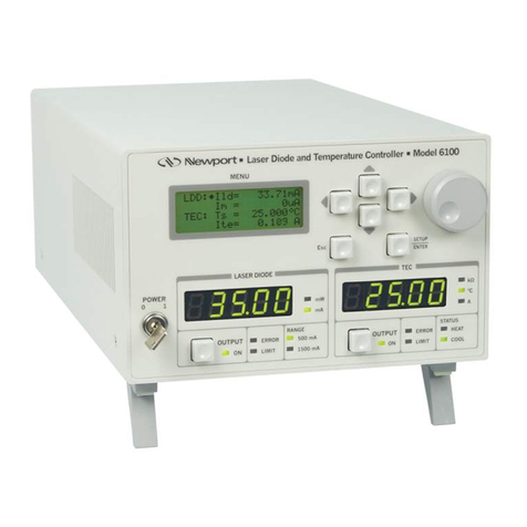
Figure 1 - Model 6000 Front Panel __________________________________________________ 9
Figure 2 - A Sample Screen with Various Data Fields ___________________________________ 13
Figure 3 - Model 6000 Menu Structure_______________________________________________ 14
Figure 4 - Master Display _________________________________________________________ 15
Figure 5 - MOPA Master Display ___________________________________________________ 15
Figure 6 - Main Menu ____________________________________________________________ 16
Figure 7 - Configure Menu ________________________________________________________ 16
Figure 8 – System Configure Screen _________________________________________________ 17
Figure 9 - Save/Recall Screen______________________________________________________ 18
Figure 10 - Link Screen___________________________________________________________ 18
Figure 11 - Communications Screen_________________________________________________ 20
Figure 12 - Rear Panel ___________________________________________________________ 21
Figure 13 - 6000 Block Diagram ___________________________________________________ 23
Figure 14 - Laser Module Block Diagram ____________________________________________ 24
Figure 15 - Constant Current - High Bandwidth Mode __________________________________ 26
Figure 16 - Constant Current - Low Bandwidth Mode ___________________________________ 27
Figure 17 - Constant Power Mode __________________________________________________ 28
Figure 18 - TEC Board Module Diagram_____________________________________________ 29
Figure 19 - Microprocessor Board Block Diagram _____________________________________ 33
Figure 20 - Power Supply Block Diagram ____________________________________________ 35
Figure 21 - Laser Diode Protection Circuit ___________________________________________ 40
Figure 22 - Common Laser Cathode / Photodiode Cathode_______________________________ 45
Figure 23 - Common Laser Cathode / Photodiode Anode ________________________________ 45
Figure 24 - Common Laser Anode / Photodiode Cathode ________________________________ 45
Figure 25 - Common Laser Anode / Photodiode Anode __________________________________ 45
Figure 26 - Laser Main Screen _____________________________________________________ 46
Figure 27 - Laser Setup Screens ____________________________________________________ 48
Figure 28 - MOPA Laser Setup Screens ______________________________________________ 49
Figure 29 - TEC Main Screen ______________________________________________________ 54
Figure 30 - TEC Setup Screens _____________________________________________________ 56
Figure 31 - Thermistor Temperature Range ___________________________________________ 61
Figure 32 - Thermistor Resistance versus Temperature __________________________________ 64
Figure 33 - AD590 Nonlinearity ____________________________________________________ 67
Figure 34 - IPD Calibration Circuit __________________________________________________ 76


