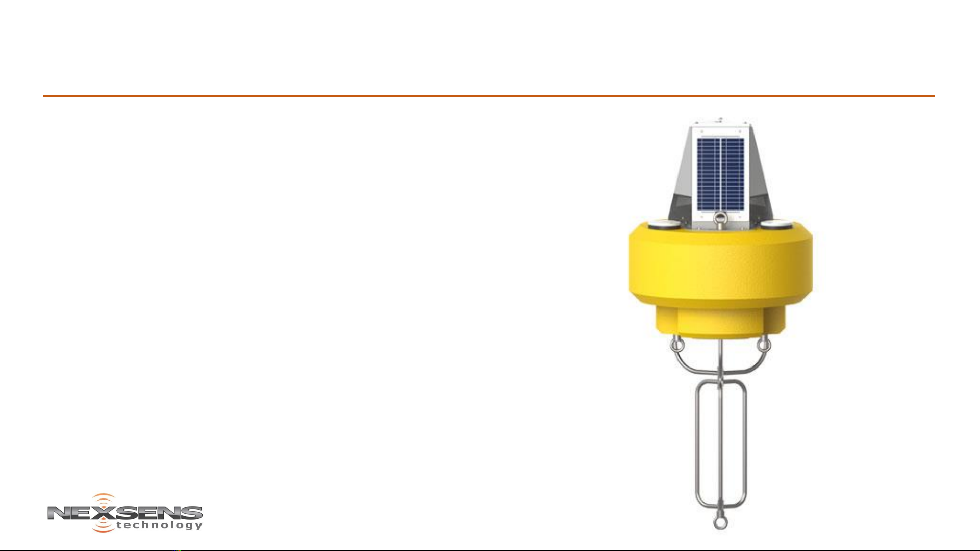
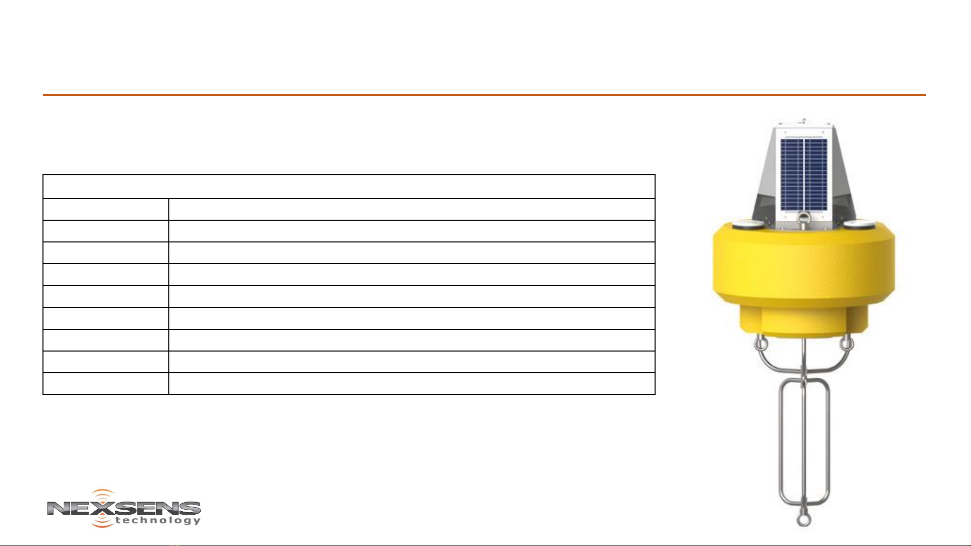
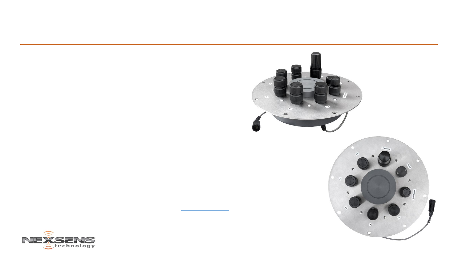
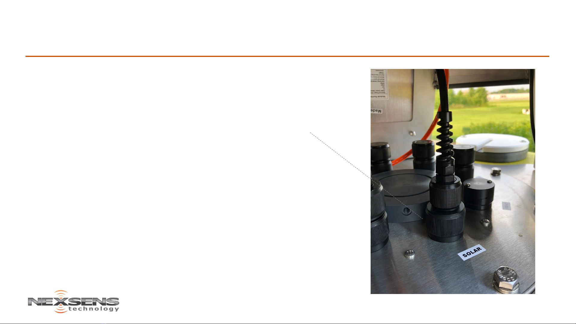
NexSens CB-450 Data Buoy User manual

CB-450 Data Buoy –Quick Start Guide
The NexSens CB-450 Data Buoy is designed for deployment in lakes, rivers,
coastal waters, harbors, estuaries and other freshwater or marine
environments. The floating platform supports both topside and subsurface
environmental monitoring sensors including weather stations, wave sensors,
thermistor strings, multi-parameter sondes, and other monitoring
instruments.
What’s Included:
•(1) Buoy hull with data well
•(3) 10W Solar panels (mounted to tower)
•(1) Data well lid
•(3) Top-side lifting eyes
•(3) Bottom-side mooring eyes
•(1) Instrument cage

CB-450 Data Buoy –Accessories
The CB-450 Data Buoy is a platform and can be accessorized with any of the following
components or users can configure the buoy with alternatives.
Common Accessories
CB-A05-1 Battery harness with integrated solar regulator & (1) 28 A-Hr battery
CB-A05-2 Battery harness with integrated solar regulator & (2) 28 A-Hr batteries
X2-CB Buoy-mounted data logger
X2-CB-C-VZ4G Buoy-mounted data logger with Verizon 4G cellular telemetry
X2-CB-I Buoy-mounted data logger with Iridium satellite telemetry
X2-CB-R-DG Buoy-mounted data logger with 900 MHz radio telemetry
M550-F-Y Solar marine light with flange mount, 1-3 nautical mile range, 15 flashes/minute, yellow
914M Deployment pipe with stop bolt & threaded adapter, 4” PVC
CB-ZA Sacrificial zinc anode for CB-Series data buoys

CB-450 Step-by-Step Assembly
Attach the cage to the buoy frame:
1 Attach the cage to buoy frame using the ¾” bolt, lock washer
and castle nut.
2 Tighten firmly with 1-1/8” wrenches or large crescent wrenches.
Be sure to flatten the lock washer and lineup the hole in the bolt
with the notches in the castle nut.
3 Place the cotter pin through the hole in the bolt, and bend the
long leg of the pin to prevent the nut from coming loose.

CB-450 Step-by-Step Assembly
Understanding the data well with NexSens data loggers
The data well is a waterproof canister located in the center of the buoy hull. Batteries are
secured at the bottom and a data logger is mounted to the underside of the lid. The data well
lid provides convenient connection ports for sensors, an antenna, solar charging, and a vent.

CB-450 Step-by-Step Assembly
Understanding the NexSens data logger ports
Ports include:
•(5) sensor input ports
P0A - 12V switch power, shared RS-232 with port P0B, SDI-12, RS485
P0B - 12V switch power, shared RS-232 with port P0A, SDI-12, RS485
P1A - 12V switch power, shared RS-232 with port P1B, SDI-12, RS485
P1B - 12V switch power, shared RS-232 with port P1A, SDI-12, RS485
P2 - 12V switch power, unique RS-232 port, SDI-12, RS485
•(1) Solar charging port
•(1) Gortex vent for relief of battery outgassing pressure. In heavy wave conditions this
vent can be plumbed with tubing to the top of the tower.
•Antenna port
Note: Sharing RS-232 ports means that only one non-addressable device can be
connected at a time. RS-485 and SDI-12 ports are shared throughout the bus.
Note: To connect analog sensors (i.e. 4-20mA, 0-2.5V) use the mV-RS485 adaptor

CB-450 Step-by-Step Assembly
Understanding sensor ports
For compatibility sensors must have either factory installed UW connectors, be connected
using a UW Plug and Flying Lead cable or be wired using the UW Field Wireable Plug
Recommendation: Invest in factory connectorization of all sensors for a long-term robust
and waterproof connection
Lid receptacle connector pinout
1 Green RS-485 A
2 Blue RS-485 B
3 Brown SDI-12
4 Red 12VDC
5 White 5 VDC
6 Yellow RS232 Rx
7 Black Gnd
8 Orange RS232 Tx
UW to Flying Lead Cable
UW Field Wireable Plug

CB-450 Step-by-Step Assembly
Connecting power
Three solar panels provide charging energy by sunlight exposure while the buoy is free to
move and rotate in any direction.
Connect the 6-pin solar panel plug into the COM/SOLAR port on the data well lid and the
solar panels will provide power to the charge regulator, which will keep the internal
batteries charged.
Note: The device will beep once when powered on

CB-450 Pre-deployment Testing
Perform system tests
Important: Never deploy the buoy without first preforming all system tests.
Check that the battery voltage is near 12VDC by placing the leads of a voltmeter on pins 4 (red) and 7 (black) of a P0A or POB.
Note the voltage and the proceed to checking the solar charging.
Check solar charging by placing the buoy in direct sunlight with at least one panel facing the sun. Allow it to charge for several
hours and then immediately check the voltage again. It should be greater than 12.5 VDC.
Note: If the voltage is low, allow it to charge for an extended period of time.
Connect sensors and establish communications using the WQData Live Datacenter or if you purchased a PC controllable
data logger use iChart Software.
Confirm all sensors are reporting correct values, that the time/date and sample intervals are correct.
Check system diagnostics for any out of range errors.
1
2
3

CB-450 Deployment
SAFETY FIRST
Warning: It highly recommended that buoys are installed by professionals with training in marine safety. Anchors, chains, heavy gear
and boat clutter during deployment is unsafe. Care must be taken during deployment to maintain a clean and safe environment.
Use of proper equipment (work boat, lifting rig, gloves, safety footwear, etc.) is essential to safely deploy any buoy system. Buoy
systems are heavy and personnel can quickly become entangled with mooring lines and anchors. Safety and flotation gear should be
worn at all times when working on or near the water.
NEVER EVER work in unsafe conditions, without safety gear, proper equipment or use unsafe practices.

CB-450 Deployment
Installing sacrificial anodes
Important: To avoid excessive corrosion on buoy frames and
cages always use sacrificial anodes and isolate dissimilar metals in
saltwater applications.
Install the CB-Series Buoy Zinc Anode to both the cage and buoy
frame. The anode will slowly corrode away. Inspect and replace as
needed.

CB-450 Deployment
Understanding ballast weight and stability
Important: To prevent overturning and ensure stability, additional ballast weight may be needed.
As configured at the factory, the center of gravity of the buoy is near the water surface. A single point
mooring line and chain, connected to the eye at the bottom of the cage is typically enough weight to
ensure stability.
Any weight added above the water surface must be appropriately counterbalanced by additional ballast
weight below the surface. Be sure to keep topside devices lightweight and positioned as low as possible on
the tower and bottom side weight centrally located and deep (mounted to the cage eye).
Before deployment, some experimentation may be required to properly balance the buoy. If needed, add
½” chain (~2.3lb/ft) or other weight to the bottom of the cage as shown.

CB-450 Deployment
Single point mooring
Single-point moorings are used in calm waters when monitoring sensors are
attached to the instrument cage or housed in deployment pipes. The sensors
are thus protected and less vulnerable to damage caused by subsurface debris,
high currents, and entanglement from anchor lines.
In a single-point configuration, a stainless steel mooring line connects the buoy
directly to a bottom chain and anchor. At normal pool/stage, the mooring line
should be taut, with most of the bottom chain resting on the seafloor. As the
water level increases and the buoy rises, the bottom chain is lifted from the
floor.
Important: This section contains only general information on the available
mooring options for CB-450 data buoys. To develop an effective mooring strategy,
a variety of application-specific criteria (water level fluctuations, currents and
wave action, debris loads, etc.) must be thoroughly reviewed prior to deployment.
NexSens does not endorse any particular mooring strategy for any specific
application.

CB-450 Deployment
Two point mooring
Two-point moorings are commonly used when monitoring sensors are
deployed in the water column below the buoy. In this setup, the mooring
lines are pulled taut away from the buoy, freeing the water column for a
suspended sensor line.
In most two-point configurations, mooring lines connect the data buoy to
small marine marker floats, often located on the water surface. These marker
floats are shackled to another mooring line that runs to the floor and
connects to a bottom chain and anchor assembly. Additional subsurface
marker floats may also be used in some applications. As in single-point
systems, the bottom chain prevents buoy submersion as the water level
fluctuates.
Important: This section contains only general information on the available
mooring options for CB-450 data buoys. To develop an effective mooring
strategy, a variety of application-specific criteria (water level fluctuations,
currents and wave action, debris loads, etc.) must be thoroughly reviewed prior
to deployment. NexSens does not endorse any particular mooring strategy for
any specific application.
Table of contents
Other NexSens Marine Equipment manuals