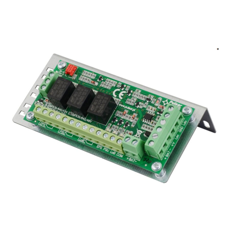
Nexta Tech PLANO-V10/4 User manual

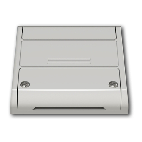
Universal control unit for single colour constant voltage LEDs 12-24Vdc, selectable software for outputs number.
Power supply 12-24Vdc, Max 5A /output (max 10A total).
Integrated 433.92 MHz radio receiver.
note: voice control compatibility
is only available where 4
synchronised outputs are set
PLANO-V10/4

INDEX
1 - PRODUCT FEATURES
1.1 - TECHNICAL DATA page 3
2 - CONNECTION DIAGRAMS
2.1 - SINGLE-COLOR CONNECTION DIAGRAM
2.2 - CONNECTING TWO LINES OF SINGLE-COLOUR STRIP LIGHTS
2.3 - CONNECTING THREE LINES OF SINGLE-COLOUR STRIP LIGHTS
2.4 - CONNECTING FOUR LINES OF SINGLE-COLOUR STRIP LIGHTS
page 4
page 5
page 6
page 7
3 - LED TYPE SETTING
3.1 - TYPES OF SELECTABLE LEDs
3.2 - PROCEDURE FOR LED TYPE SETTING
page 8
page 9
4 - USE OF THE CONTROL UNIT
4.1 - TYPICAL INSTALLATION
4.2 - USE VIA WIRE
4.3 - USE VIA RADIO
page 10
page 11
page 11
5 - CONTROL BY RADIOTRANSMITTERS
5.1 - RADIOTRANSMITTER SETTING
5.2 - DELETION OF RADIOTRANSMITTERS
page 12
page 13
6 - ADVANCED PROGRAMS
6.1 - BUTTON FUNCTION OF THE “WIRELESS BUS” RADIOTRANSMITTER TYPE
6.2 - LOAD STATE WHEN THE CONTROL UNIT IS SWITCHED ON
6.3 - TIMED ON SETTING
6.4 - WIRED INPUT SETTING
6.5 - FACTORY SETTINGS, RESET CONTROL UNIT
page 14
page 16
page 17
page 18
page 19
2

1 - PRODUCT FEATURES
1.1 TECHNICAL DATA
Connectors
cover
Button 1 Hidden key
Button 2
Led
Power supply (Input) 12 - 24 Vdc
LED type (Output) Constant tension
single color LED
Max power load (Output) 5A per output,
max 10 A total (4 outputs)
N° of programmable transmitters 30
RF receiver frequency 433.920MHz
Protection rating IP20
Working temperature -20° +55°
Box dimensions 80 X 80 h16 mm
3
80
80 16

2 - CONNECTION DIAGRAMS
This control unit can manage 1, 2, 3 or 4 lines of single-colour LED strip lights. By default, operation is set to
two single-colour strip lights. If a different strip type is used, follow the paragraph 3 procedure.
RECOMMENDATIONS
• Installation must be carried out only by professional technicians in accordance with the applicable electrical and
safety regulations.
• All connections shall be operated without electrical voltage.
• Use proper cables.
• Don’t cut the antenna
• Provide in the power line twith an appropriate disconnection device
• Dispose of waste materials in full compliance with local law.
• Do not exceed the specied load limits and use correctly protected power supplies.
2.1 SINGLE-COLOR CONNECTION DIAGRAM
The control unit is set by default to manage two lines of single-colour strip lights.
To change the setting, follow the procedure in paragraph 3.
Power supply
12/24Vdc
Single-color
LED
WARNING:
• Connect up to 5A per output and max total 10A
• The outputs are synchronized
Button
USE VIA WIRE
SHORT PRESS:
On-Off for all lights
LONG PRESS:
Up/down dimmer for all lights
4
-+
(1) (2) (9) (10)
-+
(3) (4) - --
(5) (6) +
(7) (8)
OUT 1
+ OUT 1-2
+ OUT 3-4
OUT 2
OUT 3
OUT 4
C
P

2.2 CONNECTING TWO LINES OF SINGLE-COLOUR STRIP LIGHTS
By default, operation is set to two single-colour strip lights.
Power supply
12/24Vdc
LED line
1
LED line
2
WARNING:
• Connect up to 5A per output and max total 10A
• The operation of outputs 1 and 2 (terminals 4 and 5) is synchronised.
• The operation of outputs 3 and 4 (terminals 6 and 7) is synchronised.
Button
USE VIA WIRE
SHORT PRESS: On-Off for all lights
LONG PRESS: Up/down dimmer for all lights
5
-+
(1) (2) (9) (10)
-+
(3) (4) - --
(5) (6) +
(7) (8)
OUT 1
+ OUT 1-2
+ OUT 3-4
OUT 2
OUT 3
OUT 4
C
P

USE VIA WIRE
SHORT PRESS: On-Off for all lights
LONG PRESS: Up/down dimmer for all lights
Power supply
12/24Vdc
3 lines of single-colour
LEDs individuellement
Push button
WARNING:
• Connect up to 5A per output and max total 10A
• The outputs operate separately.
2.3 CONNECTING THREE LINES OF SINGLE-COLOUR STRIP LIGHTS
The control unit is set by default to manage two lines of single-colour strip lights.
To change the setting, follow the procedure in paragraph 3.
6
-+
(1) (2) (9) (10)
-+
(3) (4) --
(5) (6) +
(8)
OUT 1
+ OUT 1-2
+ OUT 3
OUT 2
OUT 3
C
P

USE VIA WIRE
SHORT PRESS: On-Off for all lights
LONG PRESS: Up/down dimmer for all lights
Power supply
12/24Vdc
4 lines of single-colour
LEDs managed separately
Push button
WARNING:
• Connect up to 5A per output and max total 10A
• The outputs operate separately.
2.4 CONNECTING FOUR LINES OF SINGLE-COLOUR STRIP LIGHTS
The control unit is set by default to manage two lines of single-colour strip lights.
To change the setting, follow the procedure in paragraph 3.
7
-+
(1) (2) (9) (10)
-+
(3) (4) --
(5) (6) -
(7) +
(8)
OUT 1
+ OUT 1-2
+ OUT 3-4
OUT 2
OUT 3
OUT 4
C
P

3 - LOAD TYPE SETTING
Default: One line of single-colour LEDs.
This procedure allows you to change the type of the connected LED.
WARNING:
- The procedure of connection with the OneSmart APP (see paragraph 6) must be repeated each time the load type is
changed.
- The wired button always controls all LED lines in synchronised mode.
3.1 SELECTABLE LED TYPES
1. ONE LINE OF SINGLE-COLOUR LEDS
- The control unit is set to manage 4 lines of single-colour LED strip lights in synchronised mode
2. TWO LINES OF SINGLE-COLOUR LEDS
- La centrale viene impostata per gestire 2 linee di strip led: OUT 1 e 2 in parallelo e OUT3 e 4 in parallelo
3. THREE LINES OF SINGLE-COLOUR LEDS
- The control unit is set to manage 3 lines of LED strip lights: OUT 1, 2 and 3 singularly or in groups
4. FOUR LINES OF SINGLE-COLOUR LEDS
- The control unit is set to manage 4 lines of LED strip lights: OUT 1, 2, 3 and 4 singularly or in groups
ATTENTION : en fonction de la conguration du type de charge, un dimensionnement différent de l’alimentateur peut être
nécessaire
8

3.2 - PROCEDURE FOR SETTING THE LED TYPE
PROCEDURE
STEP 1
Press and hold buttons 1 and 2 simultaneously
(approximately 2 seconds) until the LED becomes
green.
STEP 2
Make a short press of button 1 on the receiver and count the
number of LED Flashes.
NUMBER OF
FLASHES
NUMBER OF LINES MANAGED
SEPARATELY
DESCRIPTION
1 1 4 single-colour LED strip lights in synchronised
mode.
2 2 2 lines of single-colour LED
3 3 3 lines of single-colour LED
4 4 4 lines of single-colour LED
STEP 3
Press the button P1 during the during the Flash that
corresponds to the function desired to end the count.
The yellow LED on the board blinks a number of times
corresponding to the set function
WARNING: if no setting is conrmed during step 3, the control unit mantains the load type previously set.
ACTION: Long press of buttons 1 and 2 LED: green
ACTION: Short press button 1 LED: yellow blinking
ACTION: Short press button 1
LED: Count the nuber of Flashes
9

4 - USE OF THE CONTROL UNIT
4.1 TYPICAL INSTALLATION
The system can be controlled by a wired push button, radio commands, smartphone App OneSmart or voice commands.
The installation can operate with only radio controls or application only.
Instead, to use voice commands, at least the App conguration must be completed.
NEXTA CONTROL UNIT
RADIOTRANSMITTER
CONFIGURATION
See paragraph 5
10

4.2 USE VIA WIRE
The wired button always controls all connected LED lines for the On/Off function (press and release) and the Up/Down
dimmer (press and hold).
4.3 USE VIA RADIO
To control the loads via radio you must have compatible transmitters and therefore must carry out the association
procedure, see paragraph 5.
11

STEP 2
Within 60 seconds make a transmission with the transmitter
to be saved.
See transmitter manual, the paragraph entitled “transmitter
programming” for specify information.
The led makes 3 Flashes and turns off.
5 - MANAGEMENT WITH REMOTE CONTROL
This procedure lets you programme/delete compatible multifunctional or generic (Wireless bus) transmitters.
Multifunctional transmitters:
With multifunctional transmitters the transmitter control modes depend on the model used.
Refer to the transmitter manual, to the paragraph entitled “commands sent by the transmitter”, bearing in mind that:
this is a dimmer device.
Generic (wireless bus) transmitters:
With generic transmitters, the function of the button is:
SHORT PRESS: On/Off
LONG PRESS: dimmer Up/Down
The functions of the generic transmitters can be customized using the procedure in paragraph 8.1.
5.1 - RADIO PROGRAMMING
This procedure lets you programme compatible multifunctional or generic transmitters.
Depending on the number of lines of LED strip lights set with the procedure in paragraph 3, the remote control can be
programmed for the active outputs.
ACTION: Make a transmission with the transmitter LED: Flashes 3 times
PASSO 1a
Press key 1.
The LED lights up
red.
PASSO 1b
Press key 1 as many times
as the output number
on which you want to
program the transmitter
PASSO 1d
Press key 1 as many times
as the output number
on which you want to
program the transmitter
PASSO 1c
PPress key 1 as many times
as the output number
on which you want to
program the transmitter
1 LINE OF LEDS
(see paragraph 3)
2 LINES OF LEDS
(see paragraph 3)
4 LINES OF LEDS
(see paragraph 3)
3 LINES OF LEDS
(see paragraph 3)
no. of
presses
LED
colour
Output
paired
with TX
1 red OUT1-2
2 green OUT3-4
3 off /
no. of
presses
LED
colour
Output
paired
with TX
1 red OUT1
2 green OUT2
3 blu OUT3
4 yellow OUT4
5 off /
no. of
presses
LED
colour
Output
paired
with TX
1 red OUT1
2 green OUT2
3 blu OUT3
4 off /
X1 OUT1 (RED)
X2 OUT2 (GREEN)
X3 LED OFF
X1 OUT1 (RED)
X2 LED OFF
X1 OUT1 (RED)
X2 OUT2 (GREEN)
X3 OUT3 (BLU)
X4 LED OFF
X1 OUT1 (RED)
X2 OUT2 (GREEN)
X3 OUT3 (BLU)
X4 OUT4 (YELLOW)
X5 LED OFF
12

STEP 1
Hold the receiver button 1 down (about 5 seconds.) until the
LED begins to Flash.
DELETION OF SINGLE
TRANSMITTER
DELETION OF ALL
TRANSMITTER SAVED
5.2 - DELETION OF REMOTE CONTROL
These procedures let you delete from the memory transmitters that have already been programmed.
STEP 2a
Within 10 seconds make a transmission with the
transmitter that you want to delete.
The LED ashes quickly and turns off.
STEP 2B
Within 10 seconds press the button 1 on
the receiver for a short time to conrm the
delection of all transmitters.
The LED starts ashing quickly and turns off.
ACTION: Hold tbutton 1 down LED: Flashes red
ACTION: Make a transmission with the transmitter
LED: Flashing quickly and turns off
ACTION: Short press of button 1
LED: Flashing quickly and turns off
13

6 - ADVANCED PROGRAMS
6.1 FUNCTION CUSTOMIZATION OF THE “WIRELESS BUS” GENERIC TRANSMITTER BUTTONS
The following procedure allows you to set a custom function to the “wireless bus” family transmitter button.
Details on selectable functions.
Function 5 - Memo
Each time the button is pressed, the load will Flash to indicate that the current state of the light is stored.
If the button is pressed from state “light off”, the storage is switched off and the light will be turned back on to the last set
value, as it is by default.
14

PROCEDURE
STEP 1
Press key 1 as many times as the output number on which you want to program
the transmitter
no. of presses LED colour Output paired with TX
1 red OUT1
2 green OUT2
3 blu OUT3
4 yellow OUT4
5 off /
STEP 4
Make a transmission with the transmitter to be saved
(see transmitter manual, paragraph entitled “transmitter
programming”).
The LED on the receiver Flashes 3.times and turns off.
STEP 2
Press the button 2 on the receiver for a short time and count the number of Flashes emitted by the LED:
NUMBER OF
FLASHES
FUNCTION
1 Off
2 On
3 Short press: On
Long press: Dimmer Up
4 Short press: Off
Long press: Dimmer Down
5 Memo
STEP 3
Press the button for a short time during the Flash that
corresponds to the function desired to end the count.
The led stop Flashes
ACTION: Short press of button 1 LED: Turns on red
ACTION: Short pressure of button 2 during the Flash LED: Stop Flashes
ACTION:
Short press of button 2
LED:
Count the number of Flashes
ACTION: Make a transmission with the transmitter LED: Flashes 3 times
15

6.2 - LOAD STATE WHEN THE CONTROL UNIT IS SWITCHED ON
Default: Last value before the black out
This process is used to set the state of Leds when the control unit is switched on (for example when the power supply is
provided by a general switch or timer).
PROCEDURE:
STEP 2
With a paper clip make a long press of the “hidden” button.
The LED is cyclically yellow and cyane.
Release the key when the led is yellow.
STEP 3
Make a short press on button 2 of the receiver.
The led Flashes yellow and turns off.
STEP 1
set the light on the desired state.
NOTE: light state cannot be set as off.
* function deactivation
To set up the default value, set the light OFF at step 1 of the procedure
ACTION: Long press of the “hidden” button LED: Turns on yellow/cyane
ACTION: Short press of button 2 LED: Flashes
16

6.3 - SETTING THE TIMED ON
Default: 24 hours
This procedure is used to set the time for which the Leds stays on before an automatic switch off.
All commands reset the time count to zero, excluding the following commands that will immediately turn off the light: short
press by wired push button, command OFF by radiotransmitter, comand by App or voice.
PROCEDURE
STEP 1
With a paper clip makes a long press of the “hidden” button.
The LED is cyclically yellow and cyane.
Release the key when the led is yellow.
STEP 2
Press the button 1 on the receiver for a short time and count the number of Flashes emitted by the LED:
FLASHES
NUMBER
FUNCTION
1 No timed on
2 30 seconds
3 1 minute
4 2 minutes
5 5 minutes
6 15 minutes
7 30 minutes
8 1 hour
9 2 hours
10 3 hours
11 8 hours
12 12 hours
13 18 hours
STEP 3
Press the button for a short time during the Flash that
corresponds to the function desired to end the count.
The led turns off
ACTION: Long press of the “hidden” button LED: Turns on yellow/cyane
ACTION: Short press of button 1
LED: Count the number of Flashes
ACTION: Short press of button 1 during the Flashes LED: Turns off
17

6.4 - SETTING TYPE OF INPUTS VIA WIRE
Default: Button function
This procedure lets you choose the type of wired devices to command load (connected on terminals 9 and 10).
The devices can be set as buttons or switches.
PROCEDURE
STEP 1
With a paper clip makes a long press of the “hidden” button.
The LED is cyclically yellow and cyane.
Release the key when the led is cyane.
ACTION: Long press of hidden button LED: Turns on yellow/cyane
STEP 2
Press the button on the receiver for a short time and count
the number of Flashes emitted by the LED:
3 Flashes = control with buttons
6 Flashes = control with switches
ACTION: Short press of button 2 LED: Flashes
STEP 3
To change the setting, repeat the procedure from point 1;
the control unit will alternate between 3 and 6 Flashes
18

STEP 1
Hold the receiver button 1 down (about 5 seconds.) until the
LED begins to Flash.
6.5 - RESET OF THE CONTROL UNIT
This procedure let you take the control unit back to factory settings.
PROCEDURE
STEP 2
Within 10 seconds, make a short press of “hidden” button.
The LED 1 Flashes quickly and turns off.
ACTION: Long press of button 1 LED: Flashes red
ACTION: Make a short press of hidden button LED: the led Flash quicly and turns off
19

20
Table of contents
Other Nexta Tech Control Unit manuals
Nexta Tech
Nexta Tech PLANO-V5/RGBW User manual
Nexta Tech
Nexta Tech MCX-M/ONE User manual
Nexta Tech
Nexta Tech MCX-M500 User manual
Nexta Tech
Nexta Tech TOP-ML/One User manual
Nexta Tech
Nexta Tech PRG-M24 User manual
Nexta Tech
Nexta Tech TOP-M400/One User manual
Nexta Tech
Nexta Tech LOGIC-400-ONE User manual
Nexta Tech
Nexta Tech PLANO-ONE/4 User manual
