manuals.online logo
Brands
  1. Home
  2. •
  3. Brands
  4. •
  5. Siemens
  6. •
  7. Control Unit
  8. •
  9. Siemens LOK16 Series User manual

Siemens LOK16 Series User manual

Other manuals for LOK16 Series

2

This manual suits for next models

11

Other Siemens Control Unit manuals

Siemens SINUMERIK 802D User manual

Siemens

Siemens SINUMERIK 802D User manual

Siemens 3AH User manual

Siemens

Siemens 3AH User manual

Siemens simovert masterdrives User manual

Siemens

Siemens simovert masterdrives User manual

Siemens SIMATIC ET 200SP User manual

Siemens

Siemens SIMATIC ET 200SP User manual

Siemens Simatic S7-1500 User manual

Siemens

Siemens Simatic S7-1500 User manual

Siemens SINUMERIK 802D sl Owner's manual

Siemens

Siemens SINUMERIK 802D sl Owner's manual

Siemens SINUMERIK User manual

Siemens

Siemens SINUMERIK User manual

Siemens SIRIUS ACT 3SU1803-3NB00-1AE1 User manual

Siemens

Siemens SIRIUS ACT 3SU1803-3NB00-1AE1 User manual

Siemens SINUMERIK 840D Setup guide

Siemens

Siemens SINUMERIK 840D Setup guide

Siemens 8F-DI Ex NAMUR User manual

Siemens

Siemens 8F-DI Ex NAMUR User manual

Siemens SINUMERIK 840D sl User manual

Siemens

Siemens SINUMERIK 840D sl User manual

Siemens Cerberus Pyrotronics LP-30 User manual

Siemens

Siemens Cerberus Pyrotronics LP-30 User manual

Siemens SIMATIC S7 Technical Document

Siemens

Siemens SIMATIC S7 Technical Document

Siemens LGB21.130A17 User manual

Siemens

Siemens LGB21.130A17 User manual
Siemens SIRIUS 3RW5 series User manual

Siemens

Siemens SIRIUS 3RW5 series User manual

Siemens 3KC9826-0 User manual

Siemens

Siemens 3KC9826-0 User manual

Siemens SIRIUS 3SB3 User manual

Siemens

Siemens SIRIUS 3SB3 User manual

Siemens SINAMICS S120 Parts list manual

Siemens

Siemens SINAMICS S120 Parts list manual

Siemens SIMATIC FM 353 User manual

Siemens

Siemens SIMATIC FM 353 User manual

Siemens SINAMICS DCM 6RN User manual

Siemens

Siemens SINAMICS DCM 6RN User manual

Siemens SINUMERIK 840D User manual

Siemens

Siemens SINUMERIK 840D User manual
Siemens SIPROTEC 4 7XT71 Series User manual

Siemens

Siemens SIPROTEC 4 7XT71 Series User manual

Siemens FN2013-U1 User manual

Siemens

Siemens FN2013-U1 User manual

Siemens Modem Block User manual

Siemens

Siemens Modem Block User manual

Popular Control Unit manuals by other brands

Seitz 14A80 user manual

Seitz

Seitz 14A80 user manual

Wilo RS485 Installation and operating instructions

Wilo

Wilo RS485 Installation and operating instructions

Becker CentralControl CC41 Commissioning Instruction

Becker

Becker CentralControl CC41 Commissioning Instruction

SICK CDB650 operating instructions

SICK

SICK CDB650 operating instructions

Panduit NetKey NKP5E88M Series installation instructions

Panduit

Panduit NetKey NKP5E88M Series installation instructions

MX Options Concentric Petite Fitting instructions

MX

MX Options Concentric Petite Fitting instructions

Clean Water Systems Fleck 2510 Installation & start?up guide

Clean Water Systems

Clean Water Systems Fleck 2510 Installation & start?up guide

Fairchild FSB44104A user guide

Fairchild

Fairchild FSB44104A user guide

LEGRAND Wattstopper LMIN-104 installation instructions

LEGRAND

LEGRAND Wattstopper LMIN-104 installation instructions

PMK ATT10BNCS instruction manual

PMK

PMK ATT10BNCS instruction manual

Tektronix TDS3FFT user manual

Tektronix

Tektronix TDS3FFT user manual

Woodward easYgen Technical manual

Woodward

Woodward easYgen Technical manual

Balluff BNI EIP-502-105-R015 user guide

Balluff

Balluff BNI EIP-502-105-R015 user guide

NXP Semiconductors TWR-LS1021A Getting started

NXP Semiconductors

NXP Semiconductors TWR-LS1021A Getting started

Advantech PCM-3117 Startup manual

Advantech

Advantech PCM-3117 Startup manual

Danfoss MCO 101 manual

Danfoss

Danfoss MCO 101 manual

Moons' Lin Engineering R701P user manual

Moons'

Moons' Lin Engineering R701P user manual

Aventics RV1 operating instructions

Aventics

Aventics RV1 operating instructions

manuals.online logo
manuals.online logoBrands
  • About & Mission
  • Contact us
  • Privacy Policy
  • Terms and Conditions

Copyright 2025 Manuals.Online. All Rights Reserved.

CC1N7785en
20.11.2017
Building Technologies Division
7785
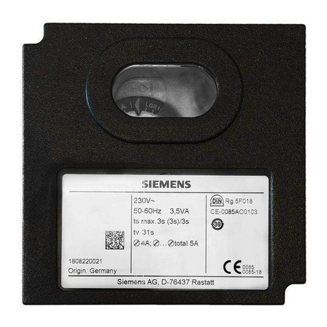
Burner Controls LOK16...
LGK16...
Burner controls
For gas, oil or dual-fuel forced draft burners of medium to high capacity
For multistage or modulating burners in continuous operation
With air pressure supervision for checked air damper control.
Flame supervision
- LOK16: With silicon detector RAR
- LGK16: With flame detector QRA53/QRA55/ionization probe
Burner control for oil burners or gas burners in accordance with EN 298:2012
Suitable for use with air heaters (WLE)
With self-checking flame signal amplifier
The LOK16.../LGK16... and this Data Sheet are intended for use by OEMs which
integrate the burner controls in their products.
2/28
Building Technologies Division CC1N7785en
20.11.2017
Use
Burner controls type LOK16.../LGK16... feature a self-checking flame supervision
circuit.
The flame supervision circuit initiates the safety actions in the case of... :
• ... premature or missing flame signal
• ... any kind of fault on the flame detector, the detector cables or the flame signal
amplifier that could simulate a flame signal during burner operation
The burner controls are therefore suited for use in all types of oil- or gas-fired
combustion plant where self-checking flame supervision systems are either mandatory
or recommended.
For example:
-Burners that operate continuously
-Burners in intermittent operation that, in the case of great heat demand, may
operate continuously for more than 14 hours, e.g. in plant using boiler sequencing
-Burners that need to comply with the German TRD 411 and TRD 412 regulations
for steam boilers
-Burners in plant where, for specific safety requirements, supervision of the burner
by a self-checking flame supervision system seems advisable
-The control sequence and connection circuitry of the LOK16…/LGK16… burner
controls are identical to those of the LAL2... and LFL1... respectively (with the
exception of the LFL1.148), so that existing combustion plant can also be equipped
with self-checking burner controls,
provided very good flame detector current values are measured in the plant
supervised so far by the LFL1..., and
provided the following types of flame detectors are either installed or can
subsequently be fitted:
-Photocell detector RAR9
-Flame detector QRA53.../QRA55...
-Ionization probe
-Flame detector QRA53.../QRA55... together with ionization probe, e.g. in the case
of burners using a pilot burner (also see Data Sheet N7712)
Flame supervision
when using LOK16...
Flame supervision
when using LGK16...
3/28
Building Technologies Division CC1N7785en
20.11.2017
Warning notes
To avoid injury to persons, damage to property or the environment, the following
warning notes must be observed!
Do not open, interfere with or modify the unit!
All activities (mounting, installation and service work, etc.) must be performed by
qualified staff
Before making any wiring changes in the connection area, completely isolate the
plant from mains supply (all-polar disconnection). Ensure that the plant cannot be
inadvertently switched on again and that it is indeed dead. If not observed, there is
a risk of electric shock hazard
Ensure protection against electric shock hazard by providing adequate protection
for the burner control’s connection terminals
Each time work has been carried out (mounting, installation, service work, etc.),
check to ensure that wiring is in an orderly state and make the safety checks as
described in Commissioning notes
Press the lockout reset button only manually (applying a force of no more than
10 N) without using any tools or pointed objects
Do not press the lockout reset button on the unit or the remote reset button
(input 21) for more than 10 seconds, since this would damage the lockout
relay inside the unit
Fall or shock can adversely affect the safety functions. Such units must not be put
into operation, even if they do not exhibit any damage
In the case of flame supervision with flame detectors QRA53 / QRA55, it should be
noted that sources of radiation such as halogen lamps, welding equipment, special
lamps, ignition sparks, as well as X-rays and gamma radiation, can produce
erroneous flame signals
Mounting notes
Ensure that the relevant national safety regulations are complied with.
Connect the earthing lug inside the terminal base to burner ground using a screw
with a lockwasher
An ignited UV tube is a source of UV radiation!
If the flame is monitored by several flame detectors, all detectors must be placed in
a way that ensures there is no direct visual contact between them.
If this is not observed, there is a risk of loss of safety functions
When equipping existing plants with LOK16 or LGK16, the existing plug-in base for LAL
or LFL burner controls must be replaced with the matching plug-in base AGM17 for
LOK16 / LGK16.
By removing link (B) on the underside of the unit, the LOK16... can be switched to start
repetition in the event of loss of flame during operation.
In that case, the wire link must be cut off completely.
However, it must be checked whether this is in compliance with national standards and
regulations.

Note!
In applications involving air heaters (WLE), or in the case of oil burners with a
maximum throughput of > 30 kW/h, removing wire link Bis not permitted.
Upgrading existing plant
Start repetition in the
event of loss of flame
4/28
Building Technologies Division CC1N7785en
20.11.2017
Installation notes
Always run the high-voltage ignition cables separately while observing the greatest
possible distance to the unit and to other cables
Neutral conductors must not be interchanged
Install switches, fuses, earthing, etc., in compliance with local regulations
Make certain that the maximum permissible current rating of the connection
terminals will not be exceeded
The insulation of internal wiring that is exposed to the mains voltage must
withstand the electrical stress occurring during correct use
Application notes
Note!
For use in applications in dual-fuel burners or oil burners, the oil supply must be
equipped with two shutoff valves connected in series.
Observe the following:
EN 298:2012, Section 7.101.3.3 Prepurge time for oil burner control systems and the
corresponding application standards.
Electrical connection of flame detectors
It is important to achieve practically disturbance- and loss-free signal transmission:
Never run the detector cable together with other cables
– Line capacitance reduces the magnitude of the flame signal
– Use a separate cable
Observe the permissible detector cable lengths (see Technical data)
It is not permitted to connect 2 flame detectors QRA53.../QRA55... in parallel
When using the QRA53.../QRA55..., earthing of terminal 22 is mandatory
The ionization probe is not protected against electric shock hazard
Locate the ignition electrode and ionization probe such that the ignition spark
cannot arc over to the ionization probe (risk of electrical overloads) and that it
cannot adversely affect the supervision of ionization
Supervision with ionization probe and QRA53/QRA55 flame detector is possible
but, for safety reasons, both must not be active at the same time, with the
exception of the second safety time (t9). At the end of the second safety time, one
of the detected flames must extinguish, e.g. by shutting down the pilot gas valve
connected to terminal 17
Commissioning notes
When commissioning the plant or when doing maintenance work, make the following
safety checks:
Safety check to be carried out Anticipated response
a) Burner startup with flame detector
darkened
Lockout at the end of safety time
b) Burner startup with simulated flame Lockout after no more than 40 seconds
c) Burner operation with simulated loss
of flame; for that purpose, darken the
flame detector in operation and leave
it in that state
LOK16... with wire link cut: Start
repetition followed by lockout at the end
of safety time
LGK16... and LOK16... with wire link
closed: Immediate lockout
d) Burner startup with response of air
pressure switch
Prevention of startup/lockout during
prepurge time
e) Burner operation with simulated air
pressure failure
Immediate lockout
5/28
Building Technologies Division CC1N7785en
20.11.2017
Commissioning notes
For the connection of valves and other components, the diagram of by the burner
manufacturer is provide.
Standards and certificates
Applied directives:
Low-voltage directive 2014/35/EC
Directive for pressure devices 2014/68/EC
Electromagnetic compatibility EMC (immunity) *) 2014/30/EC
Only LGK16: Directive for gas-fired appliances 2009/142/EC
*) The compliance with EMC emission requirements must be checked after the burner control is
installed in equipment
Compliance with the regulations of the applied directives is verified by the adherence to
the following standards / regulations:
Automatic burner control systems for burners and
appliances burning gaseous or liquid fuels
DIN EN 298
Only LGK16
Safety and control devices for gas burners and gas
burning appliances
DIN EN 13611:
2007-A2:2011
Automatic electrical controls for household and similar use
Part 2-5:
Particular requirements for automatic electrical burner
control systems
DIN EN 60730-2-5
The relevant valid edition of the standards can be found in the declaration of
conformity!
Note on DIN EN 60335-2-102
Household and similar electrical appliances - Safety - Part 2-102:
Particular requirements for gas, oil and solid-fuel burning appliances having electrical
connections.
The electrical connections of the LMV5 and the PLL5 comply with the requirements of
EN 60335-2-102.
EAC Conformity mark (Eurasian Conformity mark)
ISO 9001:2015
ISO 14001:2015
OHSAS 18001:2007
China RoHS
Hazardous substances table:
http://www.siemens.com/download?A6V10883536
6/28
Building Technologies Division CC1N7785en
20.11.2017
Certified with plug-in base and flame detector:
Type reference
LOK16.140... --- --- ---
LOK16.250... --- --- ---
LOK16.650... --- --- ---
LGK16.122... --- --- 
LGK16.133A17 --- --- --- --- 
LGK16.133A27 --- --- 
LGK16.322... --- --- 
LGK16.333... --- --- 
LGK16.335... --- --- 
LGK16.622... --- --- 
LGK16.635... --- --- 
Service notes
The KF8832 flame detector current measuring device must not be used in continuous
operation.
Life cycle
Burner controls has a designed lifetime* of 250,000 burner startup cycles which, under
normal operating conditions in heating mode, correspond to approx. 10 years of usage
(starting from the production date given on the type field).
This lifetime is based on the endurance tests specified in standard EN 298.
A summary of the conditions has been published by the European Control
Manufacturers Association (Afecor - www.afecor.org).
The designed lifetime is based on use of the burner controls according to the
manufacturer’s Data Sheet. After reaching the designed lifetime in terms of the number
of burner startup cycles, or the respective time of usage, the burner control is to be
replaced by authorized personnel.
* The designed lifetime is not the warranty time specified in the Terms of Delivery
Disposal notes
The unit contains electrical and electronic components and must not be disposed of
together with household waste.
Local and currently valid legislation must be observed.
Mechanical design
Plug-in design
Exchangeable unit fuse (including spare fuse)
Made of impact-proof and heat-resistant black plastic
Lockout reset button with viewing window; located behind it are:
- The lockout warning lamp
- The lockout indicator
- coupled to the spindle of the sequence switch
- visible in the transparent lockout reset button
- uses easy-to-remember symbols to indicate the type of fault and the point in
time lockout occurred
LGK16.../LOK16...
Housing
7/28
Building Technologies Division CC1N7785en
20.11.2017
Type summary
The type references given below apply to the LOK16 without plug-in base and without
flame detector. For ordering information for plug-in bases and other accessories, see
Accessories.
Switching times are given in the order of the startup sequence, valid for 50 Hz mains
frequency. At 60 Hz, the times are about approx. 17% shorter.
The type references apply to burner controls operating on AC 230 V, 50...60 Hz.
* For burner controls operating on AC 100...110 V, 50...60 Hz, the last 2 digits of the type reference read «17» in place of «27».
For flame supervision with a photocell detector RAR9... for oil burners
Preferred use:
Flash-steam
generators
Universal
application
Medium- or
heavy-oil burners
Type LOK16.140A27* LOK16.250A27* LOK16.650A27
Article
no. BPZ:LOK16.140A27 BPZ:LOK16.250A27 BPZ:LOK16.650A27 Legend of times
t1 10 s 22 s 66 s Prepurge time with air damper fully open
TSA 4 s 5 s 5 s Safety time or first safety time
TSA´ --- --- --- Safety time with burners using a pilot burner
t3 2 s 2.5 s 2.5 s Preignition time
t3´ From startup command (with air pressure supervision:
from receipt of air pressure signal)
Long preignition time
t3n 10 s 15 s 15 s Postignition time (ignition transformer connected to
terminal 15)
t4 8 s 7.5 s 7.5 s Interval between start of safety time and release of
valve at terminal 19
t4´ --- --- --- Interval between start of safety time and release of
valve at terminal 19
t5 4 s 7.5 s 7.5 s Interval between end of interval (t4/t4´) and release of
load controller or valve at terminal 20
t6 10 s 15 s 15 s Postpurge time (identical to permissible afterburn time
(t13))
t7 2 s 2.5 s 2.5 s Switch-on delay of fan motor (M2)
t8 30 s 47 s 91 s Duration of startup without «t11» and «t12»
t9 --- --- --- Second safety time with burners using a pilot burner
t10 6 s 10 s 10 s Interval from startup to the beginning of the air
pressure check
t11 Optional Air damper running time to the fully open position
t12 Optional Air damper running time to the low-fire position
t13 10 s 15 s 15 s Permissible afterburn time
t16 4 s 5 s 5 s Interval from startup to the open command for the air
damper
t20 32 s 34.5 s 12.5 s Interval to self-shutdown of the sequence switch
LOK16...
8/28
Building Technologies Division CC1N7785en
20.11.2017
Type summary (cont’d)
The type references given below apply to the LGK16 without plug-in base and without
flame detector. For ordering information for plug-in bases and other accessories, see
Accessories.
For flame supervision with flame detector QRA53.../QRA55... or ionization probe
Preferred use:
Flash-steam
generators
Flash-steam
generators
Also suited for
direct-fired air
heaters)
Type LGK16.122A27* LGK16.133A27 LGK16.322A27* LGK16.333A27* LGK16.335A27* LGK16.622A27* LGK16.635A27*
Article
no. BPZ:LGK16.122A27 BPZ:LGK16.133A27 BPZ:LGK16.322A27 BPZ:LGK16.333A27 BPZ:LGK16.335A27 BPZ:LGK16.622A27 BPZ:LGK16.635A27
t1 10 s 9 s 35.5 s 31.5 s 37 s 65 s 66 s
TSA 2 s 3 s 2 s 3 s 2.5 s 2 s 2.5 s
TSA´ 2 s 3 s 2 s 3 s 5 s 2 s 5 s
t3 4 s 3 s 4 s 6 s 5 s 4 s 5 s
t3´ 4 s --- 4 s 6 s 2.5 s 4 s 2.5 s
t3n --- --- --- --- --- --- ---
t4 6 s 6 s 10 s 11.5 s 12.5 s 10 s 12.5 s
t4´ 6 s --- 10 s 11.5 s 15 s 10 s 15 s
t5 4 s 3 s 10 s 11.5 s 12.5 s 10 s 12.5 s
t6 10 s 14.5 s 12 s 17 s 15 s 12 s 15 s
t7 2 s 3 s 2 s 3 s 2.5 s 2 s 2.5 s
t8 30 s 29 s 65 s 69 s 74 s 95 s 103 s
t9 2 s 3 s 2 s 3 s 5 s 2 s 5 s
t10 6 s 6 s 8 s 11.5 s 10 s 8 s 10 s
t11 Optional
t12 Optional
t13 10 s 14.5 s 12 s 17 s 15 s 12 s 15 s
t16 4 s 3 s 4 s 6 s 5 s 4 s 5 s
t20 32 s 60 s --- 26 s 22 s --- ---
LGK16...
9/28
Building Technologies Division CC1N7785en
20.11.2017
Accessories (to be ordered separately)
Oil burner controls, without plug-in base
For AC 230 V* Control sequence and
connection diagram like
Preferred use
LOK16.140A27* LAL2.14 Flash-steam generators
LOK16.250A27* LAL2.25 Universal application
LOK16.650A27 LAL2.65 Heavy-oil burners
* For burner controls operating on AC 100...110 V, 50...60 Hz, the last 2 digits of the
type reference read «17» in place of «27»
Connection accessories
for medium-capacity
burner controls
Plug-in base AGM16
Article no.: BPZ:AGM16
- with Pg11 thread for cable entry glands
Plug-in base AGM16.1
Article no.: BPZ:AGM16.1
- with M16 thread for cable entry glands
see Data Sheet N7230
Flame detectors Photocell detectors RAR9...
see Data Sheet N7713
10/28
Building Technologies Division CC1N7785en
20.11.2017
Accessories (to be ordered separately) (cont‘d)
Gas burner controls, without plug-in base
For AC 230 V* Control sequence and
connection diagram like
Preferred use
LGK16.122A27* LFL1.122 Flash-steam generators
LGK16.133A27 LFL1.133 Flash-steam generators
LGK16.322A27* LFL1.322 Also suited for direct-fired
air heaters
LGK16.333A27* LFL1.333
LGK16.335A27* LFL1.335
LGK16.622A27* LFL1.622
LGK16.635A27* LFL1.635
* For burner controls operating on AC 100...110 V, 50...60 Hz, the last 2 digits of the
type reference read «17» in place of «27»
Connection accessories
for medium-capacity
burner controls
Plug-in base AGM17
Article no.: BPZ:AGM17
- with Pg11 thread for cable entry glands
Plug-in base AGM17.1
Article no.: BPZ:AGM17.1
- with M16 thread for cable entry glands
see Data Sheet N7230
Flame detectors Flame detectors QRA53.../QRA55...
see Data Sheet N7712
Ionization probe
to be supplied by thirds