NGX Technologies LPC185X-Xplorer++ User manual

USER MANUAL: LPC185x –Xplorer++
Page | 1
LPC185x-Xplorer++
About NGX Technologies
NGX Technologies is a premier supplier of development tools for the ARM7, ARM Cortex M0, M3 and
M4 series of microcontrollers. NGX provides innovative and cost effective design solutions for embedded
systems. We specialize in ARM MCU portfolio, which includes ARM7, Cortex-M0, M3 & M4
microcontrollers. Our experience with developing evaluation platforms for NXP controller enables us to
provide solutions with shortened development time thereby ensuring reduced time to market and lower
development costs for our customers. Our cost effective and feature rich development tool offering, serves
as a testimony for our expertise, cost effectiveness and quality.
Contact Information:
NGX Technologies Pvt. Ltd.
#12, 20th Cross, Malagala, Nagarabhavi 2nd Stage
Bengaluru - 560091
Phone- +91-80-23185507 / 23188306
email:sales@ngxtechnologies.com

USER MANUAL: LPC185x –Xplorer++
Page | 2
CE certification:
NGX Technologies LPC185X-Xplorer++ board has been tested for radiated emission as per EN55022
class a standard. The device is under the limits of the standard EN55022 class A and hence CE marked.
No other test have been conducted other than the radiated emission (EN55022 class A standard). The
device was tested with the ports like USB, Serial, and Power excluding the GPIO ports. Any external
connection made to the GPIO ports may alter the EMC behavior. Usage of this device under domestic
environment may cause unwanted interference with other electronic equipment’s. User is expected to take
adequate measures. The device is not intended to be used in and end product or any subsystem unless the
user re-evaluates applicable directive/conformance.

USER MANUAL: LPC185x –Xplorer++
Page | 3
Table of Contents
1.0 INTRODUCTION.................................................................................................................................4
2.0 LPC185X-Xplorer++ Development Tool Setup...................................................................................5
2.1 ULINK2/ME and KEIL ....................................................................................................................5
2.2 Installation & Configuration of KEIL software................................................................................5
2.3 Configuration of ULINK2/ME Debugger.........................................................................................9
2.4 Configuring External Quad Flash ...................................................................................................10
2.5 Setup for ULINK2/ME and LPC185X-Xplorer++ Board ..............................................................13
3.0 LPC185X-Xplorer++ firmware Development....................................................................................19
3.1 Creating the sample (Blinky) project in KEIL................................................................................19
3.2 Executing the sample project in KEIL............................................................................................38
4.0 Creating bin file...................................................................................................................................40
5.0 LPC185x-Xplorer++ Programming....................................................................................................41
5.1 Programming options......................................................................................................................41
5.1.1 Programming LPC185x-Xplorer++ using Coflash and ColinkEx...............................................42
6.0 Restoring LPC185X-Xplorer++ to Factory Defaults..........................................................................45
6.1 ULINK2/ME and KEIL ..................................................................................................................45
7.0 Schematic & Board Layout.................................................................................................................46
7.1 Schematic........................................................................................................................................46
7.2 Board layout....................................................................................................................................46
8.0 CHANGE HISTORY..........................................................................................................................47
8.1 Change History................................................................................................................................47

USER MANUAL: LPC185x –Xplorer++
Page | 4
1.0 INTRODUCTION
This document is the User Manual for LPC185X-Xplorer++; a cost effective evaluation platform for
NXP’s LPC185x MCU. This document reflects its contents which include system setup, debugging, and
software components. This document provides detailed information on the overall design and usage of the
board from a systems perspective.
Before proceeding further please refer the Quick Start Guide for LPC185X-Xplorer++ features, Unboxing
and verification. Kindly refer to the product page for the latest information.
Note: To restore the Factory Default for ‘LPC185X-Xplorer++ Board’ kindly refer to section 6.0

USER MANUAL: LPC185x –Xplorer++
Page | 5
2.0 LPC185X-Xplorer++ Development Tool Setup
2.1 ULINK2/ME and KEIL
NGX’s MCU evaluation platforms are not coupled tightly with any one particular combination of IDE and
debugger. The following sections will explain the setup for KEIL and ULINK2/ME as the IDE and
debugger respectively.
2.2 Installation & Configuration of KEIL software
The Installation of KEIL (MDK-ARM V4.54) software is explained below:
Step 1: Open the KEIL setup
Fig.1

USER MANUAL: LPC185x –Xplorer++
Page | 6
Step 2: Click on Next.
Fig.2
Step 3: To accept the agreement, click the check box and click Next.
Fig.3

USER MANUAL: LPC185x –Xplorer++
Page | 7
Step 4: Provide the destination path and click on Next
Fig.4
Step 5: Fill your personal information and click on Next
Fig.5

USER MANUAL: LPC185x –Xplorer++
Page | 8
Step 6: Click on Next
Fig.6
Step 7: Keil µVision4.54 setup is completed, click Finish.
Fig.7

USER MANUAL: LPC185x –Xplorer++
Page | 9
2.3 Configuration of ULINK2/ME Debugger
The configuration flow of ULINK2/ME Debugger is explained below:
Step 1: Open the KEIL blinky project downloaded from the website and click on the ‘Target Options’.
Fig.8
Step 2: The window opens as shown in the following image. Next click on Debug and then select the
‘ULINK2/ME Cortex Debugger’ as shown in the following image.

USER MANUAL: LPC185x –Xplorer++
Page | 10
Fig.9
9
Step 3: Next click on the ‘Settings Option’, the ‘Cortex-M Target Driver Setup’ window opens then select
SW port. After selection of the SW port the ULINK2/ME detected is as shown in the following image.
Fig.10
(Note: The Cortex M3 can be programming using SW or JTAG.)
2.4 Configuring External Quad Flash
Step 1: Open the KEIL blinky project, and then click on the ‘Target Options’.

USER MANUAL: LPC185x –Xplorer++
Page | 11
Fig.11
10
Step 2: The window opens as shown in the following image, click on Utilities and select ‘ULINK2/ME
Cortex Debugger’.
Fig.12
Step 2: Select ‘Update Target before Debugging’ check box, click on ‘Settings Options’ and in ‘CortexM
Target Driver setup’ click add and select ‘LPC18xx/43xx S25FL032 SPIFI programming algorithm’ and
click add.
Fig.13

USER MANUAL: LPC185x –Xplorer++
Page | 12
Click OK to complete the ‘ULINK2/ME Debugger configuration’.

USER MANUAL: LPC185x –Xplorer++
Page | 13
2.5 Setup for ULINK2/ME and LPC185X-Xplorer++ Board
Option A: With ULINK-ME debugger
To run the KEIL examples you will need the following and the image shows the each components:
•ULINK-ME
•10-pin ribbon cable
•LPC185X-Xplorer++ Board
•Two USB AM to Micro B cable
Fig.14
Steps to setup the ULINK-ME and LPC185X-Xplorer++ Board:
(Note: Please refer keil knowledgebase article for connecting ULINK2/ME 10-pin ribbon cable to NGX
Xplorer++)
Step 1: Connect one end of 10-pin ribbon cable to ‘ULINK-ME 10-pin box header’ as show in the
following image.

USER MANUAL: LPC185x –Xplorer++
Page | 14
Fig.15
Step 2: Connect other end of 10-pin ribbon cable to ‘10-pin box header’ of the LPC185X-Xplorer++ board
as shown in the following image.
Fig.16
Step 4: Connect one end of ‘USB AM to Micro B’ cable to LPC185X-Xplorer++ board and other end to
computer and connect one end of ‘USB AM to Micro B’ to ULINK-ME and other end to computer as
shown in the following image.

USER MANUAL: LPC185x –Xplorer++
Page | 15
Fig.17
The setup is now ready to be used for development with KEIL IDE and ULINK-ME.
Option B: With ULINK2 debugger
The LPC185X-Xplorer++ board has on board ‘10-pin SWD/JTAG box header’; ensure that the
ULINK2/ME must have ‘10-pin SWD/JTAG’ support for development. The ULINK2 debugger, ‘20-pin
to 10-pin adapter’ and 10-pin ribbon cable are not a part of the LPC185X-Xplorer++ package, the user
needs to buy separately.
To run the KEIL examples you will need the following and the image shows the each components:
•ULINK2
•ARM JTAG to Cortex JTAG Adapter (20-pin to 10-pin Adaptor)
•10-pin ribbon cable
•LPC185X-Xplorer++ Board
•One USB AM to Micro B cable
•One USB type B cable

USER MANUAL: LPC185x –Xplorer++
Page | 16
Fig.18
Steps to setup the ULINK2 and LPC185X-Xplorer++ Board:
(Note: Please refer keil knowledgebase article for connecting ULINK2/ME 10-pin ribbon cable to NGX
Xplorer++)
Step 1: Connect the one end of 10-pin ribbon cable to ‘20-pin to 10-pin adapter’ as shown in the following
image.
Fig.19
Step 2: Connect other end of 10-pin ribbon cable to ‘10-pin box header’ of the LPC185X-Xplorer++ board
as shown in the following image.

USER MANUAL: LPC185x –Xplorer++
Page | 17
Fig.20
Step 3: Now connect the ‘ULINK2 20-pin’ cable to ‘20-pin to 10-pin adapter’ as shown in the following
image.
Fig.21
Step 4: Connect one end of ‘USB AM to Micro B’ cable to LPC185X-Xplorer++ board and other end to
computer, connect one end of ‘USB type B’ to ULINK2 and other end to computer as shown in the
following image.

USER MANUAL: LPC185x –Xplorer++
Page | 18
Fig.22
The setup is now ready to be used for development with KEIL IDE and ULINK2.

USER MANUAL: LPC185x –Xplorer++
Page | 19
3.0 LPC185X-Xplorer++ firmware Development
3.1 Creating the sample (Blinky) project in KEIL
Steps to create the sample (Blinky) project:
Step 1: Open a KEIL IDE.
Fig.23
Step 2: Click on Project->New uVision Project… as show below.
Fig.24

USER MANUAL: LPC185x –Xplorer++
Page | 20
Step 3: Create a new folder in downloaded sample example folder and rename to Blinky_test and select
Blinky_test folder click Open.
Fig.25
Step 4: Give a project name, example: ‘Blinky_test’ and click Save.
Fig.26
Table of contents
Other NGX Technologies Motherboard manuals
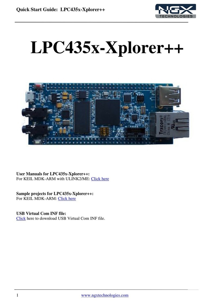
NGX Technologies
NGX Technologies LPC435x-Xplorer++ User manual
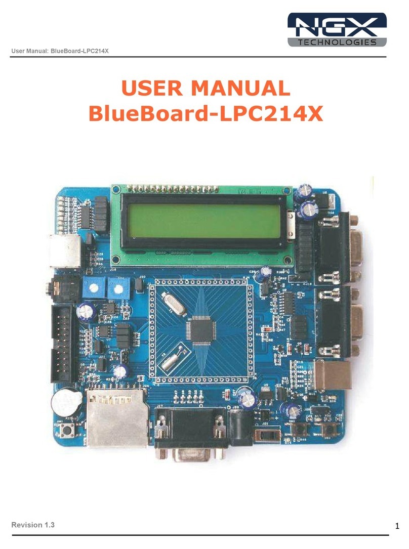
NGX Technologies
NGX Technologies BlueBoard-LPC214X User manual
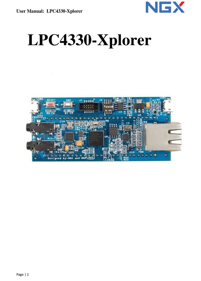
NGX Technologies
NGX Technologies LPC4330-Xplorer User manual
NGX Technologies
NGX Technologies LPC1768-Xplorer User manual

NGX Technologies
NGX Technologies BlueBoard Base User manual
NGX Technologies
NGX Technologies BlueBoard-LPC11U24/37 User manual

NGX Technologies
NGX Technologies LPC435x-Xplorer++ User manual
NGX Technologies
NGX Technologies LPC435x User manual
NGX Technologies
NGX Technologies LPC1788 Xplorer++ User manual
NGX Technologies
NGX Technologies LPC1830-Xplorer User manual
