NI cRIO-9081 User manual

-~
ARTISAN
®
~I
TECHNOLOGY
GROUP
Your definitive source
for
quality
pre-owned
equipment.
Artisan Technology
Group
Full-service,
independent
repair
center
with
experienced
engineers
and
technicians
on staff.
We
buy
your
excess,
underutilized,
and
idle
equipment
along
with
credit
for
buybacks
and
trade-ins
.
Custom
engineering
so
your
equipment
works
exactly as
you
specify.
•
Critical
and
expedited
services
•
Leasing
/
Rentals/
Demos
• In
stock/
Ready-to-ship
•
!TAR-certified
secure
asset
solutions
Expert
team
ITrust
guarantee
I
100%
satisfaction
All
tr
ademarks,
br
a
nd
names, a
nd
br
a
nd
s a
pp
earing here
in
are
th
e property of
th
e
ir
r
es
pecti
ve
ow
ner
s.
Visit our website - Click HERE

cRIO-9081
Getting Started
2022-07-15

Contents
Overview. . . . . . . . . . . . . . . . . . . . . . . . . . . . . . . . . . . . . . . . . . . . . . . . . . . . . . . . . . . . . . . . . . . . . . 3
Safety Guidelines. . . . . . . . . . . . . . . . . . . . . . . . . . . . . . . . . . . . . . . . . . . . . . . . . . . . . . . . . . . . 3
Safety Guidelines for Hazardous Locations. . . . . . . . . . . . . . . . . . . . . . . . . . . . . . . . 3
Electromagnetic Compatibility Guidelines. . . . . . . . . . . . . . . . . . . . . . . . . . . . . . . . . . . . . . 5
Special Conditions for Marine Applications. . . . . . . . . . . . . . . . . . . . . . . . . . . . . . . . 5
Preparing the Environment. . . . . . . . . . . . . . . . . . . . . . . . . . . . . . . . . . . . . . . . . . . . . . . . . . . 6
Unpacking the Kit. . . . . . . . . . . . . . . . . . . . . . . . . . . . . . . . . . . . . . . . . . . . . . . . . . . . . . . . . . . . 6
Verifying the Kit Contents. . . . . . . . . . . . . . . . . . . . . . . . . . . . . . . . . . . . . . . . . . . . . . . . . . . . . 7
Installing Soware on the Host Computer. . . . . . . . . . . . . . . . . . . . . . . . . . . . . . . . . . . . . . 7
Installing C Series Modules. . . . . . . . . . . . . . . . . . . . . . . . . . . . . . . . . . . . . . . . . . . . . . . . . . . . 7
Removing C Series Modules. . . . . . . . . . . . . . . . . . . . . . . . . . . . . . . . . . . . . . . . . . . . . . 8
Connecting the cRIO-9081. . . . . . . . . . . . . . . . . . . . . . . . . . . . . . . . . . . . . . . . . . . . . . . . . . . . 8
Connecting the cRIO-9081 to Ground. . . . . . . . . . . . . . . . . . . . . . . . . . . . . . . . . . . . . 8
Connecting the cRIO-9081 to Power. . . . . . . . . . . . . . . . . . . . . . . . . . . . . . . . . . . . . . . 9
Connecting the cRIO-9081 to a Network. . . . . . . . . . . . . . . . . . . . . . . . . . . . . . . . . . 12
Configuring IP Settings and Installing LabVIEW Real-Time Soware. . . . . . . . . . . . . . 12
System Reset Options. . . . . . . . . . . . . . . . . . . . . . . . . . . . . . . . . . . . . . . . . . . . . . . . . . 14
Troubleshooting the cRIO-9081. . . . . . . . . . . . . . . . . . . . . . . . . . . . . . . . . . . . . . . . . . . . . . 14
Troubleshooting Network Communication for LabVIEW Real-Time Systems. . 14
STATUS LED Indicators. . . . . . . . . . . . . . . . . . . . . . . . . . . . . . . . . . . . . . . . . . . . . . . . . 15
Where to Go Next. . . . . . . . . . . . . . . . . . . . . . . . . . . . . . . . . . . . . . . . . . . . . . . . . . . . . . . . . . . 16
NI Services. . . . . . . . . . . . . . . . . . . . . . . . . . . . . . . . . . . . . . . . . . . . . . . . . . . . . . . . . . . . . . . . . 17
ni.com
2
cRIO-9081 Getting Started

Overview
This document describes how to begin using the NI cRIO-9081.
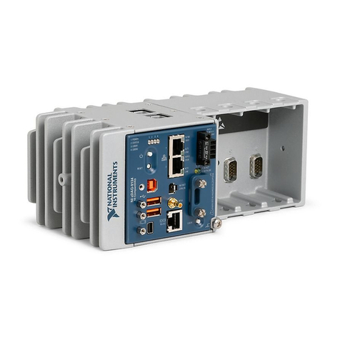
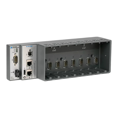
NI cRIO-9081
Safety Guidelines
Caution Observe all instructions and cautions in the user documentation.
Using the model in a manner not specified can damage the model and
compromise the built-in safety protection. Return damaged models to NI
for repair.
Attention Suivez toutes les instructions et respectez toutes les mises
en garde de la documentation utilisateur. L'utilisation d'un modèle de
toute autre façon que celle spécifiée risque de l'endommager et de
compromettre la protection de sécurité intégrée. Renvoyez les modèles
endommagés à NI pour réparation.
© National Instruments 3
cRIO-9081 Getting Started

Safety Guidelines for Hazardous Locations
The cRIO-9081 is suitable for use in Class I, Division 2, Groups A, B, C, D, T4
hazardous locations; Class I, Zone 2, AEx nA IIC T4 Gc and Ex nA IIC T4 Gc hazardous
locations; and nonhazardous locations only. Follow these guidelines if you are
installing the cRIO-9081 in a potentially explosive environment. Not following these
guidelines may result in serious injury or death.
Caution Do not disconnect the power supply wires and connectors from
the controller unless power has been switched o.
Caution Do not disconnect I/O-side wires or connectors unless power has
been switched o or the area is known to be nonhazardous.
Caution Do not remove modules unless power has been switched o or
the area is known to be nonhazardous.
Caution Substitution of components may impair suitability for Class I,
Division 2, or Zone 2.
Caution The system must be installed in an enclosure certified for the
intended hazardous (classified) location, having a tool secured cover/door,
where a minimum protection of at least IP54 is provided.
Special Conditions for Hazardous Locations Use in Europe and
Internationally
The cRIO-9081 has been evaluated as Ex nA IIC T4 Gc equipment under
DEMKO 07ATEX 0626664X and is IECEx UL 14.0089X certified. Each device is marked
II 3G and is suitable for use in Zone 2 hazardous locations, in ambient
temperatures of 0 °C ≤ Ta ≤ 55 °C.
ni.com
4
cRIO-9081 Getting Started

Caution Transient protection shall be provided that is set at a level not
exceeding 140% of the peak rated voltage value of 85 V at the supply
terminals to the equipment.
Caution The system shall only be used in an area of not more than
Pollution Degree 2, as defined in IEC/EN 60664-1.
Caution The system shall be mounted in an ATEX/IECEx-certified
enclosure with a minimum ingress protection rating of at least IP54 as
defined in IEC/EN 60079-15.
Caution The enclosure must have a door or cover accessible only by the
use of a tool.
Electromagnetic Compatibility Guidelines
This product was tested and complies with the regulatory requirements and limits
for electromagnetic compatibility (EMC) stated in the product specifications. These
requirements and limits provide reasonable protection against harmful interference
when the product is operated in the intended operational electromagnetic
environment.
This product is intended for use in industrial locations. However, harmful
interference may occur in some installations, when the product is connected to a
peripheral device or test object, or if the product is used in residential or
commercial areas. To minimize interference with radio and television reception and
prevent unacceptable performance degradation, install and use this product in strict
accordance with the instructions in the product documentation.
Furthermore, any changes or modifications to the product not expressly approved
by National Instruments could void your authority to operate it under your local
regulatory rules.
© National Instruments 5
cRIO-9081 Getting Started

Special Conditions for Marine Applications
Some products are approved for marine (shipboard) applications. To verify marine
approval certification for a product, visit ni.com/product-certifications, search by
model number, and click the appropriate link.
Notice In order to meet the EMC requirements for marine applications,
install the product in a shielded enclosure with shielded and/or filtered
power and input/output ports. In addition, take precautions when
designing, selecting, and installing measurement probes and cables to
ensure that the desired EMC performance is attained.
Preparing the Environment
Ensure that the environment in which you are using the cRIO-9081 meets the
following specifications.
Operating temperature (IEC 60068-2-1, IEC 60068-2-2) 0 °C to 55 °C
Operating humidity (IEC 60068-2-78) 10% RH to 90% RH, noncondensing
Pollution Degree 2
Maximum altitude 2,000 m
Indoor use only.
Note Refer to the device specifications on ni.com/manuals for complete
specifications.
Unpacking the Kit
Notice To prevent electrostatic discharge (ESD) from damaging the
device, ground yourself using a grounding strap or by holding a grounded
object, such as your computer chassis.
ni.com
6
cRIO-9081 Getting Started

1. Touch the antistatic package to a metal part of the computer chassis.
2. Remove the device from the package and inspect the device for loose
components or any other sign of damage.
Notice Never touch the exposed pins of connectors.
Note Do not install a device if it appears damaged in any way.
3. Unpack any other items and documentation from the kit.
Store the device in the antistatic package when the device is not in use.
Verifying the Kit Contents
Verify that the following items are included in the cRIO-9081 kit.
Installing Soware on the Host Computer
Before using the cRIO-9081, you must install the following application soware and
device drivers on the host computer in this order:
1. LabVIEW 2011 or later
2. LabVIEW Real-Time Module 2011 or later
3. LabVIEW FPGA Module 2011 or later[1]
4. NI CompactRIO Device Drivers 4.0 or later
For minimum soware support information, visit ni.com/info and enter the Info
Code swsupport.
1 LabVIEW FPGA Module is not required when using Scan Interface mode. To
program the user-accessible FPGA on the cRIO-9081, LabVIEW FPGA Module is
required.
Installing C Series Modules
Complete the following steps to install a C Series module.
© National Instruments 7
cRIO-9081 Getting Started

NI cRIO-9081
1. Verify that power is not connected to the I/O connector(s) on the C Series
module. If the system is in a nonhazardous location, the cRIO-9081 can be
powered on when you install modules.
2. Press the latches on the C Series module.
3. Align the C Series module with a slot and seat it in the slot until the latches
lock in place.
Removing C Series Modules
Verify that power is not connected to the I/O connector(s) on the C Series module
before you remove a module from the cRIO-9081. If the system is in a nonhazardous
location, the cRIO-9081 can be powered on when you remove modules.
Connecting the cRIO-9081
The cRIO-9081 has the following connectors, LEDs, and buttons.
Connecting the cRIO-9081 to Ground
You must connect the cRIO-9081 grounding terminal to the grounding electrode
system of the facility.
ni.com
8
cRIO-9081 Getting Started

What to Use
■Ring lug
■Wire, 1.6 mm2 (14 AWG) or larger
■Screwdriver, Phillips #2
What to Do
Complete the following steps to ground the cRIO-9081.
1. Attach the ring lug to the wire.
2. Remove the grounding screw from the grounding terminal on the cRIO-9081.
3. Attach the ring lug to the grounding terminal.
4. Tighten the grounding screw to 0.5 N · m (4.4 lb · in.) of torque.
5. Attach the other end of the wire to the grounding electrode system of your
facility using a method that is appropriate for your application.
Caution If you use shielded cabling to connect to a C Series module with
a plastic connector, you must attach the cable shield to the chassis
grounding terminal using 1.6 mm2 (14 AWG) or larger wire. Attach a ring
lug to the wire and attach the wire to the chassis grounding terminal.
Solder the other end of the wire to the cable shield. Use shorter wire for
better EMC performance.
For more information about ground connections, visit ni.com/info and enter the
Info Code emcground.
Connecting the cRIO-9081 to Power
The cRIO-9081 requires a 9 V to 30 V external power supply. The cRIO-9081 filters
and regulates the supplied power and provides power for the C Series modules. The
cRIO-9081 has a primary power input, V1, and a secondary power input, V2.
© National Instruments 9
cRIO-9081 Getting Started

The POWER LED on the cRIO-9081 indicates which power input is in use, as shown in
the following table.
LED Color LED Pattern Indication
Green Solid The cRIO-9081 is powered from the V1 input.
Yellow Solid The cRIO-9081 is powered from the V2 input.
—O The cRIO-9081 is powered o.
Table 1. POWER LED Indicators
Caution Do not connect V2 to a DC mains supply or to any supply that
requires a connecting cable longer than 3 m(10 ). A DC mains supply is a
local DC electricity supply network in the infrastructure of a site or
building.
What to Use
■Ferrite
■Screwdriver, 2.54 mm (0.10 in.) flathead
■Primary power supply, 9 V to 30 V, 46 W minimum
■(Optional) Secondary power supply, 9 V to 30 V, 46 W minimum
NI recommends the power supplies listed in the following table for the cRIO-9081.
Power Supply Part Number
NI PS-15 Industrial Power Supply (24 V DC, 5 A, 100 V AC to 120 V AC/200 V AC to
240 V AC input)
781093-01
NI PS-10 Desktop Power Supply (24 V DC, 5 A, 100 V AC to 120 V AC/200 V AC to
240 V AC input)
782698-01
Table 2. NI Power Supplies
What to Do
Complete the following steps to connect a power supply to the cRIO-9081.
1. Ensure that your power supply is powered o.
ni.com
10
cRIO-9081 Getting Started

2. Install the ferrite on the negative and positive leads of the power supply, as
shown in the following figure.
Figure 1. Installing a Ferrite on the Power Leads
2
1
1. Pass the leads through the ferrite twice, leaving 50 mm to 75 mm (2 in.
to 3 in.) between the ferrite and the end of the leads.
2. Close the ferrite around the leads.
3. Remove the power connector from the cRIO-9081.
Caution Do not tighten or loosen the terminal screws on the power
connector while the cRIO-9081 is powered on.
4. Connect the primary power supply and optional secondary power supply to
the power connector.
Note The C terminals are internally connected to each other.
5. Tighten the terminal screws on the power connector to 0.20 N · m to 0.25 N · m
(1.8 lb · in. to 2.2 lb · in.) of torque.
6. Install the power connector on the front panel of the cRIO-9081.
7. Tighten the power connector screw flanges to 0.20 N · m to 0.25 N · m
(1.8 lb · in. to 2.2 lb · in.) of torque.
8. Power on the primary power supply and optional secondary power supply.
Powering On the cRIO-9081
To power on the cRIO-9081, ensure that the power source is turned on and press the
power button on the front panel of the cRIO-9081. You can use the cRIO-9081 BIOS
setup utility to configure the cRIO-9081 to start immediately when power is applied
or to respond to the front-panel power button. Refer to the device user manual on
© National Instruments 11
cRIO-9081 Getting Started

ni.com/manuals for information about the dierent powerup behaviors you can
configure. The power button is enabled by default so that the cRIO-9081 does not
power on until the power button is pressed. When the cRIO-9081 powers on, the
Power LED turns on and the controller runs a power-on self test (POST).
When the POST is complete, the operating system is loaded and the cRIO-9081 is
ready for use. The cRIO-9081 as shipped either includes a pre-installed operating
system such as Windows, or has the hard drive partitioned for LabVIEW Real-Time.
In order for the system to boot into LabVIEW Real-Time, the DISABLE RT DIP switch
must be in the OFF position. In order for the system to boot into any other operating
system, the DISABLE RT DIP switch must be in the ON position. Refer to the device
user manual on ni.com/manuals for more information about the DIP switches.
Connecting the cRIO-9081 to a Network
Connect the cRIO-9081 to an Ethernet network using RJ-45 Ethernet port 1 on the
controller front panel. Use a standard Category 5 (CAT-5) or better shielded, twisted-
pair Ethernet cable to connect the cRIO-9081.
Note To prevent data loss and to maintain the integrity of your Ethernet
installation, do not use a cable longer than 100 m.
For Windows systems, the network behavior is determined by the Windows network
drivers.
For RT systems, the cRIO-9081 attempts to initiate a DHCP network connection at
powerup. If the cRIO-9081 is unable to obtain an IP address, it connects to the
network with a link-local IP address with the form 169.254.x.x.
Aer powerup, you can install soware on the cRIO-9081. For RT systems, you can
also change the network settings using Measurement & Automation Explorer (MAX)
on a host computer.
Note Installing soware may change the network behavior of the
cRIO-9081. For information about network behavior by installed soware
version, go to ni.com/info and enter the Info Code ipconfigcrio.
The host computer communicates with the cRIO-9081 over a standard Ethernet
connection.
ni.com
12
cRIO-9081 Getting Started

Configuring IP Settings and Installing LabVIEW Real-Time
Soware
This section describes how to configure IP settings and install LabVIEW Real-Time
soware on the cRIO-908x. If your system has a version of Windows installed on it,
refer to the Windows documentation for information about configuring IP settings.
Systems shipped with Windows pre-installed also have a compatible version of the
NI-RIO soware pre-installed.
When you power on the controller for the first time, it boots into safe mode if there
is no soware installed on it. Complete the following steps to configure IP settings
and install soware.
1. Power on the system with the DISABLE RT DIP switch in the OFF position.
2. Launch MAX on the host computer and expand Remote Systems in the MAX
configuration tree. MAX lists the cRIO controller as the model name of the
controller followed by the MAC address, for example, NI-
cRIO-908100802f108562.
The controller automatically attempts to connect to the network using DHCP.
If the controller is unable to obtain an IP address, it connects to the network
with a link-local IP address with the form 169.254.x.x.
3. Enter a name for the Real-Time target in the Name field in the System Settings
tab.
4. Select the controller under Remote Systems to see the Network Settings tab in
the middle pane of MAX.
5. Select settings for the Real-Time target in the IP Settings section, then click
Apply.
Note For information about configuring network settings, refer to
the Configuring Network Settings book of the MAX Remote
Systems Help. In MAX, click Help » Help Topics » Remote Systems.
On the Contents tab, browse to LabVIEW Real-Time Target
Configuration » Configuring Network Settings.
© National Instruments 13
cRIO-9081 Getting Started
6. When you click Apply, you are prompted to reboot the controller for the
changes to take eect. Click Yes. You can also reboot the controller by right-
clicking the name under Remote Systems and selecting Reboot.
7. Aer rebooting, the controller appears under Remote Systems with the
assigned name. Expand the controller and select Software.
8. Click Add/Remove Software in the toolbar to launch the LabVIEW Real-Time
Soware Wizard.
9. Install LabVIEW Real-Time soware and device drivers on the controller.
Aer soware installation, the controller automatically reboots. You can now
program it using LabVIEW Real-Time. For information about configuring the
controller to launch an embedded stand-alone application at startup, refer to the
LabVIEW Help.
System Reset Options
The following table lists the reset options available on the cRIO-9081. These options
determine how the system behaves when the controller is reset in various
conditions. Use the RIO Device Setup utility to select reset options. Launch the RIO
Device Setup utility by selecting Start » All Programs » National Instruments » NI-
RIO » RIO Device Setup.
Chassis Reset Option Behavior
Do not autoload VI Does not load the FPGA bit stream from flash memory.
Autoload VI on device
powerup
Loads the FPGA bit stream from flash memory to the FPGA when
the controller powers on.
Autoload VI on device reboot Loads the FPGA bit stream from flash memory to the FPGA when
you reboot the controller either with or without cycling power.
Table 3. cRIO-9081 Reset Options
Troubleshooting the cRIO-9081
ni.com
14
cRIO-9081 Getting Started
Troubleshooting Network Communication for LabVIEW Real-Time
Systems
If the controller cannot communicate with the network, you can use the IP RESET
switch to manually restore the controller to the default network settings. When you
reboot the controller with the IP RESET switch in the ON position, the controller
attempts to connect to the network using DHCP. If the controller is unable to obtain
an IP address, it connects to the network with a link-local IP address with the form
169.254.x.x.
Complete the following steps to restore the controller to the default network
settings.
1. Move the IP RESET switch to the ON position.
2. Push the RESET button to cycle power to the chassis.
3. Configure the IP and other network settings in MAX from the host computer.
4. Move the IP RESET switch to the OFF position.
For more information about troubleshooting network communication, go to ni.com/
info and enter the Info Code rdcriostartup.
STATUS LED Indicators
The STATUS LED is o during normal operation. The cRIO-9081 indicates specific
soware error conditions by flashing the STATUS LED yellow a certain number of
times every few seconds, as shown in the following table.
Number of Yellow
Flashes Every Few
Seconds
Indication
1 The chassis is unconfigured. Use MAX to configure the chassis. Refer to the
Measurement & Automation Explorer Help for information about
configuring the chassis.
2 The chassis has detected an error in its soware. This usually occurs when an
attempt to upgrade the soware is interrupted. Reinstall soware on the
chassis. Refer to the Measurement & Automation Explorer Help for
information about installing soware on the chassis.
© National Instruments 15
cRIO-9081 Getting Started

Number of Yellow
Flashes Every Few
Seconds
Indication
3 The chassis is in safe mode because the SAFE MODE DIP switch is in the ON
position or there is no soware installed on the chassis.
4 The soware has crashed twice without rebooting or cycling power between
crashes. This usually occurs when the chassis runs out of memory. Review
your RT VI and check the memory usage. Modify the VI as necessary to solve
the memory usage issue.
Continuously
Flashing
The chassis has detected an unrecoverable error. Contact National
Instruments.
Continuously
Flashing or Solid
The device may be configured for DHCP but unable to get an IP address
because of a problem with the DHCP server. Check the network connection
and try again. If the problem persists, contact National Instruments.
Table 4. STATUS LED Soware Indicators
The cRIO-9081 indicates specific hardware error conditions by flashing the STATUS
LED red a certain number of times every few seconds, as shown in the following
table.
Pattern of Red
Flashes
Indication
Continuously
Flashing
An internal power supply has failed. Check front-panel I/O, CXM, and C
Series module connections for shorts. Remove any shorts and power cycle
the controller. If the problem persists, contact National Instruments.
Solid The cRIO-9081 internal temperature has exceeded a critical threshold. If
the problem persists, contact National Instruments.
Table 5. STATUS LED Hardware Indicators
Where to Go Next
ni.com
16
cRIO-9081 Getting Started
NI CompactRIO
Developer’s Guide
ni.com/compactriodevguide
CompactRIO Sample
Projects
LabVIEW » Create Project
NI cRIO-9081 Specifications
ni.com/manuals
NI cRIO-9081 User Manual
ni.com/manuals
C Series Getting
Started Guides
ni.com/manuals
HARDWARE SOFTWARE APPLICATION
SUPPORT
Services
ni.com/services
Community
ni.com/community
Software Support
ni.com/info » swsupport
Configuring a Project
NI-RIO Help
Learn LabVIEW Basics
ni.com/gettingstarted
CompactRIO Examples
NI Example Finder
Support
ni.com/support
NI Services
Visit ni.com/support to find support resources including documentation,
downloads, and troubleshooting and application development self-help such as
tutorials and examples.
Visit ni.com/services to learn about NI service oerings such as calibration options,
repair, and replacement.
Visit ni.com/register to register your NI product. Product registration facilitates
technical support and ensures that you receive important information updates from
NI.
NI corporate headquarters is located at 11500 N Mopac Expwy, Austin, TX,
78759-3504, USA.
© National Instruments 17
cRIO-9081 Getting Started
© 2022 National Instruments Corporation.

Artisan
Technology
Group
is
an independent supplier
of
quality pre-owned equipment
Gold-standard
solutions
Extend the life
of
your
critical industrial,
commercial, and military systems
with
our
superior service and support.
We
buy
equipment
Planning to
upgrade
your current
equipment? Have surplus equipment taking
up shelf space? We'll give it a
new
home.
Learn
more!
Visit us at artisantg.com for more info
on price quotes, drivers, technical
specifications, manuals, and documentation.
Artisan Scientific
Corporation
dba
Artisan
Technology
Group
is
not
an affiliate,
representative,
or
authorized
distributor
for
any
manufacturer
listed herein.
We're here to make your life easier.
How
can
we
help you today?
(217)
352-9330
Isales@artisantg.com Iartisantg.com
Table of contents
Other NI Controllers manuals
Popular Controllers manuals by other brands

Weidmüller
Weidmüller UC20-SL2000-EC-CAN manual

Honeywell
Honeywell CIPer 30 Installation and operation guide

Siemens
Siemens GBB 1E Series Mounting instructions

ABB
ABB DOL Starter installation instructions

Linear Technology
Linear Technology LTC3618EUF Demo Manual

Rev-A-Shelf
Rev-A-Shelf Tresco Lighting FREEDiM L-WLD-RGB-WH-1 installation instructions