NI PXIe-5114 User manual

GETTING STARTED GUIDE
NI PXI/PXIe/PCI-5114
8-Bit 250 MS/s Oscilloscope
This document explains how to install, configure, and test the NI PXI/PXIe/PCI-5114
(NI 5114). The NI 5114 is a 2-channel, 125 MHz oscilloscope. The NI 5114 ships with the
NI-SCOPE instrument driver, which you use to program the device.
Note Before you begin, install and configure your chassis and controller.
To access NI 5114 documentation, navigate to Start»All Programs»National Instruments»
NI-SCOPE»Documentation.
Contents
Safety and Electromagnetic Compatibility............................................................................... 2
Verifying the System Requirements..........................................................................................2
Unpacking the Kit..................................................................................................................... 2
Preparing the Environment....................................................................................................... 3
PXI Express Modules........................................................................................................3
PXI Modules..................................................................................................................... 3
PCI Modules..................................................................................................................... 3
Kit Contents.............................................................................................................................. 4
Other Equipment............................................................................................................... 5
Installing the Software.............................................................................................................. 5
Installing the Hardware.............................................................................................................5
Installing the NI PXI/PXIe-5114.......................................................................................5
Installing the NI PCI-5114................................................................................................ 7
Hardware Front Panel Connectors.................................................................................... 8
Configuring the Hardware in MAX.......................................................................................... 9
Programming the NI 5114.......................................................................................................10
NI-SCOPE Examples...................................................................................................... 11
Making a Measurement...........................................................................................................11
Making a Measurement with NI-SCOPE SFP................................................................ 11
Making a Measurement with LabVIEW......................................................................... 11
Setting Up SMC-Based Devices for Synchronization............................................................ 12
PXI Modules................................................................................................................... 12
PXI Express Modules......................................................................................................12
PCI Devices.....................................................................................................................12
Troubleshooting...................................................................................................................... 13
Why Is the ACCESS LED Off When the Chassis is On?...............................................13
NI 5114 Does Not Appear in MAX................................................................................ 13

What Should I Do if the Module Fails the Self-Test?.....................................................14
Thermal Shutdown Error................................................................................................ 14
Where to Go Next................................................................................................................... 14
Worldwide Support and Services............................................................................................ 15
Safety and Electromagnetic Compatibility
Caution Refer to the Read Me First: Safety and Electromagnetic Compatibility
document for important safety and electromagnetic compatibility information. To
obtain a copy of this document online, visit ni.com/manuals and search for the
document title.
For additional electromagnetic compatibility information, including any product-specific
installation or configuration requirements necessary to achieve the specified level of
electromagnetic compatibility performance, refer to the individual product specifications.
Verifying the System Requirements
To use the NI 5114, your system must meet certain requirements.
For more information about minimum system requirements, recommended system
requirements, and supported ADEs, refer to the readme for your selected software support.
Readmes are available on the driver software DVD and online at ni.com/updates.
Unpacking the Kit
Caution To prevent electrostatic discharge from damaging the device, ground
yourself using a grounding strap or by holding a grounded object, such as your
computer chassis.
1. Touch the antistatic package to a metal part of the computer chassis.
2. Remove the device from the package and inspect the device for loose components or any
other sign of damage.
Caution Never touch the exposed pins of connectors.
Notify NI if the device appears damaged in any way. Do not install a damaged device.
3. Unpack any other items and documentation from the kit.
Store the device in the antistatic package when the device is not in use.
2| ni.com | NI PXI/PXIe/PCI-5114 Getting Started Guide

Preparing the Environment
Ensure that the environment in which you are using the NI 5114 meets the following
specifications:
PXI Express Modules
Operating Environment
....................................................................Ambient temperature range 0 °C to 55 °C (Tested in accordance with
IEC-60068-2-1 and IEC-60068-2-2. Meets
MIL-PRF-28800F Class 3 low temperature
limit and MIL-PRF-28800F Class 2 high
temperature limit.)
....................................................................Relative humidity range 10% to 90%, noncondensing (Tested in
accordance with IEC-60068-2-56.)
............................................................................Maximum altitude 2,000 m (800 mbar) (at 25 °C ambient
temperature)
............................................................................Pollution Degree 2
Indoor use only.
PXI Modules
Operating Environment
....................................................................Ambient temperature range 0 °C to 55 °C (Tested in accordance with
IEC-60068-2-1 and IEC-60068-2-2.)
....................................................................Relative humidity range 10% to 90%, noncondensing (Tested in
accordance with IEC-60068-2-56.)
............................................................................Maximum altitude 2,000 m (at 25 °C ambient temperature)
............................................................................Pollution Degree 2
Indoor use only.
PCI Modules
Operating Environment
....................................................................Ambient temperature range 0 °C to 45 °C (Tested in accordance with
IEC-60068-2-1 and IEC-60068-2-2.)
....................................................................Relative humidity range 10% to 90%, noncondensing (Tested in
accordance with IEC-60068-2-56.)
NI PXI/PXIe/PCI-5114 Getting Started Guide | © National Instruments | 3
............................................................................Maximum altitude 2,000 m (at 25 °C ambient temperature)
............................................................................Pollution Degree 2
Indoor use only.
Caution Clean the hardware with a soft, nonmetallic brush. Make sure that the
hardware is completely dry and free from contaminants before returning it to
service.
For complete specifications, refer to specifications document for your device at ni.com/
manuals.
Kit Contents
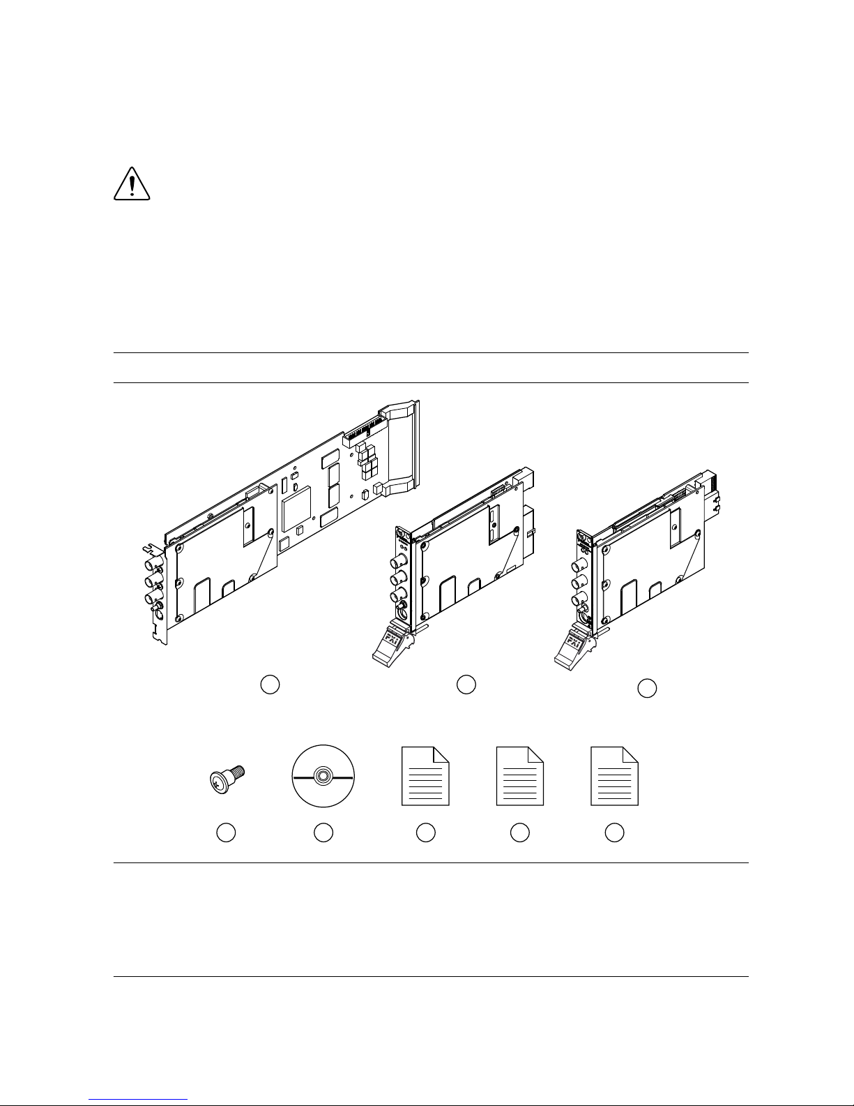
Figure 1. NI 5114 Kit Contents
123
5 6 7 8
4
1. NI PCI-5114 Device
2. NI PXI-5114 Device
3. NI PXIe-5114 Device
4. Screw Kit, part number 191306A-01 (ships only
with PCI kit)
5. Driver Software DVD
6. NI PXI/PXIe/PCI-5114 Getting Started Guide (this
document)
7. Read Me First: Safety and Electromagnetic
Compatibility
8. Maintain Forced-Air Cooling Note to Users
4| ni.com | NI PXI/PXIe/PCI-5114 Getting Started Guide

Other Equipment
There are several required items not included in your device kit that you need to install or
operate the NI 5114.
•(PXI Express Devices) A PXI Express chassis with a controller and the chassis
documentation
•(PXI Devices) A PXI chassis, a PXI/SCXI combination chassis, or a PXI/CompactPCI
chassis with a controller and the chassis documentation
•(PCI Devices) A desktop computer and its documentation
Note If your application uses NI-TClk synchronization for PCI devices, you must
use a RTSI cable to connect the PCI devices. For more information, refer to NI
High-Speed Digitizers Help»Programming»Reference»NI-TClk
Synchronization Help.
Installing the Software
You must be an Administrator to install NI software on your computer.
1. Install an ADE, such as LabVIEW or LabWindows™/CVI™.
2. Insert the driver software media into your computer. The installer should open
automatically.
If the installation window does not appear, navigate to the drive, double-click it, and
double-click autorun.exe.
3. Follow the instructions in the installation prompts.
Note Windows users may see access and security messages during
installation. Accept the prompts to complete the installation.
4. When the installer completes, select Restart in the dialog box that prompts you to restart,
shut down, or restart later.
Installing the Hardware
Installing the NI PXI/PXIe-5114
Caution To prevent damage to the device caused by ESD or contamination, handle
the device using the edges or the metal bracket.
1. Ensure the AC power source is connected to the chassis before installing the modules.
The AC power cord grounds the chassis and protects it from electrical damage while you
install the modules.
2. Power off the chassis.
3. Inspect the slot pins on the chassis backplane for any bends or damage prior to
installation. Do not install a module if the backplane is damaged.
NI PXI/PXIe/PCI-5114 Getting Started Guide | © National Instruments | 5
4. Remove the black plastic connectors from all the captive screws on the module front
panel.
5. Identify a supported slot in the chassis. The following figure shows the symbols that
indicate the slot types.
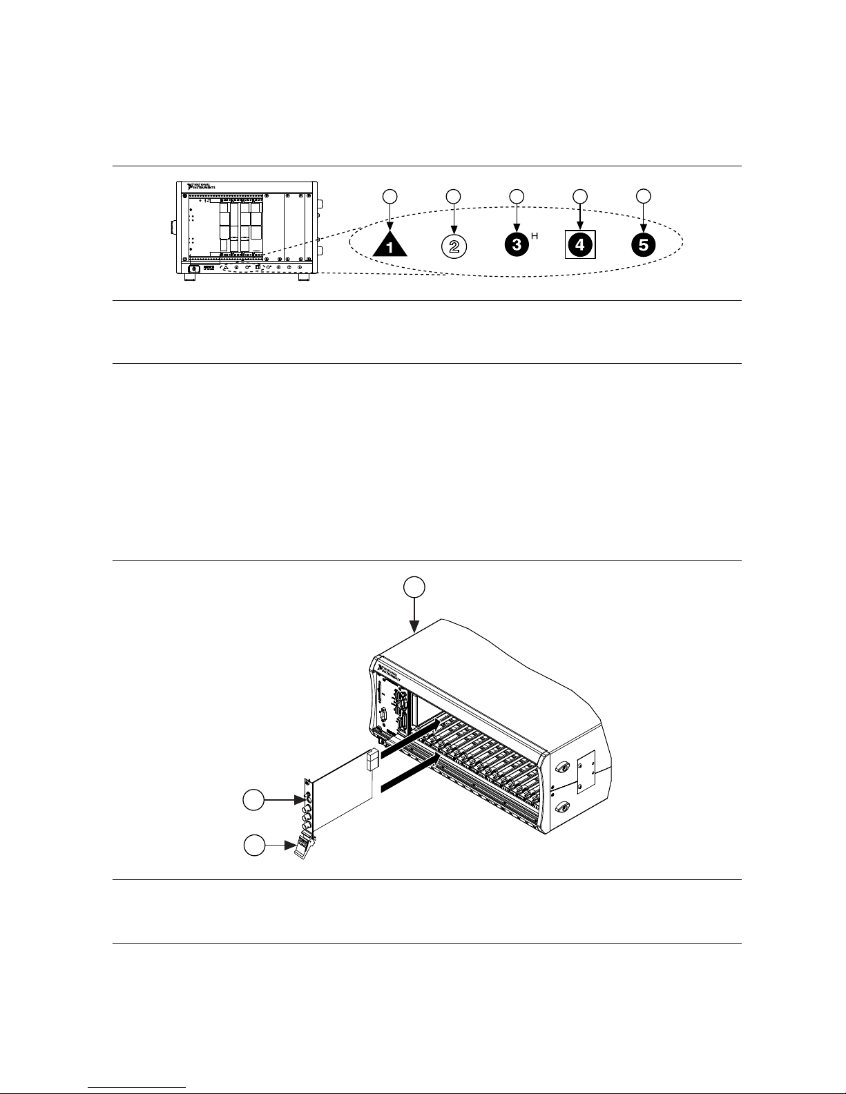
Figure 2. Chassis Compatibility Symbols
NI PXIe-1062Q
12 3 45
1. PXI Express System Controller Slot
2. PXI Peripheral Slot
3. PXI Express Hybrid Peripheral Slot
4. PXI Express System Timing Slot
5. PXI Express Peripheral Slot
PXI modules can be placed in PXI peripheral slots or PXI Express Hybrid peripheral
slots. PXI Express modules can be placed in PXI Express peripheral slots, PXI Express
Hybrid peripheral slots, or PXI Express System Timing slots.
6. Touch any metal part of the chassis to discharge static electricity.
7. Ensure that the ejector handle is in the unlatched (downward) position.
8. Place the module edges into the module guides at the top and bottom of the chassis. Slide
the device into the slot until it is fully inserted.
Figure 3. Module Installation
2
3
NI PXIe-1075
1
1. Chassis
2. Hardware Module
3. Ejector Handle in Down (Unlatched Position)
9. Latch the module in place by pulling up on the ejector handle.
10. Secure the device front panel to the chassis using the front-panel mounting screws.
6| ni.com | NI PXI/PXIe/PCI-5114 Getting Started Guide

11. Cover all empty slots using filler panels or slot blockers to maximize cooling air flow.
12. Power on the chassis.
Note For more information about maximizing cooling air flow, refer to the
Maintain Forced-Air Cooling Note to Users included in your kit.
Installing the NI PCI-5114
1. Power off and unplug the computer.
2. Access the computer system expansion slots. This step might require you to remove one
or more access panels on the computer case.
3. Locate a compatible slot and remove the corresponding slot cover on the computer back
panel. NI 5114 modules can be inserted only into PCI slots.
4. Touch any metal part of the computer to discharge any static electricity.
5. Insert the module into the slot you selected. Gently rock the module in to place without
forcing it.
Figure 4. Module Installation
1
2
3
1. Module
2. System Expansion Slot
3. PC
6. Secure the module mounting bracket to the computer back panel rail.
Caution It is important to completely screw the device into the slot, both for
mechanical stability and for creating a solid ground connection, which reduces
signal noise. Improperly secured devices may affect the accuracy of device
specifications.
7. Replace any access panels on the computer case.
8. Plug in and power on your computer.
NI PXI/PXIe/PCI-5114 Getting Started Guide | © National Instruments | 7
Hardware Front Panel Connectors
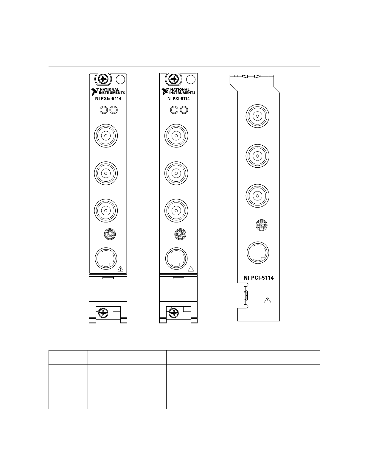
Refer to the following figure and table for the NI 5114 front panels and signal connectors.
Figure 5. NI 5114 Front Panels
TRIG
CH 0
CH 1
AUX I/O +5 V
MAX
CLK IN
TRIG
CH 0
125MHz Oscilloscope
ACCESS ACTIVE
CH 1
AUX
I/O
+5 V
MAX
CLK IN
TRIG
CH 0
ACCESS ACTIVE
CH 1
AUX
I/O
+5 V
MAX
CLK IN
125MHz Oscilloscope
Table 1. NI 5114 Front Panel Signal Connections
Connector Description Function
CH 0, CH 1 BNC female Analog input connection; digitizes data and triggers
acquisitions.
TRIG BNC female External analog trigger connection; signals on the
TRIG connector cannot be digitized.
8| ni.com | NI PXI/PXIe/PCI-5114 Getting Started Guide

Table 1. NI 5114 Front Panel Signal Connections (Continued)
Connector Description Function
CLK IN SMB jack Input for an external reference clock or sample
clock to the device.
AUX I/O 9-pin mini-circular DIN
connector
Provides access to the multipurpose digital timing
and triggering lines, PFI 0, PFI 1 (with optional
cable). For pinout information, refer to Figure 14.
Configuring the Hardware in MAX
Use Measurement & Automation Explorer (MAX) to configure your National Instruments
hardware. MAX informs other programs about which devices reside in the system and how
they are configured. MAX is automatically installed with NI-SCOPE .
1. Launch Measurement & Automation Explorer (MAX).
MAX should automatically detect the device you installed.
2. In the Configuration pane, double-click Devices and Interfaces to see the list of installed
devices. Installed devices appear under the name of their associated chassis.
3. Expand your Chassis tree item. MAX lists all devices installed in the chassis. Your
default device names may vary.
Note If you do not see your hardware listed, press <F5> to refresh the list of
installed devices. If the device is still not listed, power off the system, ensure
the device is correctly installed, and restart.
4. Record the device identifier MAX assigns to the hardware. Use this identifier when
programming the NI 5114.
5. The MAX self-test performs a basic verification of hardware resources. To self-test a
module in MAX, right click the module and select Self-Test.
6. Run the test panels on the device to verify the signal.
a) To access the test panels, right-click the device and select Test Panels. The
NI-SCOPE Soft Front Panel (SFP) launches automatically.
b) Do one of the following to connect a signal to the device:
• Connect an external signal by clicking Auto or by selecting the appropriate
device parameters for the signal.
• Connect a cable from PFI 1 to an input channel and select Utility»Probe
Compensation from the SFP menu.
Note The NI 5114 has self-calibration capabilities, which you can access
programmatically with NI-SCOPE and your ADE, or interactively with
NI-SCOPE SFP or MAX.
Related Information
Making a Measurement on page 11
NI PXI/PXIe/PCI-5114 Getting Started Guide | © National Instruments | 9

Programming the NI 5114
You can acquire data interactively using the NI-SCOPE SFP, or you can use the NI-SCOPE
instrument driver to program your device in the supported ADE of your choice.
Table 2. NI 5114 Programming Options
Application
Programming
Interface (API)
Location Description
NI-SCOPE SFP Available from the start menu at
Start»All Programs»National
Instruments»NI-SCOPE»NI-
SCOPE Soft Front Panel
The NI-SCOPE SFP acquires,
controls, analyzes, and presents
data, similar to stand-alone
oscilloscopes. The NI-SCOPE SFP
operates on the PC, so you can view
and control waveforms directly
from your computer. You can also
run multiple sessions of the
NI-SCOPE SFP simultaneously.
NI-SCOPE
Instrument Driver
LabVIEW—Available on the
LabVIEW Functions palette at
Measurement I/O»NI-SCOPE.
NI-SCOPE configures and operates
the device hardware and performs
basic waveform acquisition and
measurement options using
LabVIEW VIs or LabWindows/CVI
functions.
C or LabWindows/CVI—
Available at Program Files»IVI
Foundation»IVI»Drivers»
niScope.
Microsoft Visual C/C++—Use
examples located in the
<NIDocDir>\NI–SCOPE
\examples directory, where
<NIDocDir> is one of the
following directories:
• Windows 8/7/Vista—Users
\Public\Documents
\National
Instruments
• Windows XP—Documents
and Settings\All
Users\Shared
Documents\National
Instruments
You can modify an NI-SCOPE C
example to create an application
with Microsoft Visual C/C++. Copy
an NI-SCOPE example to copy
required project settings for include
paths and library files.
Alternatively, refer to the Creating
an Application with Microsoft
Visual C and C++ topic of the NI
High-Speed Digitizers Help to
manually add all required include
and library files to your project.
10 | ni.com | NI PXI/PXIe/PCI-5114 Getting Started Guide
This manual suits for next models
2
Table of contents
Other NI Test Equipment manuals


