NI PXIe-5170R Manual

CALIBRATION PROCEDURE
NI PXIe-5170R
This document contains the verification and adjustment procedures for the NI PXIe-5170R
(NI 5170R). Refer to ni.com/calibration for more information about calibration solutions.
Contents
Required Software.....................................................................................................................1
Related Documentation.............................................................................................................2
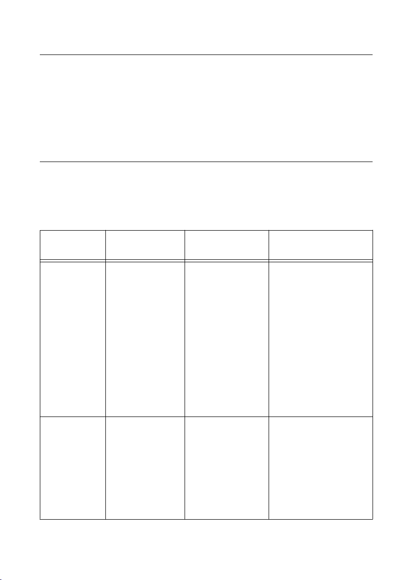
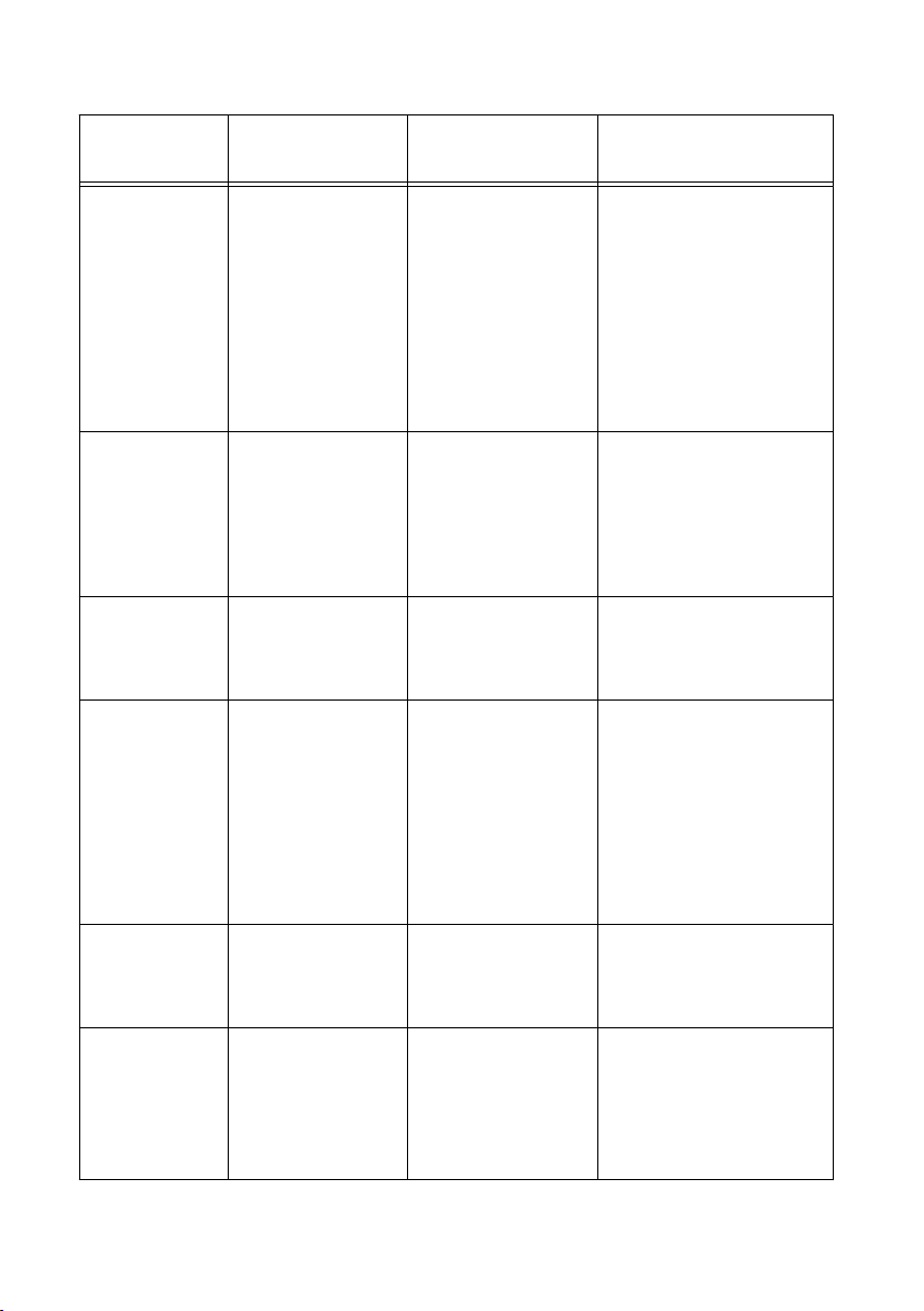
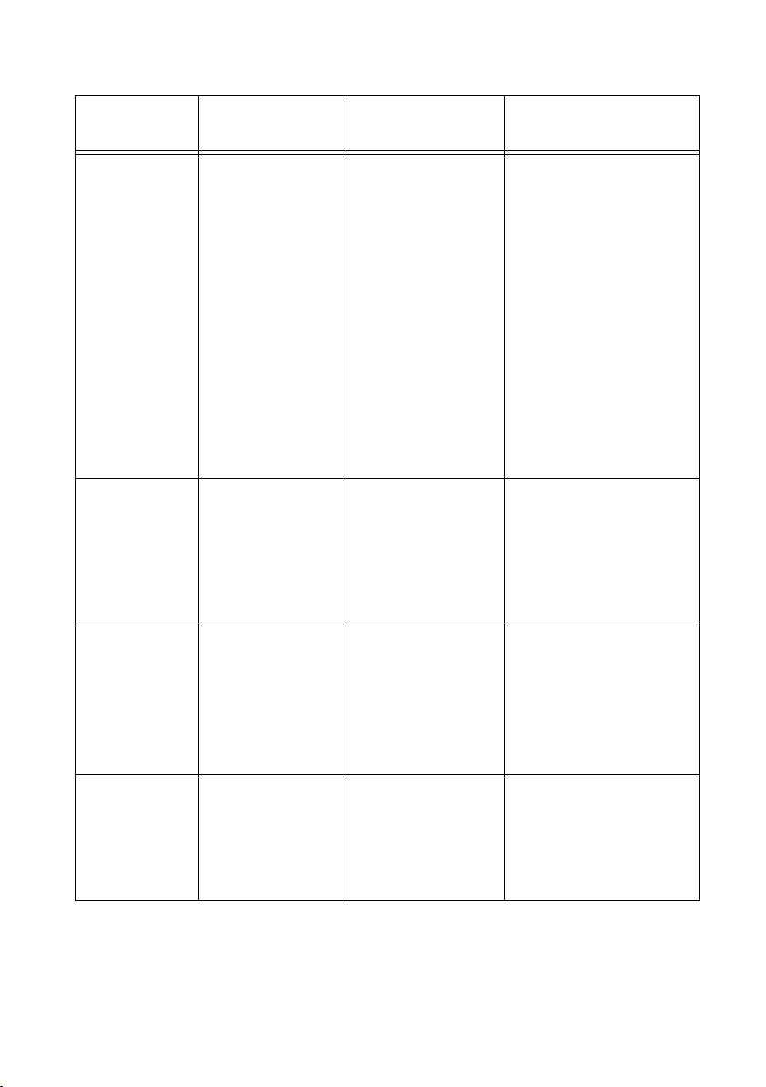
Test Equipment..........................................................................................................................2
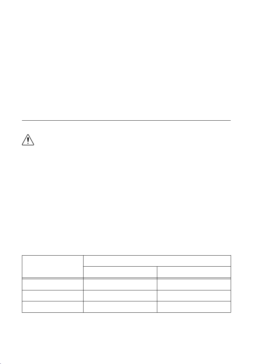
Test Conditions..........................................................................................................................5
Password................................................................................................................................... 6
Calibration Interval................................................................................................................... 6
As-Found and As-Left Limits................................................................................................... 6
Measurement Uncertainty......................................................................................................... 6
Calibration Overview................................................................................................................6
Test System Characterization....................................................................................................7
Zeroing the Power Sensor................................................................................................. 7
Characterizing Power Splitter Amplitude Imbalance....................................................... 7
Verification..............................................................................................................................10
Verifying Timebase Accuracy......................................................................................... 11
Verifying DC Accuracy...................................................................................................12
Verifying AC Amplitude Accuracy.................................................................................14
Verifying Flatness and Bandwidth.................................................................................. 18
Adjustment.............................................................................................................................. 21
Adjusting DC.................................................................................................................. 21
Adjusting Timebase.........................................................................................................22
Reverification..........................................................................................................................23
Updating Verification Date and Time..................................................................................... 23
Worldwide Support and Services............................................................................................ 23
Required Software
Calibrating the NI 5170R requires you to install the following software on the calibration
system:
• LabVIEW Instrument Design Libraries for Reconfigurable Oscilloscopes. The NI 5170R
was first supported in LabVIEW Instrument Design Libraries for Reconfigurable
Oscilloscopes 14.0.
You can download all required software from ni.com/downloads.

Related Documentation
You might find the following documents helpful as you perform the calibration procedure:
•NI PXIe-5170R Getting Started Guide
•NI Reconfigurable Oscilloscopes Help
•NI PXIe-5170R Specifications
The latest versions of these documents are available from ni.com/manuals.
Test Equipment
This section lists the equipment required to calibrate the NI 5170R.
If you do not have the recommended equipment, select a substitute calibration standard using
the specifications listed in the table.
Table 1. NI 5170R Test Equipment
Equipment Recommended
Model
Where Used Minimum Requirements
Oscilloscope
calibrator
Fluke 9500B/600
with Fluke 9530
Active Head
Verifications:
• Timebase
accuracy
• DC accuracy
Adjustments:
• Timebase
• DC
Sine Wave Amplitude:
0.9 Vpk-pk at 11 MHz into
50 Ω
Sine Wave Frequency
Accuracy: 0.25 ppm at
11 MHz
DC Output Range: ±40 mV
to ±2.5 V into 50 Ω
DC Output Accuracy:
±(0.025% of output +
25 µV) into 50 Ω
SMA (m)-to-
BNC (f) adapter
Fairview Microwave
SM4723
Verifications:
• Timebase
accuracy
• DC accuracy
Adjustments:
• Timebase
• DC
Frequency range: DC to
11 MHz
Impedance: 50 Ω
2| ni.com | NI PXIe-5170R Calibration Procedure

Table 1. NI 5170R Test Equipment (Continued)
Equipment Recommended
Model
Where Used Minimum Requirements
DMM NI PXI-4071 Verifications:
• AC amplitude
accuracy
AC voltage accuracy:
±0.1% of reading at 50 kHz
AC Input Range: 0.1 Vpk-pk
to 3.5 Vpk-pk
AC Input Impedance:
≥10 MΩ
Bandwidth: ≥100 kHz
Function
generator
NI PXI-5402 or
Agilent 33220A
Verifications:
• AC amplitude
accuracy
Sine Wave Frequency:
50 kHz
Sine Wave Amplitude
Range: 0.1 Vpk-pk to
3.5 Vpk-pk into 50 Ω
SMA Tee (f-f-f) Fairview Microwave
SM4942
Verifications:
• AC amplitude
accuracy
Impedance: 50 Ω
SMA (m)-to-
SMA (m)
adapter (x2)
Fairview Microwave
SM4960
Test system
characterization
Verifications:
• AC amplitude
accuracy
• Flatness and
bandwidth
Frequency range: DC to
275 MHz
VSWR: <1.05
Impedance: 50 Ω
Double banana
plug to BNC (f)
Pasternak PE9008 Verifications:
• AC amplitude
accuracy
Impedance: 50 Ω
SMA (m)-to-
BNC (m) cable
(x2)
— Verifications:
• AC amplitude
accuracy
Frequency range: DC to
275 MHz
Impedance: 50 Ω
Length: <1 meter
NI PXIe-5170R Calibration Procedure | © National Instruments | 3

Table 1. NI 5170R Test Equipment (Continued)
Equipment Recommended
Model
Where Used Minimum Requirements
Power sensor Rohde & Schwarz
(R&S) NRP-Z91
Test system
characterization
Verifications:
• Flatness and
bandwidth
Range: -15 dBm to 5 dBm
Frequency range: 50 kHz to
275 MHz
Absolute Power Accuracy:
<0.048 dB for <100 MHz,
<0.063 dB for 100 MHz to
275 MHz
Relative Power Accuracy:
<0.022 dB for <100 MHz,
<0.031 dB for 100 MHz to
275 MHz
VSWR: <1.11
Signal generator Rhode & Schwartz
SMA100A
Test system
characterization
Verifications:
• Flatness and
bandwidth
Frequency range: 50 kHz to
275 MHz
Amplitude range: -7 dBm
to 8 dBm
Harmonics: <-30 dBc
Power splitter Aeroflex/Weinschel
1593
Test system
characterization
Verifications:
• Flatness and
bandwidth
Frequency range: 50 kHz to
275 MHz
VSWR: <1.08
Amplitude tracking:
<0.5 dB
50 Ω SMA
terminator (f)
Fairview Microwave
ST1825F
Test system
characterization
Frequency range: DC to
275 MHz
VSWR: <1.05
Impedance: 50 Ω
4| ni.com | NI PXIe-5170R Calibration Procedure

Table 1. NI 5170R Test Equipment (Continued)
Equipment Recommended
Model
Where Used Minimum Requirements
SMA (f)-to-N
(m) adapter
Fairview Microwave
SM4226
Test system
characterization
Verifications:
• Flatness and
bandwidth
Frequency range: DC to
275 MHz
VSWR: <1.05
Impedance: 50 Ω
SMA (f)-to-N (f)
adapter
Fairview Microwave
SM4236
Test system
characterization
Verifications:
• Flatness and
bandwidth
Frequency range: DC to
275 MHz
VSWR: <1.05
Impedance: 50 Ω
Related Information
Verification on page 10
This section provides instructions for verifying the device specifications.
Test Conditions
The following setup and environmental conditions are required to ensure the NI 5170R meets
published specifications:
• The NI 5170R is warmed up for 15 minutes at ambient temperature. Warm-up begins
after the chassis is powered, the device is recognized by the host, and the ADC clock is
configured using either instrument design libraries or the NI-SCOPE device driver.
• Keep cabling as short as possible. Long cables act as antennas, picking up extra noise that
can affect measurements.
• Verify that all connections to the device, including front panel connections and screws,
are secure.
• Use shielded copper wire for all cable connections to the device. Use twisted-pair wire to
eliminate noise and thermal offsets.
• Maintain an ambient temperature of 23 °C ± 3 °C
• Keep relative humidity between 10% and 90%, noncondensing.
• Ensure that the PXI chassis fan speed is set to HIGH, that the fan filters (if present) are
clean, and that the empty slots contain slot blockers and filler panels. For more
NI PXIe-5170R Calibration Procedure | © National Instruments | 5

information about cooling, refer to the Maintain Forced-Air Cooling Note to Users
document available at ni.com/manuals.
• Plug the chassis and the instrument standard into the same power strip to avoid ground
loops.
Password
The default password for password-protected operations is NI.
Calibration Interval
Recommended calibration interval 2 years
As-Found and As-Left Limits
The as-found limits are the published specifications for the NI 5170R. NI uses these limits to
determine whether the NI 5170R meets the device specifications when it is received for
calibration. Use the as-found limits during initial verification.
The as-left calibration limits are equal to the published NI specifications for the NI 5170R, less
guard bands for measurement uncertainty, temperature drift, and drift over time. NI uses these
limits to reduce the probability that the instrument will be outside the published specification
limits at the end of the calibration cycle. Use the as-left limits when performing verification
after adjustment.
Measurement Uncertainty
Measurement uncertainty was calculated in accordance with the method described in ISO
GUM (Guide to the Expression of Uncertainty in Measurement), for a confidence level of
95%. The expressed uncertainty is based on the recommended measurement methodology,
standards, metrology best practices and environmental conditions of the National Instruments
laboratory. It should be considered as a guideline for the level of measurement uncertainty that
can be achieved using the recommended method. It is not a replacement for the user
uncertainty analysis that takes into consideration the conditions and practices of the individual
user.
Calibration Overview
Install the device and configure it in Measurement & Automation Explorer (MAX) before
calibrating.
Calibration includes the following steps:
6| ni.com | NI PXIe-5170R Calibration Procedure

1. Test system characterization—Characterize the amplitude imbalance of the output ports
on your power splitter. The results of this step are used as a correction in the flatness and
bandwidth verification procedure.
2. Verification—Verify the existing operation of the device. This step confirms whether the
device is operating within the published specification prior to adjustment.
3. Adjustment—Perform an external adjustment of the calibration constants of the device.
The adjustment procedure automatically stores the calibration date and temperature on
the EEPROM to allow traceability.
4. Re-verification—Repeat the Verification procedure to ensure that the device is operating
within the published specifications after adjustment.
Refer to the following sections to complete each procedure.
Test System Characterization
The following procedures characterize the test equipment used during verification.
Caution The connectors on the device under test (DUT) and test equipment are
fragile. Perform the steps in these procedures with great care to prevent damaging
any DUTs or test equipment.
Zeroing the Power Sensor
1. Ensure that the power sensor is not connected to any signals.
2. Zero the power sensor using the built-in function, according to the power sensor
documentation.
Characterizing Power Splitter Amplitude Imbalance
This procedure characterizes the amplitude imbalance of the two output ports of the power
splitter over a range of frequencies.
The results of the characterization are later used as a correction in the Verifying Flatness and
Bandwidth procedure.
Table 2. Power Splitter Characterization
Configuration Test Point
Frequency (MHz) Amplitude (dBm)
1 0.05 -0.5
2 50.1 -0.5
3 100.1 -0.5
1. Connect an SMA (f)-to-N (f) adapter to the power sensor. Refer to this assembly as the
power sensor.
2. Zero the power sensor as described in the Zeroing the Power Sensor section.
NI PXIe-5170R Calibration Procedure | © National Instruments | 7

3. Connect the RF OUT connector of the signal generator to the input port of the power
splitter using an SMA (f)-to-N (m) adapter and an SMA (m)-to-SMA (m) cable.
4. Connect an SMA (m)-to-SMA (m) adapter to one of the power splitter output ports. Refer
to this assembly as splitter output 1.
5. Connect the 50 Ω SMA terminator (f) to splitter output 1.
6. Connect the other SMA (m)-to-SMA (m) adapter to the other output port of the power
splitter. Refer to this assembly as splitter output 2.
7. Connect the power sensor to splitter output 2.
The following figure illustrates the hardware setup.
Figure 1. Connection Diagram for Measuring at Splitter Output 2
1
3
8
6
7
6
5
4
2
1. Signal Generator
2. SMA (f)-to-N (m) Adapter
3. SMA (m)-to-SMA (m) Cable
4. Power Sensor
5. SMA (f)-to-N (f) Adapter
6. SMA (m)-to-SMA (m) Adapter
7. Power Splitter
8. 50 Ω SMA Terminator (f)
8. Configure the signal generator to generate a sine waveform with the following
characteristics:
• Frequency: the Test Point Frequency value from the Power Splitter Characterization
table
• Amplitude level: the Test Point Amplitude value from the Power Splitter
Characterization table
8| ni.com | NI PXIe-5170R Calibration Procedure

9. Configure the power sensor to correct for the Test Point Frequency value using the power
sensor frequency correction function.
10. Use the power sensor to measure the power in dBm.
11. Repeat steps 8 through 10 for each configuration in the Power Splitter Characterization
table, recording each result as splitter output 2 power, where each configuration has a
corresponding value.
12. Disconnect the power sensor and 50 Ω SMA terminator (f) from splitter output 2 and
splitter output 1.
13. Connect the power sensor to splitter output 1.
14. Connect the 50 Ω SMA terminator (f) to splitter output 2.
The following figure illustrates the hardware setup.
Figure 2. Connection Diagram for Measuring at Splitter Output 1
1
6 54 5
3
7 8
2
1. Signal Generator
2. SMA (f)-to-N (m) Adapter
3. SMA (m)-to-SMA (m) Cable
4. 50 Ω SMA Terminator (f)
5. SMA (m)-to-SMA (m) Adapter
6. Power Splitter
7. SMA (f)-to-N (f) Adapter
8. Power Sensor
15. Configure the signal generator to generate a sine waveform with the following
characteristics:
• Frequency: the Test Point Frequency value from the Power Splitter Characterization
table
• Amplitude level: the Test Point Amplitude value from the Power Splitter
Characterization table
NI PXIe-5170R Calibration Procedure | © National Instruments | 9

16. Configure the power sensor to correct for the Test Point Frequency value using the power
sensor frequency correction function.
17. Use the power sensor to measure the power in dBm.
18. Repeat steps 15 through 17 for each configuration in the Power Splitter Characterization
table, recording each result as splitter output 1 power, where each configuration has a
corresponding value.
19. Calculate the splitter imbalance for each frequency point using the following equation:
splitter imbalance = splitter output 2 power - splitter output 1 power
20. Disconnect the 50 Ω SMA terminator (f) from splitter output 2. Refer to the remaining
assembly as the power sensor assembly. The power sensor assembly will be used in the
Verifying Flatness and Bandwidth procedure.
Related Information
Verifying Flatness and Bandwidth on page 18
Follow this procedure to verify the analog flatness and bandwidth accuracy of the
NI 5170R by generating a sine wave and comparing the amplitude measured by the
NI 5170R to the amplitude measured by the power sensor.
Verification
This section provides instructions for verifying the device specifications.
Verification of the NI 5170R is complete only after you have successfully completed all tests
in this section using the As-Found Limits.
Refer to the following figure for the names and locations of the NI 5170R front panel
connectors. You can find information about the functions of these connectors in the device
getting started guide.
10 | ni.com | NI PXIe-5170R Calibration Procedure

Figure 3. NI 5170R (4CH) and NI 5170R (8CH) Front Panels
CH 2
CH 3
CH 6
CH 5
CH 4
CH 7
CH 1
CH 0
50Ω
±5V
MAX
AUX I/O
+5V MAX
14-Bit Oscilloscope
NI PXIe-5170R
CH 2
CH 3
CH 1
CH 0
50Ω
±5V
MAX
AUX I/O
+5V MAX
14-Bit Oscilloscope
NI PXIe-5170R
Related Information
Test Equipment on page 2
This section lists the equipment required to calibrate the NI 5170R.
Verifying Timebase Accuracy
Follow this procedure to verify the frequency accuracy of the NI 5170R onboard timebase
using an oscilloscope calibrator.
Table 3. Timebase Accuracy Verification
As-Found Limit As-Left Limit Measurement Uncertainty1
25 PPM 1.6 PPM 0.2 PPM
NI PXIe-5170R Calibration Procedure | © National Instruments | 11

1. Connect the SMA (m)-to-BNC (f) adapter to channel 0 of the NI 5170R.
2. Connect the calibrator test head to the SMA (m)-to-BNC (f) adapter.
3. Configure the NI 5170R with the following settings:
• Bandwidth: Full Bandwidth
• Vertical range: 1 Vpk-pk
• Sample rate: 250 MS/s
• Number of samples: 1,048,576 samples
4. Configure the calibrator and generate a waveform with the following characteristics:
• Waveform: Sine wave
• Amplitude: 0.9 Vpk-pk
• Frequency: 11 MHz
• Load impedance: 50 Ω
5. Enable the calibrator output.
6. Wait 1 second for settling, then measure and record the peak frequency using the Extract
Single Tone Information VI.
7. Calculate the timebase error using the following formula:
Timebase error = (Fmeasured - (11 × 106))/11
8. Compare the timebase error to the appropriate limit from the Timebase Accuracy
Verification table.
Note Timebase verification is only required on one channel.
Verifying DC Accuracy
Follow this procedure to verify the DC accuracy of the NI 5170R by comparing the voltage
measured by the NI 5170R to the value sourced by the voltage standard.
Refer to the following table as you complete the following steps:
1Measurement uncertainty based on Fluke 9500B with Fluke 9530 test head specifications that
apply at Tcal ±5 °C, where Factory Tcal = 23 °C. Uncertainty of the 9500B includes long-term
stability of 1 year (5 years for frequency), temperature coefficient, linearity, load, and line
regulation and traceability of factory and National Calibration Standard.
2Measurement uncertainty based on Fluke 9500B with Fluke 9530 test head specifications that
apply at Tcal ±5 °C, where Factory Tcal = 23 °C. Uncertainty of the 9500B includes long-term
stability of 1 year (5 years for frequency), temperature coefficient, linearity, load, and line
regulation and traceability of factory and National Calibration Standard.
12 | ni.com | NI PXIe-5170R Calibration Procedure

Table 4. DC Accuracy Verification
Config Bandwidth Vertical
Range
(Vpk-pk)
Test
Points
(V)
As-Found
Test Limit
(mV)
As-Left
Test
Limit
(mV)
Measurement
Uncertainty
(mV)2
1 Full Bandwidth 0.2 0.09 ±2.8 ±1.58 ±0.08
2 Full Bandwidth 0.2 -0.09 ±2.8 ±1.58 ±0.08
3 Full Bandwidth 0.4 0.18 ±3.1 ±1.13 ±0.15
4 Full Bandwidth 0.4 -0.18 ±3.1 ±1.13 ±0.15
5 Full Bandwidth 1 0.45 ±6.8 ±1.83 ±0.19
6 Full Bandwidth 1 -0.45 ±6.8 ±1.83 ±0.19
7 Full Bandwidth 2 0.90 ±11.1 ±3.26 ±0.57
8 Full Bandwidth 2 -0.90 ±11.1 ±3.26 ±0.57
9 Full Bandwidth 5 2.25 ±25.6 ±7.15 ±0.61
10 Full Bandwidth 5 -2.25 ±25.6 ±7.15 ±0.61
1. Connect the SMA (m)-to-BNC (f) adapter to channel 0 of the NI 5170R.
2. Connect the calibrator test head to the SMA (m)-to-BNC (f) adapter.
3. Configure the NI 5170R with the following settings:
• Bandwidth: the Bandwidth value from the DC Accuracy Verification table
• Vertical range: the Vertical Range value from the DC Accuracy Verification table
• Sample rate: 250 MS/s
• Number of samples: 1,048,576 samples
4. Configure the calibrator output impedance to 50 Ω.
5. Configure the calibrator to output the Test Point value from the DC Accuracy Verification
table.
6. Enable the calibrator output.
7. Wait 1 second for settling, then compute the average of the samples acquired and record
the measured voltage.
8. Use the following formula to calculate the voltage error:
DC voltage error = Vmeasured - Test Point
9. Compare the voltage error to the appropriate limit from the DC Accuracy Verification
table.
10. Repeat steps 3 through 9 for each configuration listed in the DC Accuracy Verification
table.
NI PXIe-5170R Calibration Procedure | © National Instruments | 13

11. Connect the calibrator test head to channel 1 of the NI 5170R using the SMA (m)-to-
BNC (f) adapter and repeat steps 3 through 9 for each configuration listed in the DC
Accuracy Verification table.
12. Connect the calibrator test head to channel 2 of the NI 5170R using the SMA (m)-to-
BNC (f) adapter and repeat steps 3 through 9 for each configuration listed in the DC
Accuracy Verification table.
13. Connect the calibrator test head to channel 3 of the NI 5170R using the SMA (m)-to-
BNC (f) adapter and repeat steps 3 through 9 for each configuration listed in the DC
Accuracy Verification table.
Note If you are verifying the NI 5170R (8CH), proceed to the following step.
If you are verifying the NI 5170R (4CH), DC accuracy verification is complete.
14. Connect the calibrator test head to channel 4 of the NI 5170R using the SMA (m)-to-
BNC (f) adapter and repeat steps 3 through 9 for each configuration listed in the DC
Accuracy Verification table.
15. Connect the calibrator test head to channel 5 of the NI 5170R using the SMA (m)-to-
BNC (f) adapter and repeat steps 3 through 9 for each configuration listed in the DC
Accuracy Verification table.
16. Connect the calibrator test head to channel 6 of the NI 5170R using the SMA (m)-to-
BNC (f) adapter and repeat steps 3 through 9 for each configuration listed in the DC
Accuracy Verification table.
17. Connect the calibrator test head to channel 7 of the NI 5170R using the SMA (m)-to-
BNC (f) adapter and repeat steps 3 through 9 for each configuration listed in the DC
Accuracy Verification table.
Verifying AC Amplitude Accuracy
Follow this procedure to verify the AC amplitude accuracy of the NI 5170R by comparing the
50 kHz AC voltage measured by the NI 5170R to the 50 kHz AC voltage measured by the
DMM.
Refer to the following table as you complete the following steps:
3Measurement Uncertainty is based on the following equipment and conditions:
• NI PXI-4071 specifications apply after self-calibration is performed, in an ambient
temperature of 23 °C ± 5 °C, with 6.5 digit resolution, a measurement aperture greater than
80 μs, and Auto Zero enabled
• The cable from the BNC Tee to the DMM must be 1 meter or less
• Pasternack SMA Adapter (M-M) PE9069
• Pasternack SMA Tee PE9246
14 | ni.com | NI PXIe-5170R Calibration Procedure

Table 5. AC Amplitude Accuracy Verification
Config Bandwidth Vertical
Range
(Vpk-pk)
DMM
Range
(Vrms)
Test
Point
(Vpk-pk)
As
Found
Limit
(dB)
As Left
Limit
(dB)
Measurement
Uncertainty
(dB)3
1 Full
Bandwidth
0.2 0.05 0.14 ±0.15 ±0.025 ±0.006
2 Full
Bandwidth
0.4 0.5 0.34 ±0.15 ±0.025 ±0.007
3 Full
Bandwidth
1 0.5 0.70 ±0.15 ±0.025 ±0.006
4 Full
Bandwidth
2 0.5 1.40 ±0.15 ±0.025 ±0.005
5 Full
Bandwidth
5 5.0 3.50 ±0.15 ±0.025 ±0.007
NI PXIe-5170R Calibration Procedure | © National Instruments | 15

Figure 4. AC Verification Test Connections
14-Bit Oscilloscope
NI PXIe-5170R
CH 2
CH 3
CH 6
CH 5
CH 4
CH 7
CH 1
CH 0
50Ω
±5V
MAX
AUX I/O
+5V MAX
ACCESS ACTIVE
SYNC OUT/
PFI 0
PFI 1
NI PXI-540X
REF IN
CH 0
NI PXI-4071
6½-Digit FlexDMM
1 2
4
6 7 8
5
3
1. SMA (m)-to-SMA (m) adapter
2. SMA Tee (f-f-f)
3. SMA (m)-to-BNC (m) cable
4. SMA (m)-to-BNC (m) cable
5. BNC (f) to Double Banana Plug
6. NI 5170R
7. NI 5402
8. DMM
1. Connect the DMM and function generator to channel 0 of the NI 5170R as shown in the
AC Verification Test Connections figure.
2. Configure the DMM with the following settings:
• Function: AC voltage
• Resolution: 6.5 digits
• Min frequency: 49 kHz
• Auto Zero: Enabled
• Range: the DMM Range value from the AC Amplitude Accuracy Verification table
3. Configure the NI 5170R with the following settings:
• Bandwidth: the Bandwidth value from the AC Amplitude Accuracy Verification table
• Vertical range: the Vertical Range value from the AC Amplitude Accuracy
Verification table
• Sample rate: 250 MS/s
• Number of samples: 1,048,576 samples
16 | ni.com | NI PXIe-5170R Calibration Procedure

4. Configure the function generator and generate a waveform with the following
characteristics:
• Waveform: Sine wave
• Amplitude: The Test Point value from the AC Amplitude Accuracy Verification table
• Frequency: 50 kHz
• Load impedance: 50 Ω
Note These values assume you are using a NI 5402 function generator. For
other function generators, the output voltage varies with load output impedance,
up to doubling the voltage for a high impedance load.
5. Wait 1 second for the output of the function generator to settle.
6. Measure and record the amplitude using the Extract Single Tone Information VI for the
NI 5170R.
7. Measure and record the amplitude for the DMM.
Note The Extract Single Tone Information VI returns an amplitude result in
Vpk , but the DMM will return the amplitude as Vrms. Convert the results to the
same unit before calculating error.
8. Calculate the amplitude error using the following formula:
AC Voltage Error = 20 × log10(VNI 5170R Measured/VDMM Measured)
9. Compare the amplitude error to the appropriate Limit from the AC Amplitude Accuracy
Verification table.
10. Repeat steps 2 through 8 for each configuration listed in the AC Amplitude Accuracy
Verification table.
11. Connect the DMM and function generator to channel 1 of the NI 5170R as shown in the
AC Verification Test Connections figure and repeat steps 2 through 9 for each
configuration listed in the AC Amplitude Accuracy Verification table.
12. Connect the DMM and function generator to channel 2 of the NI 5170R as shown in the
AC Verification Test Connections figure and repeat steps 2 through 9 for each
configuration listed in the AC Amplitude Accuracy Verification table.
13. Connect the DMM and function generator to channel 3 of the NI 5170R as shown in the
AC Verification Test Connections figure and repeat steps 2 through 9 for each
configuration listed in the AC Amplitude Accuracy Verification table.
Note If you are verifying the NI 5170R (8CH), proceed to the following step.
If you are verifying the NI 5170R (4CH), AC amplitude accuracy verification is
complete.
14. Connect the DMM and function generator to channel 4 of the NI 5170R as shown in the
AC Verification Test Connections figure and repeat steps 2 through 9 for each
configuration listed in the AC Amplitude Accuracy Verification table.
15. Connect the DMM and function generator to channel 5 of the NI 5170R as shown in the
AC Verification Test Connections figure and repeat steps 2 through 9 for each
configuration listed in the AC Amplitude Accuracy Verification table.
16. Connect the DMM and function generator to channel 6 of the NI 5170R as shown in the
AC Verification Test Connections figure and repeat steps 2 through 9 for each
configuration listed in the AC Amplitude Accuracy Verification table.
NI PXIe-5170R Calibration Procedure | © National Instruments | 17

17. Connect the DMM and function generator to channel 7 of the NI 5170R as shown in the
AC Verification Test Connections figure and repeat steps 2 through 9 for each
configuration listed in the AC Amplitude Accuracy Verification table.
Verifying Flatness and Bandwidth
Follow this procedure to verify the analog flatness and bandwidth accuracy of the NI 5170R
by generating a sine wave and comparing the amplitude measured by the NI 5170R to the
amplitude measured by the power sensor.
Before performing this procedure, complete the Test System Characterization procedures and
calculate the splitter imbalance of your power splitter.
Table 6. Flatness and Bandwidth Verification
Config Bandwidth Vertical
Range
(Vpk-pk)
Test Point As-
Found
Limit
(dB)
As-
Left
Limit
(dB)
Measurement
Uncertainty
(dB)4
Frequency5
(MHz)
Amplitude
(dBm)
1 Full
Bandwidth
1 0.05 7.5 — — —
2 Full
Bandwidth
1 50.1 7.5 ±0.50 ±0.32 ±0.12
3 Full
Bandwidth
1 90.1 7.5 -1.00
to 0.50
-0.63
to
0.25
±0.14
4 Full
Bandwidth
1 100.1 7.5 -3.00
to 0.50
-2.63
to
0.13
±0.14
1. Connect splitter output 2 of the power sensor assembly from the Test System
Characterization section to channel 0 of the NI 5170R.
Note The power sensor assembly must match the configuration used in the
Test System Characterization section, in which the power sensor is connected to
splitter output 1 and the signal generator is connected to the input port of the
power splitter.
4Measurement uncertainty is based on the following equipment and conditions:
• Rohde & Schwarz Z91 configured with automatic path selection, a transition setting of 0 dB,
a 20 ms aperture, and 32 averages.
• Harmonics from the signal generator are less than -30 dBc
• Aeroflex/Weinschel 1593 Resistive Power Splitter
• Fairview Microwave SMA Adapter (M-M) SM4960
• Cable from power splitter to signal generator is 1 meter or less
5The 0.05 MHz test point is used to normalize the remaining test points.
18 | ni.com | NI PXIe-5170R Calibration Procedure

The following figure illustrates the hardware setup.
Figure 5. Flatness and Bandwidth Verification Cabling Diagram
7
6
9
14-Bit Oscilloscope
NI PXIe-5170R
CH 2
CH 3
CH 6
CH 5
CH 4
CH 7
CH 1
CH 0
50Ω
±5V
MAX
AUX I/O
+5V MAX
2
1
3
4
5
8
1. Power Sensor
2. SMA (f)-to-N (f) Adapter
3. SMA (m)-to-SMA (m) Adapter
4. Power Splitter
5. SMA (m)-to-SMA (m) Adapter
6. NI 5170R
7. SMA (m)-to-SMA (m) Cable
8. SMA (f)-to-N (m) adapter
9. Signal Generator
2. Configure the NI 5170R with the following settings:
• Bandwidth: the Bandwidth value from the Flatness and Bandwidth Verification table
• Vertical range: the Vertical Range value from the Flatness and Bandwidth
Verification table
• Sample rate: 250 MS/s
• Number of samples: 1,048,576 samples
NI PXIe-5170R Calibration Procedure | © National Instruments | 19

3. Configure the signal generator to generate a sine waveform with the following
characteristics:
• Frequency: the Test Point Frequency value from the Flatness and Bandwidth
Verification table
• Amplitude level: the Test Point Amplitude value from the Flatness and Bandwidth
Verification table
4. Configure the power sensor to correct for the Test Point Frequency using the power
sensor frequency correction function.
5. Use the power sensor to measure the power in dBm. Record the result as measured input
power.
6. Calculate the corrected input power using the following equation:
corrected input power = measured input power + splitter imbalance
Note Select the splitter imbalance value from the list of test points from the
Test System Characterization section for the current Test Point Frequency.
7. Use the NI 5170R to acquire and measure the power using the Extract Single Tone
Information VI, converting the result from Vpk to dBm. Record the result as device input
power.
8. If the Test Point Frequency value from the Flatness and Bandwidth Verification table is
50 kHz, proceed to step 9. Otherwise, proceed to step 11.
9. Calculate the power reference using the following equation:
power reference = device input power - corrected input power
10. Proceed to step 13. The power error is not calculated for this configuration.
11. Calculate the power error using the following equation:
power error = device input power - corrected input power - power reference
12. Compare the power error to the appropriate Limit from the Flatness and Bandwidth
Verification table.
13. Repeat steps 2 through 12 for each configuration in the Flatness and Bandwidth
Verification table.
14. Connect splitter output 2 of the power sensor assembly to channel 1 of the NI 5170R and
repeat steps 2 through 12 for each configuration listed in the Flatness and Bandwidth
Verification table.
15. Connect splitter output 2 of the power sensor assembly to channel 2 of the NI 5170R and
repeat steps 2 through 12 for each configuration listed in the Flatness and Bandwidth
Verification table.
16. Connect splitter output 2 of the power sensor assembly to channel 3 of the NI 5170R and
repeat steps 2 through 12 for each configuration listed in the Flatness and Bandwidth
Verification table.
Note If you are verifying the NI 5170R (8CH), proceed to the following step.
If you are verifying the NI 5170R (4CH), flatness and bandwidth verification is
complete.
20 | ni.com | NI PXIe-5170R Calibration Procedure
Table of contents
Other NI Test Equipment manuals