Nibe SMO 10 User manual

R
MOS GB 0521-1 511262
SMO 10
INSTALLATION AND MAINTENANCE INSTRUCTION
SMO 10


Contents 1
SMO 10
General
Concise product description ................................ 2
Setting table ........................................................ 2
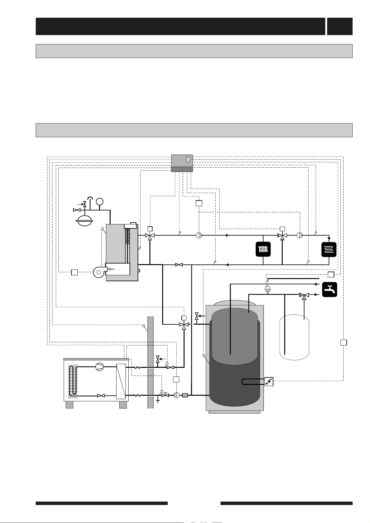
System description
Principle of operation .......................................... 3
System diagram .................................................. 3
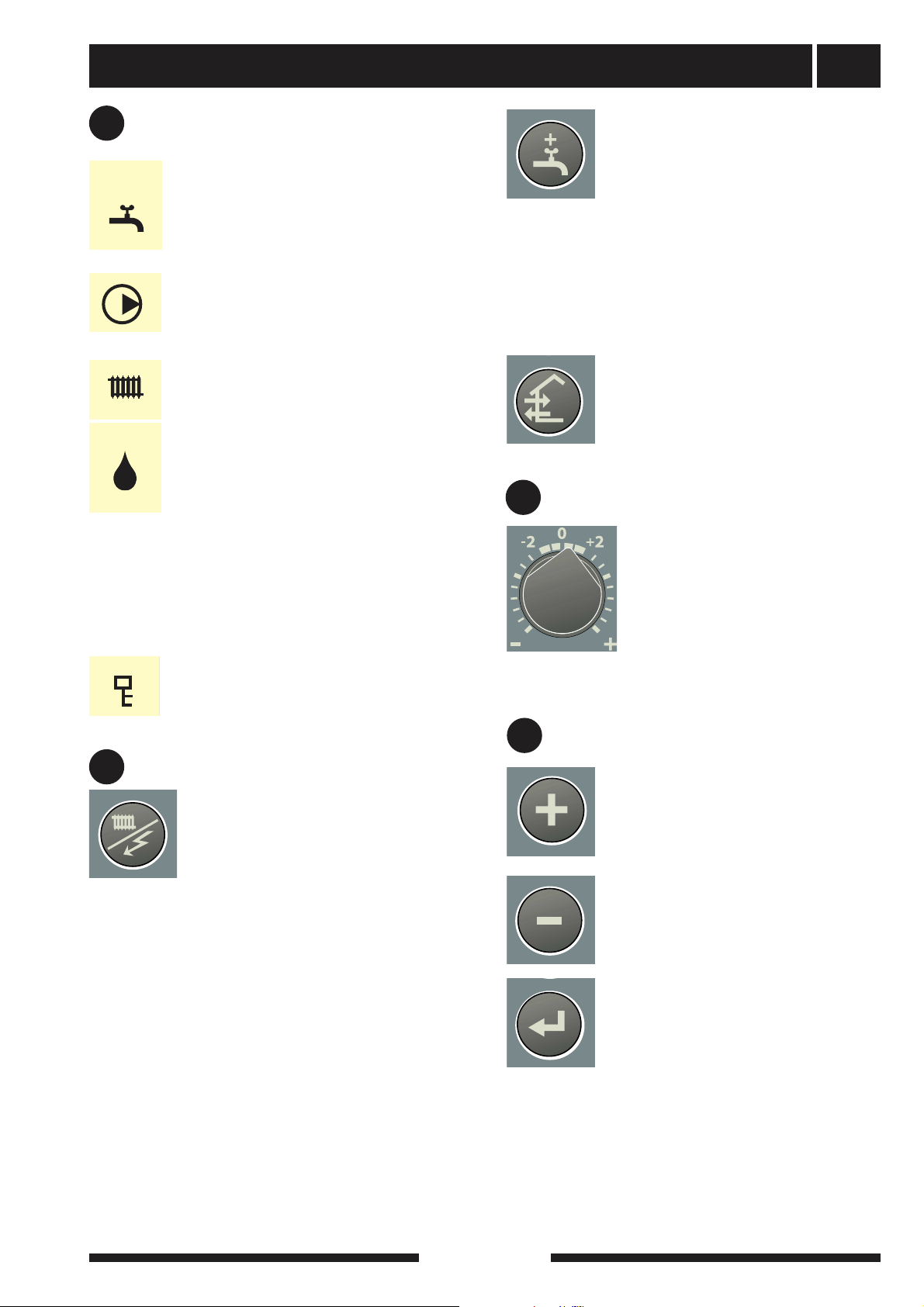
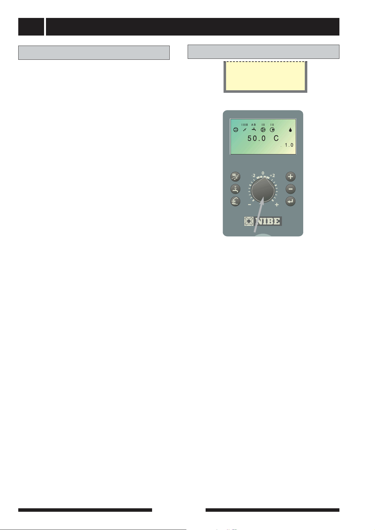
Front panel
Layout .................................................................. 4
Explanation .......................................................... 4
Room temperature
Heating control system ........................................ 6
Default setting ...................................................... 6
Changing the room temperature .......................... 6
Basic values for the automatic heating control system 7
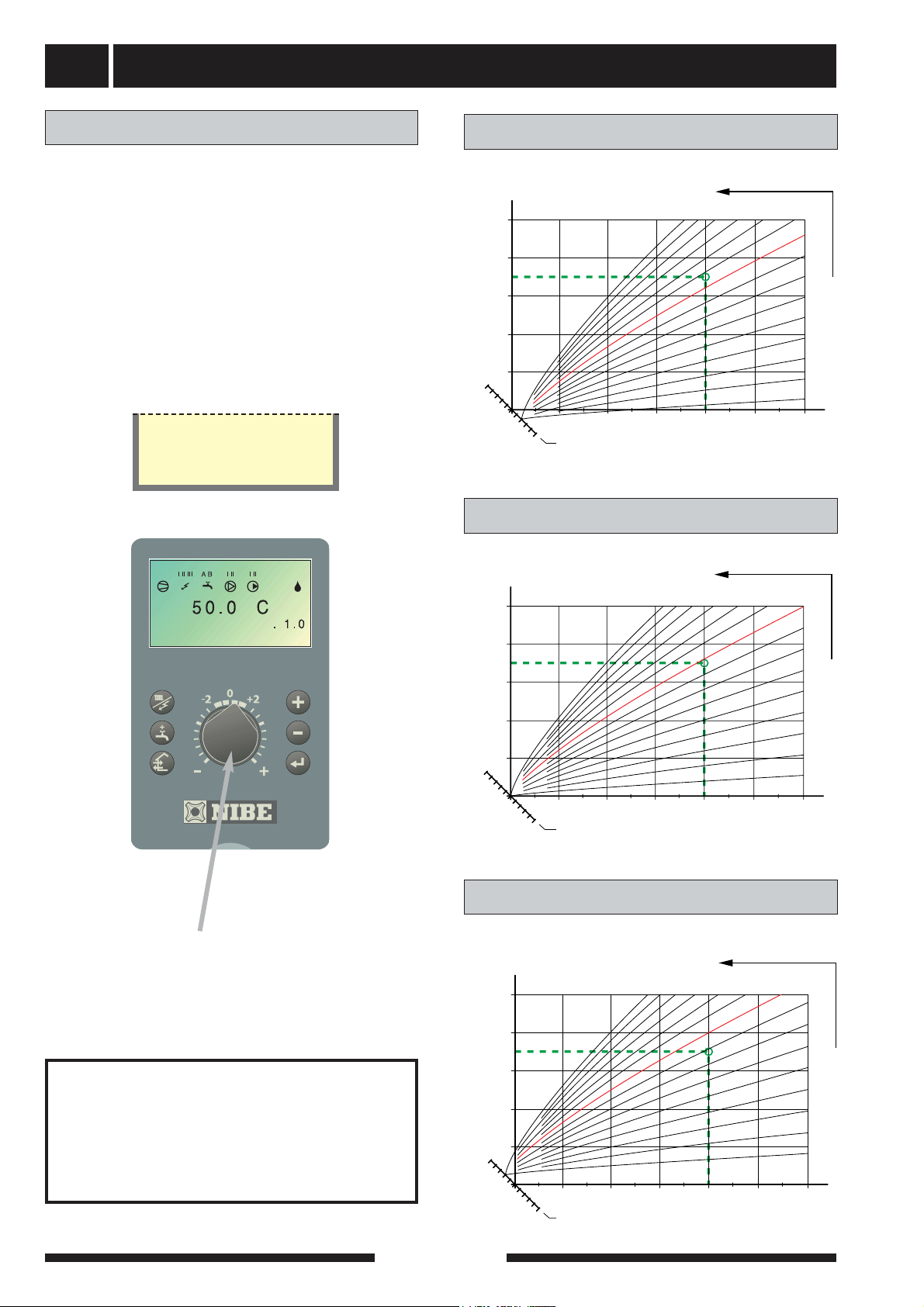
Setting the automatic heating control
system
Offset heating curve -2 .......................................... 8
Offset heating curve 0 ............................................ 8
Offset heating curve +2 .......................................... 8
Setting with diagrams ............................................ 8
Actions with operating disturbances
Low temperature or a lack of hot water .................. 9
High hot water temperature .................................... 9
Low room temperature .......................................... 9
High room temperature .......................................... 9
Switch position “ ” ............................................ 9
Alarm indications on the display .......................... 10
Resetting the miniature circuit breakers .............. 11
General information for the installer
Mounting ............................................................ 12
Inspection of the installation .............................. 12
Electrical connections
Connection .......................................................... 13
Modular cable between SMO 10 and FIGHTER 2010 /
2005
.................................................................. 14
Modular cable/3-conductor between SMO 10 and several
FIGHTER 2010s / 2005s
.................................... 15
Connection of sensors and external units ............ 16
Addition ................................................................ 18
Max. electrical supplement.................................... 18
Max boiler temperature ........................................ 18
Connecting the outside sensor ............................ 18
Centralised load control and load monitor ............ 19
External contacts .................................................. 20
Alarm/alarm outputs ............................................ 20
Docking
General .............................................................. 21
FIGHTER 2010 / 2005 docked to an oil-fired/pellet boiler
21
FIGHTER 2010 / 2005 docked to an immersion heater
after VXV
............................................................ 22
Abbreviations
........................................................ 22
Several FIGHTER 2010s / 2005s docked to an oil-
fired/pellet boiler ..................................................
23
FIGHTER 2010 / 2005 and FIGHTER 310 ............24
FIGHTER 2010 / 2005 docked to immersion heater
after VXV with double jacketed water heater ......24
Commissioning
Settings at start up with FIGHTER 2010 / 2005 .. 25
Settings at start up without FIGHTER 2010 / 2005 .. 25
Commissioning .................................................... 25
Menus to remember ............................................ 25
Control
General ................................................................ 26
Changing parameters .......................................... 26
Key lock ................................................................ 26
Quick movement .................................................. 26
Menu tree ............................................................ 27
Main menus .......................................................... 30
Hot water temperature ........................................ 31
Supply temperature .............................................. 32
Outside temperature ............................................ 33
Heat pump ............................................................ 34
Clock .................................................................... 36
Other settings ...................................................... 37
Service menus
Heat pump settings .............................................. 40
Settings additional heat ........................................ 42
Operating settings ................................................ 43
Quick start ............................................................ 45
Alarm log .............................................................. 45
Component positions
Component locations .......................................... 46
List of components
List of components .............................................. 47
Temperature sensor data .................................... 47
Electrical circuit diagram
Electrical circuit diagram ...................................... 48
Dimensions
Dimensions and setting-out coordinates .............. 52
Accessories
Accessories .......................................................... 53
Enclosed kit
Enclosed kit .......................................................... 54
Technical specifications ...................................... 55

General
SMO 10
2
Installation date
Installer
Type of docking
Accumulator/water heater
Number of FIGHTER 2010s / 2005s
Output size
Shunt group 2
The serial number (103), should always be stated with all
correspondence with NIBE.
089
___________
Chosen output, immersion heater
Circulation pump setting (16), heating medium
Circulation pump setting (40), charge pump
Curve slope setting
Offset heating curve setting
Date__________________ Signed_____________________
Completed when the product is installed.
In order to get the ultimate benefit from your SMO
10 you should read through this Installation and
Maintenance Instruction.
SMO 10 is a control module designed to provide
optimal control of up to nine FIGHTER 2010s /
2005s together with other heating equipment.
Microprocessors ensure that the control module
always works efficiently.
SMO 10 is a Swedish made quality product offering
a long life span and safe operation.

System description 3
SMO 10
Principle of operation
System diagram
The heating medium side and the hot water side must
be fitted with the necessary safety equipment in accor-
dance with the applicable regulations.
NOTE! This is an outline diagram. Actual installations
must be planned according to applicable standards.
The outline diagram is equipped with accessories.
VXV1
PG
SMO 10
HR
HR
HR
HR
HR
P
FIGHTER 2010
FG1 CP1
RG1 RG2
SV1
SV2
CP2 FG2
VVC
VVG
LP1
UG
RG
FG AV
SÄV
TV RV SF
SÄV
SMO 10 is an advanced control module that together
with FIGHTER 2010 / 2005 and existing heating and
hot water equipment forms a complete installation.
SMO 10 can be used for numerous different connec-
tion options, the basic is FIGHTER 2010 / 2005 which
in turn can be docked to an electric boiler, oil-fired boil-
er and accumulator tank, e.g. NIBE VPA.
FIGHTER 2010/2005

Front panel
SMO 10
4
Display
Hotwatertemperature
Left keypad
Offset heating
curve
Display First row:
Compressor symbol
Atogether with a compressor symbol is
shown when step 1 is operational.
Btogether with a compressor symbol is
shown when step 2 is operational.
Only a compressor symbol indicates that the compres-
sor will start, but is blocked as an internal start condi-
tion in FIGHTER 2010 / 2005 has not been met, e.g.
stop temperature.
Supplement symbol
Shown when additional heat is connected.
The line indicates which power step/steps
are currently connected.
Only shown when the immersion heater is
connected.
Power step Iis connected.
Power step II is connected.
Power step III is connected.
Only lightening is shown with hot water
production.
Layout
B
C
Switch
A
D
Right
keypad
A B
E
B
Explanation
I II III
Switch
with three positions 1 - 0 - :
1Normal mode. All control functions connected.
0 The system is completely switched off.
Standby. This position is used in the event
of operating disturbances. Additional heat
output is limited depending on the chosen
connection option. See section Dealing with
malfunctions. NOTE! With outdoor temper-
atures below 0°C there is a risk of freez-
ing.
A

Front panel 5
SMO 10
Hot water symbol.
Indicates when the Extra hot water function
is active.
A is shown when the 24 hour temperature
increase is active
B indicates that a time determined temper-
ature increase, for example periodic, is
activated
Circulation pump symbol.
Shown when the circulation pump is oper-
ational.
Heating system symbols
Shown when house heating is in progress.
Defrosting symbol
Indicates when defrosting of FIGHTER
2010 / 2005 is in progress.
Second row: Value of the current parameter.
Third row: Description of current display para-
meter. Hot water temp is normally
shown.
Fourth row: Shows the current menu number,
key lock and clock
Left keypad
Display
Right keypad
Offset heating curve
D
C
E
Operating mode
This button is used to set the required
operating mode with regard to permit-
ting/blocking the circulation pump and
supplementary energy. The change
does not need to be confirmed with the
Enter button.
The different operating modes are:
Auto mode: SMO 10 automatically selects the oper-
ating mode by taking the outdoor temperature into
account. The circulation pump and additional heat are
permitted to run as needed.
Summer mode: Only production of hot water using
FIGHTER 2010 / 2005. The circulation pump and
additional heat are blocked. However, when Extra hot
water is activated the immersion heater is connected.
Spring/Autumn mode: Only production of heating
and hot water using FIGHTER 2010 / 2005. The circu-
lation pump is operational. The additional heat is
blocked. However, when Extra hot water is activated
the immersion heater is connected.
The current operating mode is shown on the display
when the button is pressed and the mode changes
when you continue to press the button. The display
returns to the normal display mode once the enter but-
ton is pressed. In the event of an alarm from
FIGHTER 2010 / 2005 the different modes are not
shown.
Extra hot water*
The Extra hot water function is activated
using this button. The change does not
need to be confirmed with the Enter but-
ton.
A:
Means that the hot water temperature is increased
to 60 °C (adjustable) during 24 hours. The tempera-
ture then returns to the normal value.
When Acomes on the function is activated.
When Agoes out the function is deactivated.
Plus button
This button is used to scroll through the
menu system (forwards) or increase the
value of the selected parameter.
See the section Control — General.
Minus button
This button is used to scroll through the
menu system (backwards) or lower the
value of the selected parameter.
See the section Control — General.
Enter button
This button is used to select a lower
menu in the menu system, to activate a
parameter change as well as confirm a
parameter change.
See the section Control — General”.
This knob is used to change the
heating curve's parallel offset and in
doing so the room temperature.
Turning clockwise increases the
room temperature. When the knob is
turned menu 2.0 is shown on the dis-
play and the value for the calculated
flow temperature changes.
No function.
A B
B
The key lock can be activated in the main
menus by pressing the Plus and the
Minus buttons simultaneously. The key
symbol will then be shown on the display.
The same procedure is used to deacti-
vate the key lock.
* Works with the immersion heater in hot water
heater.

Room temperature
SMO 10
6
Heating control system
The indoor temperature depends on several factors.
During the hot season, solar radiation and heat given
off by people and equipment are sufficient to keep the
house warm. When it gets colder outside, the heating
system must be started. The colder its gets, the hotter
the radiators must be.
This adjustment is made automatically, however the
basic settings must first be made on the boiler, see the
section Room temperature - Default setting.
The basic heating is set using menu 2.1 and with the
Offset heating curve knob.
If you do not know the correct settings, use the basic
data from the map opposite.
If the required room temperature is not obtained, read-
justment may be necessary.
NOTE! Wait one day between settings so that the tem-
peratures have time to stabilise.
Readjustment of basic settings.
Cold weather conditions
When the room temperature is too low, the heating
curve value is increased in menu 2.1 by one incre-
ment.
When the room temperature is too high, the heating
curve value is decreased in menu 2.1 by one incre-
ment.
Warm weather conditions
If the room temperature is low, increase the offset
heating curve setting by one step.
If the room temperature is high, reduce the heating
curve offset setting by one step.
Basic setting
Offset heating curve
Hotwatertemperature
Menu 2.1 Curve coefficient
9
Curve coefficient
2.1

Room temperature 7
SMO 10
Changing the room temperature manually.
If you want to temporarily or permanently lower or
raise the indoor temperature relative to the previously
set temperature, turn the
Heating curve offset knob
anticlockwise or clockwise. One to three lines approxi-
mately represents a 1 degree change in room tempera-
ture.
NOTE! An increase in the room temperature may be
inhibited by the radiator or floor heating thermostats, if
so these must be turned up.
Changing the room temperature
Offset heating curve
Hotwatertemperature

Setting the heating controls
SMO 10
8
SMO 10 is equipped with an outdoor temperature con-
trolled automatic heating system. This means the flow
temperature is regulated in relation to the current out-
door temperature.
The diagram is based on the dimensioned outdoor
temperature in the area and the dimensioned supply
temperature of the heating system. When these two
values meet, the heating control’s curve slope can be
read. This is set under menu 2.1, Curve Correction.
A suitable value is set using the knob on the front pan-
el, Offset heating curve (38).
A suitable value for floor
heating is -1 and for radiator systems -2.
30
40
50
60
70
°C
FRAMLEDNINGSTEMPERATUR
- 40 °C
UTETEMPERATUR
- 10
0
10 - 20 - 30
15 14 13 12 11 10 9
8
7
6
5
4
3
2
1
VÄRMEKURVA
- 5
+ 5
FÖRSKJUTNING
VÄRMEKURVA (0)
15 14 13 12 11 10
9
8
7
6
5
4
3
2
1
- 40 °C
UTETEMPERATUR
- 10
0
10
- 5
+ 5
30
40
50
60
70
°C
FRAMLEDNINGSTEMPERATUR
- 20 - 30
FÖRSKJUTNING
VÄRMEKURVA (-2)
VÄRMEKURVA
1514 13 12 11 10
8
7
6
5
4
3
2
1
- 40 °C
UTETEMPERATUR
- 10
0
10
- 5
+ 5
30
40
50
60
70
°C
FRAMLEDNINGSTEMPERATUR
- 20 - 30
FÖRSKJUTNING
VÄRMEKURVA ( )
9
VÄRMEKURVA
Offset heating curve 0
Offset heating curve -2
Setting using diagrams
Offset heating curve +2
HEATING CURVE
HEATING CURVE
HEATING CURVE
OFFSET HEATING CURVE
SUPPLY TEMPERATURESUPPLY TEMPERATURE
SUPPLY TEMPERATURE
OUTSIDE TEMPERATURE
OUTSIDE TEMPERATURE
OUTSIDE TEMPERATURE
OFFSET HEATING CURVE
NOTE!
Heating curve in menu 2.1 and Max
supply temp. in menu 2.4 are adjusted
according to the heating system in
question.
Offset heating curve
Hotwatertemperature
Menu 2.1 Curve coefficient
9
Curve coefficient
2.1

Actions with operating disturbances 9
SMO 10
If the operating disturbance cannot be rectified by means of the above an installation
engineer should be called.
If necessary set the Switch to “ ” (manual shunt operation necessary).
In position “ ” the control unit's electronic control is
disconnected, the display screen is not lit.
The automatic heating control system is not opera-
tional, so manual shunt operation is required.
Charge pump (LP1), circulation pump (CP1) additional
heat (TS2) and the immersion heater in the water
heater are operational.
Terminal (11) pos. 3, 19, 21 and 25 are continuously
energized.
Switch position “ ”
■Incorrect values set on the automatic heating con-
trol system.
High room temperature
■Air in boiler or system.
■Large amounts of hot water were used.
■Circuit or main MCB tripped.
■Possible earth circuit-breaker tripped.
■Too low mixer valve setting.
■Switch (8) set to “0”.
■Tripped MCB (7) or fine-wire fuse (33). See the
section Dealing with malfunctions — Resetting the
miniature circuit breakers.
■Tripped temperature limiter. (Contact service)
■Load monitor or external control may have blocked
the electrical output.
■Incorrect values set for hot water production.
Low temperature or a lack of
hot water
■Air in boiler or system.
■Circuit or main MCB tripped.
■Possible earth circuit-breaker tripped.
■MCB tripped (7) or fine-wire fuse (33). See the
section Dealing with malfunctions — Resetting the
miniature circuit breakers.
■Tripped temperature limiter. (Contact service)
■Automatic heating control system settings not correct.
■Day setting set incorrectly so the night change is
active during the day.
■Circulation pump stopped.
■Initial pressure in expansion vessel too low. This is
indicated by low pressure on the pressure gauge,
contact the installer.
■Load monitor or external control may have blocked
the electrical output.
Low room temperature
■Too high mixer valve setting.
■Incorrect values set for hot water production.
High hot water temperature
In the event of malfunction or operating disturbances first check the points
below:
NOTE!
As SMO 10 can be connected to a
large number of external units even
these should be checked.

Actions with operating disturbances
SMO 10
10
NOTE!
The product's serial number should
always be stated with all
correspondence with NIBE.
089
___________
Low Fluid Temp.
This information is shown when the low pressure
switch in FIGHTER 2010 / 2005 has tripped. This may
be because the evaporator is covered in ice or
reduced air flow through the evaporator. The informa-
tion disappears when the pressure switch has been
reset and FIGHTER 2010 / 2005 has been restarted.
The alarm is reset in menu 5.2.
Sensor Alarm
This information is shown when a temperature sensor
in FIGHTER 2010 / 2005 stops working. This may be
due to a broken cable or incorrect installation. The
information disappears when the cause of the fault
has been rectified and FIGHTER 2010 / 2005 restart-
ed. The alarm is reset in menu 5.2.
Alarm indications on the display
Other information can also be shown on the display
besides the standard information. This applies with
malfunctions or for calls to take action. This type of
information is only shown in menu 1.0 (The display
always automatically returns to menu 1.0 approxi-
mately 30 minutes after the last button was pressed).
This information alternates with menu 1.0’s standard
information. At the same time the display’s back-
ground lighting flashes.
The following information can be shown.
LOW FLUID TEMP
1.0
High Pressure
This information is shown when the high pressure
switch in FIGHTER 2010 / 2005 has tripped. This may
be due to a too low charge flow. The information dis-
appears when the pressure switch has been reset and
FIGHTER 2010 / 2005 has been restarted. The alarm
is reset in menu 5.2.
HIGH PRESSURE
1.0
Motor Security
This information is shown when the motor cut-out on
FIGHTER 2010 / 2005 has tripped. This may be due
to a phase failure because of a tripped fuse or incor-
rect motor protection setting. The information disap-
pears when the fault has been rectified and FIGHTER
2010 / 2005 has been restarted. The alarm is reset in
menu 5.2.
MOTOR SECURITY
1.0
SENSOR ALARM
1.0
F2010 Communic.
Fault text shown when contact between SMO 10 and
FIGHTER 2010 / 2005 has been lost. This may be due
to a broken cable or that the voltage to FIGHTER
2010 / 2005 is not switched on. The information
disappears when SMO 10 and FIGHTER 2010 / 2005
are restarted.
NOTE! SMO 10 should be switched on within 5 min-
utes of FIGHTER 2010 / 2005 being restarted and
communication between the products is restored. The
alarm is reset in menu 5.2.
F2010 COMMUNIC.
1.0
Temp. Limit
Shown when a temperature limiter may have tripped.
The information disappears once the fault has been
rectified and the alarm reset on menu 9.3.6.
TEMP. LIMIT
1.0

Actions with operating disturbances 11
SMO 10
Alarm indications on the display
Supply sensor
This information is shown when a fault on the flow
temperature sensor has been registered. The alarm
may be due to a faulty sensors or broken sensor
cable. The information disappears once the fault has
been rectified and the alarm reset on menu 9.3.6.
Warmwater Alarm
This information is shown when a fault on the hot
water temperature sensor has been registered. The
alarm may be due to a faulty sensors or broken sensor
cable. The information disappears once the fault has
been rectified and the alarm reset on menu 9.3.6.
WARMWATER ALARM
1.0
SUPPLY SENSOR
1.0
Warmwater el.power
This information is shown when a fault on the immer-
sion heater temperature sensor has been registered.
The alarm may be due to a faulty sensors or broken
sensor cable. The information disappears once the
fault has been rectified and the alarm reset on menu
9.3.6.
WARMWATER EL.POWER
1.0
Miniature circuit breakers (7) are located on the under-
side of SMO 10. Normal mode on the miniature circuit
breakers is “1” (to the right).
Resetting the miniature circuit breakers

General information for the installer
SMO 10
12
Current regulations require the heating installation to
be inspected before it is commissioned. The inspec-
tion must be carried out by a suitably qualified person
and should be documented. The above applies to
installations with a closed expansion vessel. If the
electric boiler or the expansion vessel is replaced, the
installation must be inspected again.
Inspection of the installation
SMO 10 is installed by mounting it on a wall using four
screws. There are two holes at the rear for mounting
and two straight-through holes in the electrical con-
nection area.
Mounting
405
406
328
276

Electrical connection 13
SMO 10
SMO 10 must be installed via an isolator switch with a
minimum breaking gap of 3 mm.
Disconnect the control module before insulation test-
ing the house wiring.
Connection
NOTE!
Electrical installation and service must
be carried out under the supervision of
a qualified electrician. Electrical
installation and wiring must be carried
out in accordance with the stipulations
in force.
NOTE!
In order to prevent operating
disturbances, sensor cables and
modular cables should be kept separate
from the power cables when cable
routing.
NOTE!
Work behind screwed covers may only
be carried out under the supervision
of a qualified installation engineer.
LEK
Terminal block (11)
Terminal block (14)
Load monitor card (2)
Terminal block (4), communi-
cation FIGHTER 2010 / 2005

Electrical connection
SMO 10
14
For communications between SMO 10 and FIGHTER
2010 / 2005 use the supplied modular cable of 15 m.
The modular cable is connected between SMO 10
position (4) and FIGHTER 2010 / 2005 position (44),
see the Installation and Maintenance Instruction.
Routing of the modular cable in FIGHTER 2010 / 2005
should be done from below in the cable glands on left-
hand side of the heat pump, seen from the front.
LEK
44
FIGHTER 2010 / 2005 SMO 10
Modular cable between SMO 10 and one FIGHTER 2010 / 2005
4
LEK
29
4
SMO 10
FIGHTER 2010
44
FIGHTER 2010/2005
NOTE!
The modular cables should be routed
separately from power cables when
cable routing.

Electrical connection 15
SMO 10
VP1: The modular cable is connected between SMO
10 position (4) and FIGHTER 2010 / 2005 VP1
position (44).
VP2: The screened 3-conductor cable is connected
between FIGHTER 2010 / 2005 VP1 position
(44) and FIGHTER 2010 / 2005 VP2 position (44).
VP3: The modular cable is connected between
FIGHTER 2010 / 2005 VP2 position (44) and
FIGHTER 2010 / 2005 VP3 position (44).
Routing of the cable in FIGHTER 2010 / 2005 should
be done from below in the cable glands on left-hand
side of the heat pump, seen from the front.
LEK
44
FIGHTER 2010 / 2005
Modular cable/3-wire between SMO 10 and several
FIGHTER 2010s / 2005s
29
4
SMO 10
FIGHTER 2010 VP1
FIGHTER 2010 VP2
FIGHTER 2010 VP3
44
44
44
SMO 10
4
LEK
FIGHTER 2010 / 2005 VP3 FIGHTER 2010 / 2005 VP2 FIGHTER 2010 / 2005 VP1 SMO 10
NOTE!
The modular cables should be kept
separate from power cables when cable
routing.

Electrical connection
SMO 10
16
Connection of sensors and external units
7
230 V/12 V
11
F1
F3
Re1 Re3 Re2 Re7
Re4 Re5
Re8 Re10
Re9
Re6 Re11 Re12 Re13 Re14
LNLaddpump
F 2010 VXV 1 Shunt1
L1 N
CP1/CP2 TS2 TS1 TS3 N VV VVC Shunt2
NNNNNN
Opto Opto
Opto Opto
SMO 10
Externt
N
L1 L1
Pool
styrning
Pool L1
VXV 2
Pool
– VV S Ö N
230V
L1 N
L1 L1 SNÖ N
L1 N
L1
–
Tillsats Elpatron
Varmvatten
*
*
*
*
F2010
/ 2005
External
Charge
pump
Pool
control Pool
Addition Immersion heater
Hot water

Electrical connection 17
SMO 10
Connection of sensors and external units
11
SMO 10
Externt
Pool G UG
57 58 59 60
Fas1 Fas3
Fas2
* The suppressor supplied in the enclosed kit should
be fitted either to terminal 11 or on the connector.
NOTE!
In order to prevent operating
disturbances, sensor cables and
modular cables should be kept separate
from the power cables when cable
routing.
External

7 F TS1 + TS2 + TS3
Electrical connection
SMO 10
18
Connecting the outside sensor
Supplement
The outside sensor (UG) must be installed in a shad-
ed location on a wall facing north or north-west, where
it will not be affected by any morning sun. The sensor
is connected with two-wire cable to positions “55” and
“56” on terminal (11), see section “Electrical connec-
tions - Connection of sensors and external units”.
If a conduit is used it must be sealed to prevent con-
densation in the sensor capsule. The minimum cable
cross section should be 0.4 mm2up to lengths of 50
metres, for example, EKKX or LiYY.
Max. electrical addition (binary)
The setting of the different maximum immersion
heater outputs is done using the knob (101) on the
load monitor card (2).
The setting of the different maximum boiler/hot water
heater temperatures is done using the knob (102) on
the load monitor card (2).
Max boiler temperature/hot
water heater
65 C
75 E
55 A
Boiler temperature Knob position
60 B
70 D
80 F
2102 101
The additional heat should be equipped with its own
safety equipment according to applicable regulations.
Safety equipment can comprise of a temperature lim-
iter, isolator switch and a possible by-pass.
SMO 10 gives 230 V control voltage for load regula-
tion.
3 B TS1+TS2
5 D TS1 + TS3
1 – TS1
No. of steps Knob position Addition
2 A TS2
4 C TS3
6 E TS2 + TS3
Max. electrical addition (linear)
3 B TS1+TS2+TS3
1 – TS1
No. of steps Knob position Addition
2 A TS1+TS2
Other manuals for SMO 10
2
Table of contents
Other Nibe Control System manuals
Popular Control System manuals by other brands

Revo
Revo TX341 operating instructions

Wondrwall
Wondrwall Light switch user manual

Leb Electronics
Leb Electronics CTR640 instructions

Norac
Norac UC4 Plus Rogator 64 Series installation manual

Distech Controls
Distech Controls EC-BOS-6AX Mounting and wiring instructions

Verasys
Verasys LC-SBH200-0 Product bulletin