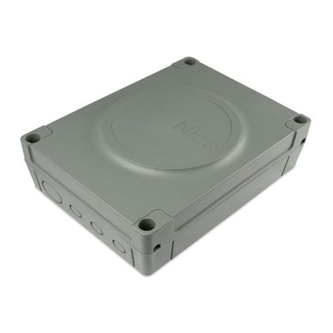
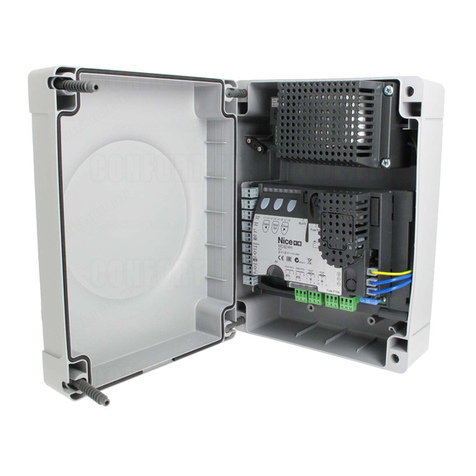
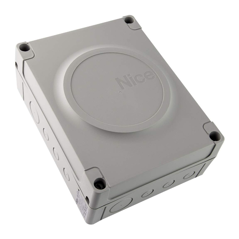
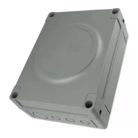
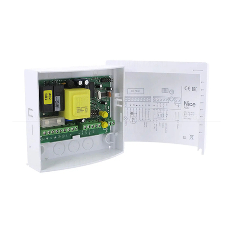
Nice Mindy A500 Product manual

control unit
Mindy A500
Instructions and warnings for the fitter
Istruzioni ed avvertenze per l’installatore
Instructions et recommandations pour l’installateur
Anweisungen und Hinweise für den Installateur
Instrucciones y advertencias para el instalador
Instrukcje i uwagi dla instalatora
Aanwijzingen en aanbevelingen voor de installateur

2
6Operating modes
7Programming
7.1 Programmable functions
7.2 Description of functions
8Using 2 central units on opposite wings
9Accessories
10 Maintenance
10.1 Environmental protection measures
10.2 Technical specifications
Mindy A500
Introduction:
This manual has been especially written for use by technical personnel
qualified to carry out installation. No information given in this manual can
be considered as being of interest to end users! This manual is enclosed
with control unit A500 and may not be used for different products!
Important notice:
The A500 control unit has been designed to control an electromechani-
cal actuator for automating gates or doors. Any other use is considered
improper and is consequently forbidden by current laws.
May we remind you that the automation system you are about to
install is classified as “building a machine” and therefore enters the field
of application of European directive 89/392 EEC (machine directive).
This directive includes the following prescriptions:
-Only trained and qualified personnel should install the equipment
-The installer must first perform the “risk analysis” of the machine
-The equipment must be correctly and professionally installed in compli-
ance with all relevant standards.
-After installation, the machine owner must be issued with the “declara-
tion of conformity”.
This product may only be installed and serviced by qualified personnel,
therefore, in compliance with current laws, standards or directives.
When designing and producing its products, Nice observes all applica-
ble standards (please see the attached declaration of conformity) but it
is of paramount importance that installers continue to strictly observe the
same standards when installing the system.
Unqualified personnel or those who are unaware of the standards
applicable to the “automatic gates and doors” category may not install
systems under any circumstances
Whoever ignores such standards will be held responsible for any
damage caused by the system!
Do not install the unit before you have read all the instructions thor-
oughly!
Particular warnings concerning the suitable use of this product in relation
to the 73/23/EEC “Low Voltage” Directive and subsequent modification
93/68/EEC:
- This product responds to the provisions foreseen by the “Low Voltage”
Directive if used in the configurations foreseen in this instructions manu-
al and in combination with the articles present in the Nice S.p.a. product
catalogue. If the product is not used in configurations or is used with oth-
er products that have not been foreseen, the requirements may not be
guaranteed; the use of the product is prohibited in these situation until
the correspondence with the requirements foreseen by the directive
have been verified by installers.
Particular warnings concerning the suitable use of this product in relation
to the 89/336/EEC “Electromagnetic Compatibility” Directive and subse-
quent modifications 92/31/EEC and 93/68/EEC:
- This product has been subjected to tests regarding the electromag-
netic compatibility in the most critical of use conditions, in the configu-
rations foreseen in this instructions manual and in combination with arti-
cles present in the Nice S.p.A. product catalogue. The electromagnetic
compatibility may not be guaranteed if used in configurations or with
other products that have not been foreseen the use of the product is
prohibited in these situations until the correspondence to the require-
ments foreseen by the directive have been verified by those performing
the installation.
!
!
!
Index:
1Description of the product
2Installation instructions
2.1 Input voltage selection
2.2 Wiring diagram
2.3 Description of connections
2.4 Notes about connections
3Testing
4Adjustments
5Obstacle adjustment system

GB
3
R
Q
S
POMN
AP CH
L
H
I
G
F
T
A
U
BC
D
E
TLM
F2= 0.5 A
"PIU" OK
1
TPTL F
F1= 0.5 A
COM
RADIO
400
230
AMains power switch 230 / 400 V
BOverload cut-out
CPower supply transformer
DControl unit power fuse (500mA)
EAdjustment trimmer
FRadio terminal board
GFunction selection dip-switch
HOK LED
IConnector for Door controls
LInput status LED’s
MInput/output control terminal board
NLimit switch input terminal board
OPhototest output terminal board
PMotor power output
QFlashing light output
RFlashing light fuse (500mA)
SMotor manoeuvre remote control switches
TFlashing light activation relay
UBrake activation relay
1) Description of the product:
This unit controls an alternate current three-phase or single-phase
motor at 230V or 400V for automatic doors and gates. It features
obstacle detectors (anti-crush devices) and a braking system which
reduces inertia during the stopping phase. It also features a series of
functions that can be selected by dip-switches (mini-switches) and
adjustments performed by trimmers.
The control unit features input status LED’s located near such inputs,
while another LED near the microprocessor indicates that the internal
logic works correctly.
2) Installation:
Before starting to install the unit, check the sturdiness and
mechanical consistency of the gate and make sure safety stops and
minimum distances are respected. Carry out a careful and thorough
“risk analysis” of the automatic system, evaluate the safety devices to
be installed with particular care and always fit an emergency stop
device.
Make absolutely sure that the mechanical stops are of the right shape
and strong enough to stop the motor in all conditions; they must be
able to absorb all the kinetic energy accumulated during movement
without deforming in the slightest.
Do not install the motor without the “Mechanical travel
stops”
Besides the standards referring to electrical installations in general,
automatic machines, doors and gates, we also supply some specific
notes that will make the whole system even safer and more reliable:
-The power line leading to the unit must always be protected by a
circuit breaker or three 5A-fuses; a differential switch is
recommended but not essential if there is already one up-line from
the system.
-Power the unit using a 5 x 1.5 mm2cable (3 phases + neutral +
earth); should the distance between the unit and the earth
connection exceed 30 m, install an earth plate near the unit.
-Use wires with a minimum cross section of 0.25 mm2to connect low
voltage safety circuits.
Use shielded wire if the length exceeds 30 m and connect the earth
braid only on the unit side.
-Only use cables (various individually insulated wires plus an
additional general insulation); never use single wires even if they are
protected inside ducts.
-It is absolutely forbidden to connect cables in buried boxes even if
they are completely watertight.
Make sure you have all the necessary materials suitable for this use.
The unit must be installed correctly in order to guarantee an adequate
level of safety and protection against atmospheric agents. Please
bear in mind that the unit contains particularly delicate live parts and
electronic components.
The unit is supplied in a container which, if appropriately installed, will
guarantee a protection level of IP55 (in compliance with CEI 70-1 and
IEC 529) which means it is also suitable for outdoor installation.
However, several simple but important rules must be followed:
-Install the unit on a permanent surface, perfectly flat and adequately
protected against knocks, making sure that the unit bottom is at least
40 cm from the ground.
-Install cable or pipe leads only at the bottom of the unit; for no
reason whatsoever must the side and top walls be perforated. The
cables must only enter the unit from the bottom!
!
1

4
44 AERIAL
19 P.P.
M
PHOTO
Max 200 mA
24 Vac
SCA
COM (24V)
24 Vac Max 200mA
FCC
COM
FCA
PHOTOTEST
LAMP.
230 Vac 40W
400 V
U
W
V
1
2
4
3
5
6
7
ALT
12
9
8
11
10
15
13
14
18
17
16
"PIU" OK
CH
AP
20
21
41
43
42 2°Ch RADIO
3
400
COM
RTS
400 V
F2= 0,5 A
TLM
TPTL F
+
-
+
-
+
-
2.2) Wiring diagram:
Under no circumstances, while wiring or plugging in the various
cards, may the unit be electrically powered, to safeguard the
operator and avoid damaging the components.
Please also bear in mind that if the inputs of the NC (Normally Closed)
contacts are not used they should be jumpered with the “common”
terminal; if there is more than one contact, then they should be
connected in SERIES. If the inputs of the NO (Normally Open)
contacts are not used they should be left free and if there is more
than one contact then they should be connected in PARALLEL. The
contacts must be of the mechanical type and potential-free; no
connections are allowed, such as those defined as "PNP", "NPN",
"Open Collector" etc..
Before making connections, check that the selection corresponds to
the available input voltage.
Any errors during the selection can seriously damage the
components of the control unit!
The drawing in figure shows the connections of the control unit with
three-phase 400V power supply.
To connect the control unit with 230 Volt single-phase or three-phase
power inputs, please refer to the drawings in figure 3a-3b.
N.B.:
Only qualified and expert personnel may carry out installation and subsequent maintenance operations following the rules of good workmanship and
in compliance with EEC directive 89/392 (Machine Directive) and, in particular, EN 60204 (Electrical wiring of machines).
2.1) Input voltage selection:
The power unit can either work with three-phase or single-phase power supply (see wiring diagrams) with voltages of
400V or 230V. Select the input voltage by fitting in a jumper between the “COM” terminal and the “230” terminal or the
“400” terminal as shown in figure.
2
COM
230
400

GB
5
230
COM
230 V Single-phase
LN
230 V
AP
COM
3
1
2
F2= 0.5 A
CH
6
4
5
7
M
230 Vac 40W
400
COM
RTS
230 V Three-phase
230 V
V
U
3
2
1
F2= 0.5 A
W
6
5
4
7
M
230 Vac 40W
400
COM
400 V Three-phase
RST
400 V
V
U
1
2
3
W
6
4
5
7
F2= 0.5 A
M
230 Vac 40W
2.3) Descriptions of connections:
All the connections are made by means of special terminals located
on the lower side of the electronic card. Only the power input line
should enter the upper part, directly connected to the overload cut-
out terminals.
To connect the earth circuit to the control unit and motor, use
terminals 6-7 wherever possible.
If the control unit is powered by a single-phase system just two wires
must be connected to the first two terminals to the left of the overload
cut-out (the third terminal being unused). Connect the single-phase
motor and relative condenser as shown in figure 3a.
Take care when selecting 400V or 230V input voltage.
A brief description of the possible connections of the control unit outputs follows.
1-2 : Flashing light = Connection to 220 Vac max. 40W flashing light
3-4-5 : Motor = Line to motor 230Vac / 400Vac
6-7 : Earth = Control unit and motor earth connection
8-9 : Phototest = 24 Vac output to power photoelectric cell transmitters (Max. 200mA)
10 : Open limit switch = OPEN limit switch input
11 : Common = Common for limit switch inputs
12 : Close limit switch = CLOSE limit switch input
13-14 : 24 Vac = 24 Vac output to accessories Max. 200mA (400mA if phototest is not used)
15 : Common = Common for all inputs
16 : Gate open indicator = Max. 24 Vac output for gate open indicator 2W
17 : Stop = Input with STOP function (Emergency, shutdown or extreme safety)
18 : Photocell = Input for safety devices (photoelectric cells, pneumatic edges)
19 : Step-by-step = Input for cyclic functioning (OPEN STOP CLOSE STOP)
20 : Open = Input for opening
21 : Close = Input for closing
41-42 : 2° Radio Ch = Output for the second radio receiver channel, if any
43-44 : Aerial = Input for the radio receiver aerial
There are two additional slots on the unit card for optional cards:
RADIO =Slot for NICE radio receivers
PIU =Slot for “PIU” expansion card with extra functions
We recommend waiting until installation is complete before plugging in the optional RADIO or PIU cards.
The optional cards are not essential for system operation and, if used, they make troubleshooting more complicated.
Connecting the control unit with 230V single-phase power supply
Connecting the control unit with 230V three-phase power supply
Connecting the control unit with 400V three-phase power supply
3b
3c
3a

6
2.4) Notes about connections:
Most connections are simple; many of them are direct connections to
a single user point or contact but others are a little more complicated.
A particular description should be made of the “Phototest” output;
this is the best possible solution in terms of reliability as regards safety
devices and puts the control unit and safety photocells in “category 2”
according to UNI EN 954-1 standard (ed. 12/1998).
Before every manoeuvre is begun, the relative safety devices are
checked and only if everything is in order will the manoeuvre start.
Should the test be unsuccessful (photocells blinded by the sun, short
circuited cables, etc.) the failure is identified and the manoeuvre is not
carried out.
This can only be achieved by using a certain configuration in the safety
device connections that require the photocell transmitter power input
to be connected to terminals 8-9 while the receiver power input should
be derived from the accessories output (terminals 13-14).
When movement is required, it is first checked that all the receivers
involved in the movement give their consent, then the phototest output
is turned off after which it is checked that all the receivers signal the fact
by removing their consent; the phototest output is finally reactivated
and the consent of all the receivers is verified once more.
Synchronism should always be activated on the two transmitters by
cutting the jumpers; this is the only way of ensuring that the two pairs
of photoelectric cells do not interfere with one another.
Check the instructions in the photocell manual regarding
synchronised functioning.
If a PHOTO input is not used (e.g.: PHOTO2) and the phototest
function is required, jumper the unused input with phototest output
terminal n°9.
TX
PHOTO 2
(PIU card)
8
TX
PHOTO
9
RX
RX
14
13
15
PIU (10)
18
Once the motor and various accessories have been connected you
can now check all the connections and test the installation.
ATTENTION: the following operations entail working on live
circuits; most of these run on extra-low safety voltage so they
are not dangerous but some are powered by mains voltage
which means they are HIGHLY DANGEROUS! Pay the greatest
of attention to what you are doing and NEVER WORK ALONE!
Work on the control unit should be started in the “manual mode” and
with all the functions deactivated (dip-switches OFF); in all cases,
when working in the manual mode and the control key is released,
the motor will stop immediately. Also check that all the adjustment
trimmers are at a minimum (turned fully anti-clockwise); only the
“FORCE” trimmer can be positioned on maximum.
A) Unlock the gate and take it halfway the run and then lock it;
now it is free to move in either the opening or closing direction.
B) Make sure you have selected the correct input voltage on the
terminal board to the left of the overload cut-out.
C) Power the unit and check that voltage between terminals 13-
14 and 8-9 is 24 Vac.
As soon as the unit is powered the indicator lights (LED’s) on the
active inputs should turn on and shortly after the "OK" LED should
start flashing regularly. If none of these events occur, turn power off
immediately and check the connections more carefully.
The “OK” LED in the centre of the card has the job of signalling the
state of the internal logic: regular flashing at 1 second intervals means
that the internal microprocessor is active and waiting for commands.
When the microprocessor recognises a variation in the state of an
input (whether it is a command or function dip-switch input) it
generates a rapid double flash even if the variation does not have any
immediate effect. Extremely rapid flashing for 3 seconds means that
the control unit has just been powered or is performing internal
testing, lastly, irregular flashing means that the test has been
unsuccessful and that a fault has occurred.
D) Now check that the NC-contact inputs LED’s are on (all safety
devices active) and that the NO-contact inputs LED’s are off
(no command present); if this is not the case, check the
connections of the various devices and make sure they are in
good working order.
E) Check that all the safety devices of the unit are in proper
working order (emergency stop, photocells, pneumatic edges,
etc.); each time they cut in, the relative STOP or PHOTO LED
should turn off.
F) Check the limit switches are connected properly; move the
gate and check that once the required point is reached the
relative limit switch cuts in and switches off the relative LED on
the control unit.
G) Now make sure that movement is in the right direction, that is,
check that the movement set on the unit corresponds to that
of the wings. This check is of paramount importance. If the
direction is wrong, in some cases (in the semiautomatic mode,
for instance) the gate might appear to be working properly. In
fact, the OPEN cycle is similar to the CLOSE cycle but with one
basic difference. The safety devices are ignored in the closing
manoeuvre, which is normally the most dangerous, and they
will trigger in the opening manoeuvre causing the gate to close
up against the obstacle with disastrous results!
To see whether the direction of rotation is correct, give a short
pulse to the Step-by-Step input; the first manoeuvre the unit
will carry out after being powered is always an OPEN one, so
simply verify that the gate starts opening; if this movement is
incorrect, proceed as follows:
1 – Turn the power off
3) Testing:
!
4

GB
7
2 – For the three-phase motor, exchange 2 of the 3 motor
connections. For the single-phase motor, exchange the
“OPEN” and “CLOSE” motor connections.
Once this has been done, check if the direction of rotation is now
correct by repeating the procedure described in point “G”.
H) Perform a complete movement of the actuator; we
recommend to always work in the manual mode with all
functions deactivated. Use the command inputs to move the
gate until it reaches the open point; if everything works
normally, continue with the closing manoeuvre and move the
gate until it reaches the stop point.
I) Carry out several open and close manoeuvres in order to
evaluate any defects in the mechanical structure of the
automation system and pinpoint any specific points of friction.
L) Test the PHOTOCELL safety devices triggering; they have no
effect in the opening manoeuvre but they will stop movement
during the closing manoeuvre. If the PIU card is plugged in,
test the PHOTOCELL 2 input: it has no effect in the closing
manoeuvre but it will stop movement during the opening
manoeuvre. The devices connected to the STOP input work
during both the opening and closing manoeuvres and stop
movement in each case.
The control unit can be adjusted in 3 ways by means of adjustment
trimmers to act on the following parameters:
Working time (TL):
Adjusts the maximum duration of the opening or closing manoeuvre.
Pause time (TP):
In the “automatic” mode, this adjusts the delay between the end of
the opening manoeuvre and the beginning of the closing manoeuvre.
Force (F):
Adjusts the trigger threshold of the overload protection.
To adjust the working time TL, select the “Semiautomatic” operating
mode by moving dip-switch N°1 to ON and adjust the TL trimmer to
halfway along the travel distance. Then run a complete opening cycle
followed by a complete closing cycle and readjust the TL trimmer in
order to leave enough time for the whole manoeuvre plus a margin of
about 2 to 3 seconds.
If the trimmer is at maximum and there still is not enough time, cut
the TLM jumper on the printed circuit between the TL and the TP
trimmers in order to provide more working time.
To adjust the pause time TP, select the “Automatic” operating mode
by moving dip-switch N°2 to ON and adjust the TP trimmer as
required. Then carry out an opening manoeuvre and check the time
taken for the gate to close automatically.
Take great care when adjusting the FORCE (F) trimmer as this may
affect the level of safety of the automatic system. Trial by error is
required to adjust this parameter, measuring the force required to
allow the system to work. Please follow the instructions shown in the
next chapter.
Adjustment is not linear in the whole range of the trimmer but is
concentrated in one area; adjustment may have no effect in the first
part of the trimmer while further on a considerable variation may be
obtained by turning it slightly. The reason for this lack of linearity is
due to the need to ensure the trimmer works with a wide range of
single-phase and three-phase motors.
4) Adjustments:
5) Obstacle detection system:
This control unit is fitted with an obstacle detection system based on
methods for controlling motor stress depending on the level of
absorbed power. This technique is commonly known as “overload
cut-out” and inverts or stops the manoeuvre depending on the
programmed operating mode.
In the control unit, the control system can work in two ways, “normal”
or “intelligent”; these are selected by dip-switch N° 8 (please see
chapter on “Programmable functions”).
In the “normal” mode, the function is activated when the power
absorbed by the motor reaches the threshold value set up with the
force trimmer. This level is fixed and has the disadvantage that any
increases in absorbed power due to variations in voltage,
temperature, etc., can give rise to apparently unjustified manoeuvres.
The “intelligent” mode was developed to overcome this limit. This
function adjusts the cut-in threshold set up with the trimmer by
means of an intelligent feature which is able to tell the difference
between slow variations caused by the above reasons and rapid
variations caused by an obstacle.
N.B.: In both systems, the overload cut-out triggering due to
obstacle detection is inactive during the initial movement phase and
for a duration of 1.5 seconds.
Force and other adjustments must comply with recent European
standards, prEN 12453: safety when using powered doors –
requirements and classifications; and prEN 12445: safety when using
powered doors – test methods. These standards require
measurements to be used in order to limit the forces in the movement
of automatic doors.
5
TLM
TPTL F
+
-
+
-
+
-

8
6) Operating modes:
In the manual operating mode, the OPEN input enables the opening
manoeuvre and the CLOSE input enables the closing manoeuvre.
The STEP-BY-STEP input enables an alternating closing and opening
manoeuvre.
Movement stops as soon as the command in input stops. If the limit
switches trigger, or PHOTOCELL 2 (on the PIU card) fails to enable
movement during an opening manoeuvre, movement will stop;
during a closing manoeuvre, on the other hand, movement will also
stop if PHOTOCELL does not enable movement. Both in the opening
or closing phases, movement will be brought to an abrupt halt by
means of STOP. When a movement is stopped, stop the command
in input before a new command is given that starts a new movement.
When one of the automatic functioning modes (semiautomatic,
automatic or always closes) is operational, a command impulse on
the OPEN input will begin an opening manoeuvre. An impulse to the
STEP-BY-STEP input begins an alternating closing and opening
manoeuvre. A second impulse on the STEP-BY-STEP input or on the
same input that started movement will cause it to stop.
Both in the opening or closing phases, movement will be brought to
an abrupt halt by means of STOP.
If, a command input is given a continuous signal instead of an
impulse, a state of “priority” will be created in which the other
command inputs are disabled (this is useful if you want to connect a
timer or a Night-Day selector).
If an automatic functioning mode has been chosen, the opening
manoeuvre will be followed by a pause and then by a closing
manoeuvre. If PHOTOCELL triggers during the pause, the timer will
be reset with a new pause time; if, on the other hand, there is a STOP
during the pause, the closing function will be cancelled and the
system will STOP.
Nothing will happen if PHOTOCELL triggers during an opening
manoeuvre but if PHOTOCELL 2 (on the PIU card) triggers, this will
invert the direction of movement; if PHOTOCELL triggers during a
closing manoeuvre, this will invert the direction of movement followed
by a pause and then by a closing manoeuvre.
The unit features a set of microswitches used to operate various
functions so as to make the system more suitable to user needs and
safer in various conditions of use. All the functions can be activated
by moving the relative dip-switch to the “On” position and
deactivated by moving them to “Off”.
ATTENTION: some of the programmable functions are connected
with safety aspects; carefully evaluate the effects of a function and
see which function gives the highest possible level of safety.
When servicing a system, before modifying a programmable function,
find out why certain decisions were made during installation and then
make sure the level of safety will not be impaired by the modified
programme.
7) Programming:
7.1) Programmable functions:
Use the FUNCTIONS dip-switch to select the various functioning modes and add the functions required according to this table:
Switches 1-2: Off-Off = “Manual” movement (Man Present)
On -Off = “Semiautomatic” movement
Off-On = “Automatic” movement (Automatic Closing)
On -On = “Automatic + always closes” movement
Switch 3: On = Condominium operating mode <Not available in the Manual mode>
Switch 4: On = Pre-flashing
Switch 5: On = Close again 5” after Photocell <only in the automatic mode>
Switch 6: On = “Photocell” also in opening
Switch 7: On = Phototest
Switch 8: On = Intelligent overload cut-out
Switch 9: On = Partial inversion following overload cut-out <disabled in the manual mode>
Switch 10: On = Brake
If a dip-switch is “Off” the function will not be activated, if it is “On” the function will be activated.
Some functions are only possible in specific conditions indicated in the notes between the symbols “<...>”.
1
on
off
6

GB
9
7.2) Description of functions:
Here is a brief description of the functions that can be added by moving the relative dip-switch to “ON”.
Switches 1-2: Off-Off = “Manual” movement (man present)
On -Off = “Semiautomatic” movement
Off-On = “Automatic” movement (automatic closing)
On -On = “Automatic + Always Closes” movement
In the “Manual” functioning mode, the gate will only move as long as the relative control key is held down.
In the “Semiautomatic” functioning mode a command impulse will perform the whole movement until the Working Time limit expires or the
mechanical stop is reached. In the “Automatic” functioning mode, an opening manoeuvre is followed by a pause and then an automatic closing
manoeuvre.
The “Always Closes” function cuts in following a power failure; if the gate is open, a closing manoeuvre takes place, automatically preceded
by 5 seconds’ pre-flashing.
Switch 3: On = Condominium functioning mode (not available in the Manual mode)
In the Condominium functioning mode, once an opening manoeuvre has started, it cannot be interrupted by other command pulses on STEP-
BY-STEP or OPEN until the gate has finished opening.
During a closing manoeuvre, a new command pulse will stop the gate and reverse the direction of movement in order to open the gate.
Switch 4: On = Pre-flashing
A command impulse activates the flashing lamp followed by movement 5 seconds later (2 seconds later in the manual mode).
Switch 5: On = Close again 5” after Photocell (only in the Automatic mode)
This function allows the gate to be kept open only for the time required for transit; it will always close automatically 5 seconds after the last
PHOTOCELL activation, regardless of the programmed Pause Time.
Switch 6: On = “Photocell” also during the opening manoeuvre
The “Photocell” safety device is normally just active during the closing manoeuvre; if dip-switch N°6 is turned "On" the safety device will also
trigger during the opening manoeuvre.
In the Semiautomatic or Automatic modes, the opening movement will start again immediately after the last PHOTOCELL activation.
Switch 7: On = Phototest
This function tests the photoelectric cells before each movement begins, thereby increasing safety as regards the control unit + photocells
assembly and putting it firmly into category 2 as per UNI EN 954-1 standard (ed. 12/1998).
In order to use this function, the photocells must be connected as shown in figure 4.
Switch 8: On = Intelligent overload cut-out
This function allows the overload cut-out mode to be selected. If the switch is moved to “Off” the normal overload cut-out mode is activated,
if it is moved to “On” the Intelligent overload cut-out mode is activated.
Switch 9: On = Partial inversion following overload cut-out <excluded in the manual mode>
When the overload cut-out system triggers, the direction of movement is generally inverted, when the switch is moved to “On”, movement is
inverted for 1.5 seconds and then stops.
Switch 10: On = Brake
This function reduces the inertia of the wing at the end of the manoeuvre. The motor is powered for 1 second, which guarantees rapid stop
also in the case of automatic systems with elevated accumulated kinetic energy.

10
8) Using 2 central units on opposite wings:
Fit two central units as shown in the following figure in order to install
an automatic system comprising 2 opposite wings.
Connect one motor and limit switch to each central unit and the
flashing light and “gate open” light to either of the two or, if you prefer,
one to each central unit.
If you are using the phototest function, connect it to the output of just
one central unit. Connect the inputs in parallel. Connect the
"common" terminal to one of the two central units.
Connect the 0Volt-terminals (13) of the two central units. Should the
2 central units go out of phase enable the "Condominium" operating
mode (Dip-Switch 3) to resynchronise the two wings.
AP CH
"PIU"
FOTO
ALT
Max 200 mA
24 Vac
SCA
COM (24V)
CH
AP
P.P.
18
13
15
14
17
16
21
19
20
24 Vac Max 200mA
8
9
FCC
12 COM
11 FCA
10
FOTOTEST
5
4
3
6
7
V
U
WCH
AP
COM
230 V
400 V
2
1LAMP.
230 Vac 40W
42
41
44
43
RADIO
COM
230
400
F2= 0.5 A
F1= 0.5 A
400 V230 V
TL TP F
OK
TLM
230 Vac 40W
LAMP.
FCA
COM
FCC
24 Vac
Max 200 mA
400 V
230 V
21
F2= 0.5 A
2
1
7
6
3
4
5
10
11
12
9
8
20
19
16
17
14
15
13
18
COM
AP
CHW
V
U
OK
"PIU"
AP CH
TPTL
F1= 0.5 A
RADIO
TLM
COM
400
230
230 V 400 V
42
41
44
43
F
9) Optional accessories:
- “PIU” card
The control unit is already fitted with all the functions used in a normal
installation; in order to allow the system to be used in special
installations, an optional card called “PIU” has been produced which
adds new functions such as traffic light signalling, courtesy light,
electric locking, Photocell 2, partial opening, etc..
- “RADIO” card
The control unit features a connector for plugging in a radio card
produced by Nice, which activates the STEP-BY-STEP input and
allows the control unit to be remote-controlled with a transmitter.
7

GB
11
10) Servicing:
The card, being electronic, needs no particular maintenance.
However, make sure the device that controls the motor overload cut-
out is in perfect working order and well adjusted at least twice a year;
adjust with the trimmer if necessary.
Check the safety devices (photoelectric cells, pneumatic edges, etc.)
and the flashing light are in perfect working order
10.1) Information on environmental protection measures:
This product is made from various kinds of material, some of which
can be recycled.
Recycle or dispose of the product in compliance with current laws
and by-laws.
10.2) Technical features of the control unit:
Mains power : 400 Vac or 230 Vac ± 10%, 50 or 60Hz
Max. current to motors : 4A
Auxiliaries output : 24Vac, max. current 200mA (400mA if Phototest is not used)
Phototest output : 24Vac, max. current 200mA
Flashing light output : For 230Vac flashing lights, max. power 40 W
Gate open Light output “SCA” : For Light 24Vac, max. power 2 W
Working time : Adjustable from <3 to>120 s, or from <90 to>210 s with TLM
Pause time : Adjustable from <5 to>200 s
Operating Temperature : -20 ÷ 70 °C

12
6Modi di funzionamento
7Programmazione
7.1 Funzioni programmabili
7.2 Descrizione delle funzioni
8Utilizzo di 2 centrali su ante contrapposte
9Accessori opzionali
10 Manutenzione
10.1 Misure di tutela dell’ambiente
10.2 Caratteristiche tecniche
Mindy A500
Introduzione
Il presente manuale è destinato solamente al personale tecnico qualifi-
cato per l'installazione.Nessuna informazione contenuta nel presente
fascicolo può essere considerata d’interesse per l'utilizzatore finale!
Questo manuale è allegato alla centrale A500, non deve essere utilizza-
to per prodotti diversi!
Avvertenze importanti:
La centrale A500 è destinata al comando di un attuatore elettromecca-
nico per l'automazione di cancelli, porte o portoni.
Ogni altro uso è improprio e quindi vietato dalle normative vigenti.
E' nostro dovere ricordare che l’automazione che state per eseguire, è
classificata come “costruzione di una macchina” e quindi ricade nel
campo di applicazione della direttiva europea 89/392 CEE (direttiva
macchine).
Questa, nei punti essenziali, prevede che:
- L'installazione deve essere eseguita solo da personale qualificato ed
esperto.
- Chi esegue l’installazione dovrà preventivamente eseguire “l’analisi dei
rischi” della macchina.
- L’installazione dovrà essere fatta secondo “regola d’arte”, cioè appli-
cando le norme.
- Infine dovrà essere rilasciata al proprietario della macchina la “dichiara-
zione di conformità”.
Risulta chiaro quindi che l'installazione ed eventuali interventi di manuten-
zione devono essere effettuati solo da personale professionalmente quali-
ficato in conformità a quanto previsto dalle leggi, norme o direttive vigenti.
Nella progettazione e realizzazione delle proprie apparecchiature, Nice,
rispetta le normative applicabili al prodotto (vedere la dichiarazione di
conformità allegata), è fondamentale che anche l'installatore, nel realiz-
zare gli impianti, prosegua nel rispetto scrupoloso delle norme.
Personale non qualificato o non a conoscenza delle normative appli-
cabili alla categoria dei "cancelli e porte automatiche" deve assoluta-
mente astenersi dall'eseguire installazioni ed impianti.
Chi non rispetta le normative è responsabile dei danni che l'impianto
potrà causare!
Si consiglia di leggere attentamente tutte la istruzioni prima di proce-
dere con l’installazione.
Avvertenze particolari sull'idoneità all'uso di questo prodotto in relazione
alla Direttiva "Bassa Tensione" 73/23/CEE e successive modifiche
93/68/CEE:
- Questo prodotto risponde ai requisiti previsti dalla Direttiva "Bassa Ten-
sione" se impiegato per l'uso e nelle configurazioni previste in questo
manuale di istruzioni ed in abbinamento con gli articoli presenti nel cata-
logo prodotti di Nice S.p.a. Potrebbero non essere garantiti i requisiti se
il prodotto è usato in configurazioni o con altri prodotti non previsti; è vie-
tato l'uso del prodotto in queste situazioni finchè chi esegue l'installazio-
ne non abbia verificato la rispondenza ai requisiti previsti dalla direttiva.
Avvertenze particolari sull'idoneità all'uso di questo prodotto in relazione
alla Direttiva "Compatibilità Elettromagnetica" 89/336/CEE e successiva
modifiche 92/31/CEE e 93/68/CEE:
- Questo prodotto è stato sottoposto alle prove relative alla compatibilità
elettromagnetica nelle situazioni d'uso più critiche, nelle configurazioni
previste in questo manuale di istruzioni ed in abbinamento con gli articoli
presenti nel catalogo prodotti di Nice S.p.a. Potrebbe non essere garan-
tita la compatibilità elettromagnetica se il prodotto è usato in configura-
zioni o con altri prodotti non previsti; è vietato l'uso del prodotto in que-
ste situazioni finchè chi esegue l'installazione non abbia verificato la
rispondenza ai requisiti previsti dalla direttiva.
!
!
!
Indice:
1Descrizione del prodotto
2Installazione
2.1 Selezione tensione di alimentazione
2.2 Schema per i collegamenti
2.3 Descrizione dei collegamenti
2.4 Note sui collegamenti
3Collaudo
4Regolazioni
5Sistema di regolazione degli ostacoli

I
13
R
Q
S
POMN
AP CH
L
H
I
G
F
T
A
U
BC
D
E
TLM
F2= 0.5 A
"PIU" OK
1
TPTL F
F1= 0.5 A
COM
RADIO
400
230
ASelezione alimentazione 230 / 400V
BMagnetotermico di protezione
CTrasformatore di alimentazione
DFusibile alimentazione centrale (500mA)
ETrimmer di regolazione
FMorsettiera radio
GDip-Switch di selezione delle funzioni
HLed di segnalazione OK
IConnettore per comandi su Porta
LLed segnalazione stato ingressi
MMorsettiera Ingressi / Uscite di comando
NMorsettiera ingresso finecorsa
OMorsettiera uscita Fototest
PUscita alimentazione motore
QUscita Lampeggiante
RFusibile lampeggiante (500mA)
STeleruttori manovra motore
TRelè attivazione lampeggiante
URelè attivazione Freno
1) Descrizione del prodotto:
Questa centrale per l’automazione di cancelli e porte automatiche,
permette di comandare un motore in corrente alternata di tipo trifase
oppure monofase a 230V o 400V. Dispone di tecniche per il
rilevamento degli ostacoli (antischiacciamento) e di un sistema di
frenatura che riduce l’inerzia in fase di fermata. Sono presenti una
serie di funzioni selezionabili tramite dei dip-switch (mini selettori) e
delle regolazioni effettuabili con dei trimmer.
Nella centrale ci sono dei led posti vicino agli ingressi che ne
segnalano lo stato, un ulteriore led presente vicino al micro-
processore, segnala il corretto funzionamento della logica interna.
2) Installazione:
Prima di tutto verificare la robustezza e la consistenza meccanica
del cancello, il rispetto dei franchi di sicurezza e delle distanze
minime. Eseguire una attenta e scrupolosa “analisi dei rischi”
connessa all'automazione, valutare con particolare attenzione i
dispositivi di sicurezza da applicare, ed installare sempre un
dispositivo di arresto di emergenza.
Verificare attentamente gli “arresti meccanici della corsa”, che devono
essere di forma e consistenza adatta a fermare in qualunque
condizione il movimento del motore, devono assorbire senza la minima
deformazione tutta l'energia cinetica accumulata nel movimento.
Non procedere con l’installazione senza che siano stati
predisposti i necessari "Arresti meccanici della corsa" !
Oltre alle normative che riguardano gli impianti elettrici in generale, gli
impianti di macchine e di porte e cancelli automatici, riportiamo altre
note specifiche per questa centrale che rendono l'impianto ancora
più sicuro ed affidabile:
-La linea di alimentazione verso la centrale deve sempre essere
protetta da interruttore magnetotermico oppure da terna di fusibili da
5A,un interruttore differenziale è consigliato ma non indispensabile se
già presente a monte dell'impianto.
-Alimentare la centrale attraverso un cavo da 5 x 1,5 mm2(3 fasi +
neutro + terra), se la distanza fra la centrale e la connessione
all'impianto di terra supera i 30mt è necessario prevedere un
dispersore di terra in prossimità della centrale.
-Nei collegamenti della parte a bassissima tensione di sicurezza
usare cavetti di sezione minima pari a 0,25 mm2.
Usare cavetti schermati se la lunghezza supera i 30 m collegando la
calza a terra solo dal lato della centrale.
-Usare sempre e solo cavi (diversi conduttori singolarmente isolati più
un ulteriore isolamento generale) e mai conduttori singoli anche se
protetti entro apposite canalizzazioni.
-Evitare assolutamente di fare connessioni ai cavi in casse interrate
anche se completamente stagne.
Accertarsi di avere a disposizione tutto il materiale necessario e che
questo sia adatto per questo tipo di impiego.
Una scelta corretta nell'installazione della centrale è fondamentale
per una adeguata sicurezza e una buona protezione agli agenti
atmosferici. Ricordate che la centrale contiene parti sottoposte a
tensione di rete e componenti elettronici che per loro stessa natura
sono particolarmente delicati. La centrale viene fornita in un
contenitore che se adeguatamente installato garantisce un grado di
protezione classificato IP55 (secondo CEI 70-1 e IEC 529) pertanto
adatta ad essere installata anche all'esterno.
E' comunque necessario rispettare semplici ma fondamentali regole:
-Installare la centrale su una superficie irremovibile, piana ed
adeguatamente protetta da urti, ponendo attenzione che la parte
inferiore sia ad almeno 40 cm dal terreno.
-Inserire appositi passacavi o passatubi solo nella parte inferiore della
centrale, per nessun motivo le pareti laterali e quella superiore devono
essere forati. I cavi devono entrare nella centrale solo dal lato inferiore!
!
1

14
44 ANTENNA
19 P.P.
M
FOTO
Max 200 mA
24 Vac
SCA
COM (24V)
24 Vac Max 200mA
FCC
COM
FCA
FOTOTEST
LAMP.
230 Vac 40W
400 V
U
W
V
1
2
4
3
5
6
7
ALT
12
9
8
11
10
15
13
14
18
17
16
"PIU" OK
CH
AP
20
21
41
43
42 2°Ch RADIO
3
400
COM
RTS
400 V
F2= 0,5 A
TLM
TPTL F
+
-
+
-
+
-
2.2) Schema per i collegamenti:
Per garantire l'incolumità dell'operatore e per prevenire danni ai
componenti, mentre si effettuano i collegamenti o si innestano le varie
schede: La centrale non deve essere assolutamente
alimentata elettricamente.
Vi ricordiamo che gli ingressi dei contatti di tipo NC (Normalmente
Chiuso), se non usati, vanno ponticellati con “comune”; se se ci sono
più contatti vanno posti in SERIE tra di loro. Gli ingressi dei contatti di
tipo NA (Normalmente Aperto) se non usati vanno lasciati liberi, se ci
sono più contatti vanno posti in PARALLELO tra di loro. I contatti
devono essere assolutamente di tipo meccanico e svincolati da
qualsiasi potenziale, non sono ammessi collegamenti a stadi tipo
quelli definiti "PNP", "NPN", "Open Collector" ecc.
Prima di iniziare con i collegamenti, verificare se la selezionare
corrisponde con la tensione di alimentazione disponibile.
Un errore in questa selezione può provocare gravi danni ai
componenti della centrale!
Il disegno riportato rappresenta i collegamenti della centrale con
alimentazione trifase a 400 Volt.
Per il collegamento della centrale con tensioni di alimentazione 230
Volt monofase o trifase far riferimento ai disegni di figura 3a e 3b.
nota:
L'installazione e i successivi interventi di manutenzione devono essere effettuati solo da personale qualificato ed esperto, nel pieno rispetto delle norme
previste dalla direttiva 89/392 (Direttiva macchine) ed in particolare EN 60204 (Equipaggiamento elettrico delle macchine) e seguendo le migliori
indicazioni dettate dalla "Regola d'arte".
2.1) Selezione tensione di alimentazione:
La centrale può funzionare correttamente in alimentazione trifase o monofase (vedere schemi di collegamento) con
tensioni di 400V oppure 230V. La selezione della tensione di alimentazione viene effettuata attraverso un ponticello che va
inserito tra il morsetto “COM” ed il morsetto “230” oppure il morsetto “400” come riportato in figura.
COM
230
400
2

I
15
230
COM
230 V Monofase
LN
230 V
AP
COM
3
1
2
F2= 0.5 A
CH
6
4
5
7
M
230 Vac 40W
400
COM
RTS
230 V Trifase
230 V
V
U
3
2
1
F2= 0.5 A
W
6
5
4
7
M
230 Vac 40W
400
COM
400 V Trifase
RST
400 V
V
U
1
2
3
W
6
4
5
7
F2= 0.5 A
M
230 Vac 40W
2.3) Descrizione dei collegamenti:
Tutti i collegamenti avvengono attraverso appositi morsetti posti sul
lato inferiore della scheda elettronica. Solo la linea di alimentazione
dovrà entrare nella parte superiore, direttamente nei morsetti del
magnetotermico.
Per il collegamento di terra della centrale e del motore usare
preferibilmente i morsetti 6-7.
Nel caso si alimenti la centrale da un sistema monofase dovranno
essere collegati solamente due fili sui primi due morsetti a sinistra del
magnetotermico (il terzo morsetto rimarrà inutilizzato). Il motore
monofase ed il relativo condensatore andranno invece collegati come
in figura 3a.
Porre attenzione anche alla selezione della tensione di alimentazione
400V o 230V.
Riportiamo una breve descrizione dei possibili collegamenti della centrale verso l’esterno.
1-2 : Lampeggiante = Collegamento del lampeggiante 220 Vac max 40W
3-4-5 : Motore = Linea verso il motore 230Vac / 400Vac
6-7 : Terra = Collegamento a terra della centrale e del motore
8-9 : Fototest = Uscita 24 Vac per alimentazione trasmettitori delle fotocellule (Max 200mA)
10 : Fca = Ingresso finecorsa APRE
11 : Comune = Comune per gli ingressi finecorsa
12 : Fcc = Ingresso finecorsa CHIUDE
13-14 : 24 Vac = Alimentazione servizi 24 Vac (Foto, Radio, ecc.) Max 200mA (400mA se non si utilizza il fototest)
15 : Comune = Comune per tutti gli ingressi
16 : Spia C.A. = Spia cancello aperto 24 Vac max. 2W
17 : Alt = Ingresso con funzione di ALT (Emergenza, blocco o sicurezza estrema)
18 : Foto = Ingresso per dispositivi di sicurezza (Fotocellule, coste pneumatiche)
19 : Passo-Passo = Ingresso per funzionamento ciclico ( APRE STOP CHIUDE STOP )
20 : Apre = Ingresso per movimento in apertura
21 : Chiude = Ingresso per movimento in chiusura
41-42 : 2° Ch Radio = Uscita dell’eventuale secondo canale del ricevitore radio
43-44 : Antenna = Ingresso per antenna del ricevitore radio
Sono presenti 2 connettori ad innesto per le seguenti schede opzionali:
SCHEDA RADIO = Innesto per i ricevitori radio prodotti da NICE
SCHEDA “PIU“ = Innesto per scheda “PIU” con funzioni aggiuntive
Consigliamo di attendere di aver completato l’installazione per inserire le eventuali schede opzionali RADIO o PIU.
Le schede opzionali non sono necessarie al funzionamento, se inserite rendono più difficile la ricerca dei guasti.
Collegamento della centrale con alimentazione 230V monofase
Collegamento della centrale con alimentazione 230V trifase
Collegamento della centrale con alimentazione 400V trifase
3b
3c
3a

16
2.4) Note sui collegamenti:
La maggior parte dei collegamenti è estremamente semplice, buona
parte sono collegamenti diretti ad un singolo utilizzatore o contatto,
alcuni invece prevedono una connessione un po’ più complessa.
Una particolare descrizione merita venga rivolta all’uscita “Fototest”,
questa è un’ottima soluzione in termini di affidabilità nei confronti dei
dispositivi di sicurezza, permette di raggiungere la “categoria 2”
secondo la norma UNI EN 954-1 (ediz. 12/1998) per quanto riguarda
l’insieme centrale e fotocellule di sicurezza.
Ogni volta che viene avviata una manovra vengono controllati i
dispositivi di sicurezza coinvolti, solo se tutto è a posto la manovra ha
inizio. Se invece il test non da esiti positivi (cavi in corto circuito ecc.)
viene individuato il guasto e la manovra non viene eseguita. Tutto
questo è possibile solo impiegando una configurazione nei
collegamenti dei dispositivi di sicurezza che prevede di collegare
l’alimentazione dei trasmettitori delle fotocellule sui morsetti 8-9 mentre
l’alimentazione dei ricevitori deve essere presa sull’uscita dei servizi
(morsetti 13-14).
Quando è richiesto un movimento, in primo luogo viene controllato che
tutti i ricevitori interessati dal movimento diano il consenso, poi, viene
spenta l'uscita fototest e quindi verificato che tutti i ricevitori segnalino
il fatto togliendo il loro consenso; infine viene riattivata l'uscita fototest
e quindi nuovamente verificato il consenso da parte di tutti i ricevitori.
È sempre bene inoltre attivare il sincronismo attraverso il taglio sui tra-
smettitori degli appositi ponticelli; questo è l'unico metodo per garantire
che due coppie di fotocellule non si interferiscano tra loro.
Verificare sul manuale delle fotocellule le istruzioni per il funzionamento
sincronizzato.
Nel caso un ingresso di FOTO non venga utilizzato (esempio FOTO2) e
si desideri comunque la funzione fototest occorre ponticellare
l’ingresso non usato con il morsetto N° 9 dell’uscita fototest
TX
FOTO 2
(scheda PIU)
8
TX
FOTO
9
RX
RX
14
13
15
PIU (10)
18
Terminati i collegamenti del motore e dei vari accessori previsti è
possibile passare alla verifica ed al collaudo dell’impianto.
ATTENZIONE: le prossime operazioni vi porteranno ad agire
su circuiti sotto tensione, la maggior parte dei circuiti sono
sottoposti a bassissima tensione di sicurezza e quindi non
pericolosa; alcune parti sono sottoposte a tensione di rete
quindi ALTAMENTE PERICOLOSE! Prestate la massima
attenzione a ciò che fate e NON OPERATE MAI DA SOLI!
Si consiglia di iniziare con la centrale in “modo manuale” e con tutte
le funzioni disattivate (dip-switch Off); per ogni eventualità, in modo
manuale, rilasciando il tasto di comando si ottiene l’immediato
arresto del motore. Verificare anche che tutti i trimmer di regolazione
siano al minimo (ruotati in senso antiorario) solo il trimmer “FORZA”
può essere posto al massimo.
A) Sbloccare il cancello e portarlo a metà della corsa poi
bloccare, in questo modo è libero di muoversi sia in apertura
che in chiusura.
B) Verificare di aver selezionato sulla morsettiera alla sinistra del
magnetotermico la tensione di alimentazione corretta.
C) Alimentare la centrale e subito verificare che tra morsetti 13-14
e tra morsetti 8-9 vi siano 24 Vac.
Non appena la centrale è alimentata, le spie luminose (LED) che sono
poste sugli ingressi attivi devono illuminarsi, ed inoltre dopo pochi
istanti il led “OK” dovrà iniziare a lampeggiare con cadenza regolare.
Se tutto questo non avviene, togliere immediatamente alimentazione
e controllare con maggior attenzione i collegamenti.
Il led “OK” posizionato al centro della scheda, ha il compito di
segnalare lo stato della logica interna: un lampeggio regolare ed alla
cadenza di 1 secondo indica che il microprocessore interno è attivo
ed è in attesa di comandi. Quando invece lo stesso microprocessore
riconosce una variazione dello stato di un ingresso (sia ingresso di
comando che dip-switch delle funzioni) genera un doppio lampeggio
veloce, questo anche se la variazione non provoca effetti immediati.
Un lampeggio molto veloce per 3 secondi indica che la centrale è
appena stata alimentata e sta eseguendo un test delle parti interne,
infine un lampeggio irregolare e non costante indica che il test non è
andato a buon fine e quindi c’è un guasto.
D) Ora verificare che i led relativi agli ingressi con contatti tipo NC
siano accesi (tutte le sicurezze attive) e che i led relativi ad
ingressi tipo NA siano spenti (nessun comando presente), se
questo non avviene controllare i collegamenti e l’efficienza dei
vari dispositivi.
E) Verificare il corretto funzionamento di tutti i dispositivi di
sicurezza presenti nell’impianto (arresto di emergenza,
fotocellule, coste pneumatiche ecc.), ogni volta che
intervengono, il relativi led ALT, FOTO devono spegnersi.
F) Verificare l’esatto collegamento dei finecorsa; muovere il
cancello e verificare che una volta raggiunto il punto desiderato
il relativo finecorsa intervenga spegnendo il corrispondente led
sulla centrale
G) Ora bisognerà verificare se il movimento avviene nella direzione
corretta cioè controllare la corrispondenza tra il movimento
previsto dalla centrale e quello effettivo delle ante. Questa
verifica è fondamentale, se la direzione è sbagliata in alcuni
casi (ad esempio in modo semiautomatico) il cancello potrebbe
in apparenza funzionare regolarmente infatti il ciclo APRE è
simile al ciclo CHIUDE con la fondamentale differenza che i
dispositivi di sicurezza verranno ignorati nella manovra di
chiude, che normalmente è la più pericolosa, ed interverranno
in apertura provocando una richiusura addosso all’ostacolo
con effetti disastrosi!
3) Collaudo:
!
4

I
17
Per verificare se il senso di rotazione è esatto basta dare un
breve impulso sull’ingresso Passo-Passo; la prima manovra
che la centrale esegue dopo che è stata alimentata è sempre
APRE, quindi è sufficiente verificare se il cancello si muove nel
senso dell’apertura; infine nel caso il movimento sia avvenuto i
senso errato occorre:
1 - Spegnere alimentazione
2 - Per il motore trifase, scambiare 2 dei 3 collegamenti del
motore. Per il motore monofase, scambiare i collegamenti “APRE”
e “CHIUDE” del motore.
Eseguito quanto descritto conviene riprovare se il senso di rotazione
è corretto ripetendo l’operazione del punto “G”.
H) Provare un movimento completo dell’attuatore: si consiglia di
operare sempre in modo manuale con tutte le funzioni
disattivate. Agendo sugli ingressi di comando movimentare il
cancello fino al punto di apertura, se tutto si è svolto
regolarmente è possibile passare al movimento in senso di
chiusura e muovere il cancello fino al relativo punto di arresto.
I) Eseguire diverse manovre apre-chiude per valutare eventuali
difetti nella struttura meccanica dell’automazione e rilevare la
presenza di particolari punti di attrito.
L) Provare l’intervento dei dispositivi di sicurezza, FOTO nella
manovra di apertura non hanno alcun effetto, in chiusura
provocano la fermata del movimento. Se presente la scheda
PIU’ provare anche il funzionamento dell’ingresso FOTO 2, in
chiusura non ha alcun effetto, in apertura provoca la fermata
del movimento. I dispositivi collegati nell’ingresso ALT agiscono
sia in apertura che in chiusura provocando sempre la fermata
del movimento.
La centrale dispone di 3 regolazioni effettuate attraverso dei trimmer
di regolazione che agiscono modificando i seguenti parametri:
Tempo lavoro(TL):
Regola la durata massima della manovra di apertura o chiusura.
Tempo pausa (TP):
Nel funzionamento “automatico” regola il tempo tra il termine della
manovra di apertura e l’inizio della manovra di chiusura.
Forza(F):
Permette di regolare la soglia di intervento dell’amperometrica.
Per la regolazione del tempo lavoro TL, selezionare il modo di
funzionamento “Semiautomatico” spostando in ON il dip-switch N°1
quindi regolare il trimmer TL a metà corsa. Con queste regolazioni
eseguire un ciclo di apertura e di chiusura, eventualmente intervenire
sulla regolazione del trimmer TL in modo tale che sia sufficiente ad
eseguire tutta la manovra e rimanga ancora un margine di 2-3 secondi.
Nel caso in cui anche ponendo il trimmer TL al massimo non si
ottenga un tempo sufficiente, tagliare il ponticello TLM, posto sullo
stampato tra i trimmer TL e TP, in modo da ottenere un tempo Lavoro
maggiorato. Per la regolazione del Tempo Pausa TP, selezionare il
modo di funzionamento “Automatico” spostando in ON il dip-switch
N°2, quindi regolare il trimmer TP a piacere. Per la verifica occorre
eseguire una manovra di apertura, quindi controllare il tempo che
trascorre prima della richiusura automatica.
Particolare attenzione deve essere posta nella regolazione della del
trimmer FORZA (F), questa regolazione può influire sul grado di
sicurezza dell’automazione. Per la regolazione occorre procedere per
tentativi successivi misurando la forza necessaria per far intervenire il
sistema. Seguire anche le indicazioni riportate nel prossimo capitolo.
La regolazione non è lineare in tutta l’escursione del trimmer ma
concentrata solo in una zona, quindi può capitare che nella prima
parte del trimmer la regolazione non abbia nessun effetto e che
successivamente basti ruotare di poco il trimmer per ottenere ampie
variazioni. Il motivo di questa scarsa linearità è dovuto alla necessità
di garantire il funzionamento con una vasta gamma di motori sia
monofase che trifase.
4) Regolazioni:
5) Sistema di rilevazione degli ostacoli:
Questa centrale è dotata di un sistema di rilevazione degli ostacoli
basata su alcune tecniche di controllo dello sforzo del motore in
funzione della potenza assorbita dallo stesso. Questa tecnica viene
comunemente definita “amperometrica” e provoca l’inversione o
l’arresto della manovra, a seconda del modo di funzionamento
programmato.
Nella centrale il sistema di controllo può funzionare in due modalità
“normale” o “intelligente” selezionabili attraverso il dip-switch N° 8
( vedere capitolo “Funzioni programmabili”).
Nella modalità “normale”, si ha l’intervento quando la potenza
assorbita dal motore raggiunge la soglia regolata con il trimmer forza.
Il livello è fisso e ha lo svantaggio che aumenti di potenza assorbita
dovute a variazioni di tensione, di temperatura o altro, possono
provocare interventi apparentemente ingiustificati.
La modalità “intelligente” è stata sviluppata per superare questo
limite. Ha la particolarità di adeguare il livello di intervento, oltre che al
punto regolato con il trimmer, attraverso una azione intelligente che
discrimina variazioni lente, provocate dai motivi sopra citati, dalle
variazioni rapide provocate da un ostacolo.
nota: In entrambi i sistemi nella fase iniziale del movimento e per una
durata di 1,5 secondi, non è attiva la rilevazione amperometrica degli
ostacoli.
La regolazione della forza assieme ad altri accorgimenti deve
permettere l’osservanza delle recenti normative europee, prEN 12453:
sicurezza nell’impiego delle porte motorizzate – requisiti e
classificazioni; e prEN 12445: sicurezza nell’impiego delle porte
motorizzate – metodi di prova. Queste norme richiedono l’utilizzo di
misure al fine di limitare le forze nel movimento delle porte automatiche.
5
TLM
TPTL F
+
-
+
-
+
-

18
6) Modi di funzionamento:
Nel funzionamento in modo manuale, l’ingresso APRE consente il
movimento in apertura, l’ingresso CHIUDE consente il movimento in
chiusura. Il PASSO-PASSO consente il movimento alternativamente
in apertura e in chiusura.
Non appena cessa il comando in ingresso, il movimento si arresta. In
apertura il movimento si arresta quando intervengono i finecorsa
oppure se manca il consenso dalla FOTO2 (su scheda PIU’); in
chiusura invece il movimento si arresta anche se manca il consenso
di FOTO. Sia in apertura che in chiusura un intervento su ALT
provoca sempre un immediato arresto del movimento. Una volta che
un movimento si è arrestato è necessario far cessare il comando in
ingresso prima che un nuovo comando possa far iniziare un nuovo
movimento.
Nel funzionamento in uno dei modi automatici (semiautomatico,
automatico o chiude sempre) un impulso di comando sull’ingresso
APRE provoca il movimento in apertura. Un impulso su PASSO-
PASSO provoca alternativamente apertura o chiusura. Un secondo
impulso sul PASSO P. o sullo stesso ingresso che ha iniziato il
movimento provoca uno Stop.
Sia in apertura che in chiusura un intervento su ALT provoca un
immediato arresto del movimento.
Se in un ingresso di comando invece di un impulso viene mantenuto
un segnale continuo si provoca uno stato di “prevalenza” in cui gli altri
ingressi di comando rimangono disabilitati (utile per collegare un
orologio o un selettore Notte-Giorno).
Nel caso fosse selezionato il modo di funzionamento automatico, dopo
una manovra di apertura, viene eseguita una pausa al termine viene
eseguita una chiusura. Se durante la pausa vi fosse un intervento di
FOTO, il temporizzatore verrà ripristinato con un nuovo tempo pausa;
se invece durante la pausa si interviene su ALT la funzione di richiusura
viene cancellata e si passa in uno stato di STOP.
In apertura l’intervento di FOTO non hanno alcun effetto mentre la
FOTO2 (su scheda PIU’) provoca l’inversione del moto; in chiusura
l’intervento di FOTO provoca una inversione del moto poi una pausa
quindi una richiusura.
La centrale dispone di una serie di microinterrutori che permettono di
attivare varie funzioni al fine di rendere l’impianto più adatto alle
esigenze dell’utilizzatore e più sicuro nelle varie condizioni d’uso.
Tutte le funzioni sono attivate ponendo il relativo dip-switch in
posizione “On” mentre non sono inserite con il corrispondente dip-
switch in “Off”.
ATTENZIONE: alcune delle funzioni programmabili sono legate ad
aspetti della sicurezza, valutare con molta attenzione gli effetti di una
funzione e verificare quale sia la funzione che dia la maggior sicurezza
possibile.
Nella manutenzione di un impianto prima di modificare una funzione
programmabile valutare il motivo per cui nella fase di installazione
erano state fatte determinate scelte, quindi verificare se con la nuova
programmazione la sicurezza ne risente.
7) Programmazione:
7.1) Funzioni Programmabili:
Il dip-switch FUNZIONI permette di selezionare i vari modi di funzionamento e di inserire le funzioni desiderate secondo la seguente tabella:
Switch 1-2: Off-Off = Movimento “Manuale” cioè uomo presente
On -Off = Movimento “Semiautomatico”
Off-On = Movimento “Automatico” cioè chiusura automatica
On -On = Movimento “Automatico + chiude sempre”
Switch 3: On = Funzionamento Condominiale < non disponibile in modo manuale >
Switch 4: On = Prelampeggio
Switch 5: On = Richiudi 5” dopo Foto < solo in modo automatico >
Switch 6: On = Sicurezza “Foto” anche in apertura
Switch 7: On = Fototest
Switch 8: On = Amperometrica intelligente
Switch 9: On = Inversione parziale su intervento amperometrica < escluso in modo manuale >
Switch 10: On = Freno
Ogni dip-switch in “Off” non attiva la funzione, se posto in “On” attiva la funzione descritta.
Alcune funzioni sono possibili in determinate condizioni, queste sono segnalate con le note tra i caratteri “<...>”.
1
on
off
6

I
19
7.2) Descrizione delle funzioni:
Riportiamo ora una breve descrizione delle funzioni che si possono inserire portando in “On” il relativo dip-switch
Switch 1-2: Off-Off = Movimento “Manuale” (uomo presente)
On-Off = Movimento “Semiautomatico”
Off-On = Movimento “Automatico” (chiusura automatica)
On-On = Movimento “Automatico + Chiude Sempre”
Nel funzionamento “Manuale” il movimento viene eseguito solo fino alla presenza del comando (tasto premuto).
In “Semiautomatico” basta un impulso di comando e viene eseguito tutto il movimento fino allo scadere del Tempo Lavoro o al raggiungimento
del finecorsa. Nel funzionamento in modo “Automatico” dopo una apertura viene eseguita una pausa e quindi la chiusura avviene
automaticamente. La funzione “Chiude Sempre” interviene dopo una mancanza di alimentazione; se viene rilevato il cancello aperto si avvia
automaticamente una manovra di chiusura preceduta da 5 secondi di prelampeggio.
Switch 3: On = Funzionamento Condominiale (non disponibile in modo manuale)
Nel funzionamento condominiale, una volta avviato un movimento in apertura la manovra non può essere interrotta da altri impulsi di comando
su PASSO-PASSO o APRE fino alla fine del movimento in apertura. Nel movimento in chiusura un nuovo impulso di comando provoca l’arresto
e l’inversione del movimento in apertura.
Switch 4: On = Prelampeggio
All’impulso di comando viene prima attivato il lampeggiante poi, dopo 5 secondi (2 se in manuale), inizia il movimento.
Switch 5: On = Richiudi 5 secondi dopo Foto (solo se in modo Automatico)
Questa funzione permette di tenere il cancello aperto solo per il tempo necessario al transito, infatti dopo l’intervento di FOTO la chiusura
avverrà sempre con una pausa di 5 secondi indipendentemente dal Tempo Pausa regolato.
Switch 6: On = Sicurezza (Foto) anche in apertura
Normalmente la sicurezza “Foto” è attiva solo nella manovra di chiusura, se lo switch N°6 viene posto "On" l'intervento del dispositivo di
sicurezza provoca una interruzione del movimento anche in apertura. Se in Semiautomatico od Automatico si avrà la ripresa del moto in
apertura subito dopo il disimpegno.
Switch 7: On = Fototest
Questa funzione permette di eseguire ad ogni avvio manovra un controllo dell’efficienza delle fotocellule, aumentando la sicurezza per quanto
riguarda l’insieme centrale + fotocellule, fino a raggiungere la “categoria 2” secondo la norma UNI EN 954-1 (ediz. 12/1998).
Per utilizzare questa funzione, le fotocellule devono essere collegate come indicato nello schema di figura 4.
Switch 8: On = Amperometrica intelligente
Questa funzione permette di selezionare la modalità di amperometrica utilizzata. Se lo switch è posto in “Off” è attiva l’amperometrica normale,
se posto in “On” si attiva l’amperometrica Intelligente.
Switch 9: On = Inversione parziale su intervento amperometrica < escluso in modo manuale >
Quando interviene il sistema di amperometrica, solitamente di ha l’inversione del movimento, con lo switch posto in “On” viene eseguita
una inversione per 1,5 secondi poi ci sarà uno stop.
Switch 10: On = Freno
Questa funzione permette di ridurre l’inerzia dell’anta al termine della manovra. Per 1 secondo viene applicata al motore una corrente che
garantisce una fermata rapida anche su automazioni con elevata energia cinetica accumulata.

20
8) Utilizzo di 2 centrali su ante contrapposte:
Per realizzare una automazione composta da 2 ante che lavorano in
modo contrapposto è necessario usare due centrali collegate come
indicato nella figura sotto riportata. I motori e i finecorsa devono
essere collegati uno per ogni centrale, il lampeggiante e la Spia
Cancello aperto possono essere collegati indifferentemente ad una
delle due o volendo possono essere installati uno per ogni centrale.
Se si utilizza la funzione fototest usare l’uscita di una sola centrale.
Gli ingressi devono essere posti in parallelo tra loro.
Il “Comune” può essere collegato ad una delle 2 centrali.
Collegare assieme i 0Volt (Morsetto 13) delle due centrali.
E opportuno inserire la funzione “Condominiale” ( Dip-Switch 3)
che permette di risincronizzare le ante qualora le 2 centrali perdano
il sincronismo.
AP CH
"PIU"
FOTO
ALT
Max 200 mA
24 Vac
SCA
COM (24V)
CH
AP
P.P.
18
13
15
14
17
16
21
19
20
24 Vac Max 200mA
8
9
FCC
12 COM
11 FCA
10
FOTOTEST
5
4
3
6
7
V
U
WCH
AP
COM
230 V
400 V
2
1LAMP.
230 Vac 40W
42
41
44
43
RADIO
COM
230
400
F2= 0.5 A
F1= 0.5 A
400 V230 V
TL TP F
OK
TLM
230 Vac 40W
LAMP.
FCA
COM
FCC
24 Vac
Max 200 mA
400 V
230 V
21
F2= 0.5 A
2
1
7
6
3
4
5
10
11
12
9
8
20
19
16
17
14
15
13
18
COM
AP
CHW
V
U
OK
"PIU"
AP CH
TPTL
F1= 0.5 A
RADIO
TLM
COM
400
230
230 V 400 V
42
41
44
43
F
9) Accessori opzionali:
- scheda “PIU”
La centrale contiene già tutte le funzioni che vengono utilizzati in una
normale installazione, per sopperire alle richieste di utilizzo in impianti
particolari, è stata predisposta una scheda opzionale “Scheda PIU” che
permette di aggiungere nuove funzione quali segnalazione semaforica,
luce di cortesia, Elettroserratura, Foto2, apertura parziale ecc.
- scheda “RADIO”
Nelle centrale è predisposto un connettore per l’inserimento di una
scheda radio, prodotta da Nice, che permette di agire sull’ingresso
di PASSO-PASSO e comandare in questo modo la centrale a
distanza tramite un trasmettitore.
7
Table of contents
Languages:
Other Nice Control Unit manuals

Nice
Nice ROBO PLUS Service manual

Nice
Nice MC824L Technical specifications

Nice
Nice UDL 2 Quick start guide

Nice
Nice OTA 30 Service manual

Nice
Nice Moon MC824H Technical specifications

Nice
Nice DPRO500 Technical specifications

Nice
Nice Moon MC424 User manual

Nice
Nice FGR-223 User manual

Nice
Nice Moon MC424 Technical specifications

Nice
Nice UDL 2 Quick start guide

Nice
Nice MINDY A02 Product manual

Nice
Nice Mindy A100F Product manual

Nice
Nice WM100 Technical specifications

Nice
Nice CLB207 Technical specifications

Nice
Nice WIL Product manual

Nice
Nice MC200 Technical specifications

Nice
Nice UST1-FU Quick start guide

Nice
Nice Oview User manual

Nice
Nice A3 User manual

Nice
Nice Oview Technical specifications