manuals.online logo
Brands
  1. Home
  2. •
  3. Brands
  4. •
  5. Nice
  6. •
  7. Door Opening System
  8. •
  9. Nice Pro-H Technical specifications

Nice Pro-H Technical specifications

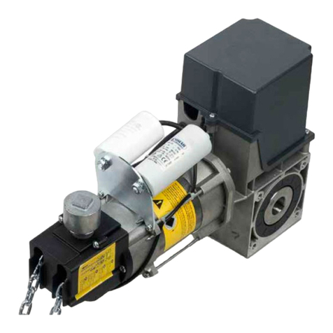
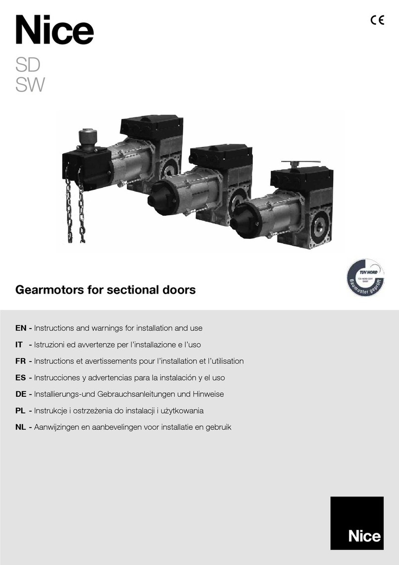
EN - Instructions and warnings for installation and use
Automation for sectional and rolling doors
Pro-H
NICE CANADA warrants that materials and workmanship are free from defects for a
period of two years from the date of invoice. Materials returned to Nice deemed defective after
examination will be returned at the option of Nice with repaired, new or re-manufactured parts.
NICE CANADA will not be responsible for any extra charges incurred in the process of
returning defective material. All returned material must be received pre-paid or it will not be
accepted.
This warranty is limited, and in lieu of all other warranties expressed or implied. There is no
expressed liability due on the part of the seller.

TAE  CNTENTS
AE













AANTY 
EIICATIN  EAT AN AAE 
SECIICATINS 
SAETY INSTCTINS 
INSTAATIN
EECTICA CNNECTINS AN SETTINS
IMIT SITC ASTMENT 
TEAM INSTAATIN INSTCTINS___________
CTC ASTMENT___
AE ASTMENT
EMEENCY MANA EATIN____
EAT MAINTENANCE 
MECANICA AINS AN ATS ISTS 
EECTICA IAAMS 
TINS
M  rive Chain and Sprockets
M ouble -belt reduction
M Chain Spreader   
M Chain Spreader   -
M igh Cycle modification
- aterproof modification
- Corrosion proof modification
- Explosion proof modification
M   olt control circuit
M  . sec time delay on reverse
M  Timer to Close
- Separate control panel
M ire release mechanism
M and Crank
 usher Springs
M- Auxiliary trolley cw track   chain
M- ual auxiliary trolley cw track   chain
M loor evel disconnect in lieu of chain keeper
Not available for logic board controls
 Standard feature with logic board controls
ANIN
 NT CNNECT T EECTICA E IN
INSTAATIN SEICIN  EAT


IMTANT
 ANY ESTINS CNCENIN TE SAETY  EATIN  TIS EAT EASE
CNTACT NICE AT --- SAE TESE INSTCTINS
pon delivery of your Nice heavy-duty ackshaft door operator, please inspect the unit carefully for damage. erify
that operator control wiring option, , voltage, phase and amperage correspond to available power supply and
door application. Check that along with your operator you have received the following standard hardware.
 x ENCSEST -button control station
 x  rive chain package   .m cw  connecting link
 x rive Sprocket  x  cw  set screws and  x - keyway
 x oor Sprocket  x  cw  set screws and  x - keyway
Note Sprocket sie and bore may vary according to
door sie and type, shaft sie and drum diameter
 x Chain keeper
 x eyring
 x  bolt, hex nut, lock washer and flat washer
 x pocket wheel hand chain (Model PRO-H)  x door height less  .m
 x arning sign
 set of Nice photocells supplied when operator ordered
with interface module or logic board controls
EIICATIN  EAT AN AAE

- and - heavy-duty ackshaft operators are designed for commercial and industrial high lift, vertical lift,
rolling doors and rolling grilles provided that doors are driven by a drive shaft. Model - is essentially the same as
model - with the exception that the - operator incorporates a chain hoist for manual operation of the
door.
STANA EAT EIT - S
MT Continuous duty  M industrial type motor. Note  M for  motors
-uilt-in overload protection -phase or separate full overload protection -phase.
-orsepower , , 
-oltage  -phase 
 -phase 
 -phase  
 -phase 
 -phase 
ECTIN rimary  -belt and pulleys  to  diameter. Secondary  chain and sprockets
TT SAT SEE  M
AE TINA Solenoid actuated drum and brake shoe braking system to prevent coasting and maintain door
position.
IIN TYE  TINS
ption  ull eature logic board Smart .   compliant. Note Nice compatible primary entrapment
device must be connected for , T or TS momentary or timer activation on close feature.
ption  elay logic controls with Interface Module   compliant. C Standard factory wiring constant
pressure on close, momentary contact on open and stop. If momentary contact on close  wiring is
desired, move white wire from terminal  to terminal . Note Nice compatible primary entrapment device
must be connected for  momentary activation on close or for T timer to close feature.
ption  Standard relay logic controls not   compliant, not available in S C- iring constant pressure
on close, momentary contact on open and stop. NTE If momentary contact on close  wiring is
desired, move white wire from terminal  to terminal .
TANSME AC control circuit, supplies power to drive logic board or control relays with A power available
for external devices.
IMIT ASTMENT  micro switches that control door travel. These limit switches are activated by fully adustable
screw type cams.
EMEENCY ISCNNECT loor level cable disconnect system with electrical cut-out feature allows person to
manually operate the door by hand - or by chain hoist - in case of emergency.
CTC Adustable friction clutch to minimie damage to door operator, door or vehicles when obstruction occurs.
EAT IMENSINS
-, - SECIICATINS
115 -phase 6
230 1-phase 6

-EA AN  A INSTCTINS
-Never allow children to operate or play with door controls. eep the remote control where provided away from children.
-ersonnel should keep away from a door in motion and keep the moving door in sight until it is completely closed or
opened. N NE S CSS TE AT  A MIN .
-Test the doors safety features at least once a month. After adusting the limit of travel, retest the door operators safety
features. ailure to adust the operator properly may cause severe inury or death.
-or products having a manual release, if possible, use the manual release only when the door is closed. se caution when
using this release when the door is open. eak or broken springs may cause the door to fall rapidly, causing severe inury
or death.
-EE S EY EATIN AN AANCE. See oor Manufacturers wners Manual. An improperly
operating or balanced door could cause severe inury or death. ave trained door systems technician make repairs to
cables, spring assemblies, and other hardware.
-ress the EN device or use emergency disconnect mechanism if a person is trapped under the door.
-SAE TESE INSTCTINS. The owner or users must understand the safety and operation of door system. Insure that
this installation manual be located close to the door system.
EA AN  A INSTAATIN INSTCTINS
-Commercial door operators are never to be installed on a residential installation
-Install only on a properly operating and balanced door. A door that is operating improperly could cause severe inury. ave
ualified service personnel make repairs to cables, spring assemblies, and other hardware before installing the operator.
-emove all pull ropes and remove, or make inoperative, all locks unless mechanically andor electrically interlocked to the
power unit that are connected to the door before installing the operator.
-Install the door operator at least  feet or more above the floor if the operator has exposed moving parts.
-o not connect the operator to the source of power until instructed to do so.
-ocate the control station a within sight of the door, b at a minimum height of  feet so that small children cannot reach
it, and
c away from all moving parts of the door.
-Install the Entrapment arning lacard next to the control station in a prominent location.
-or products having a manual release, instruct the end user on the operation of the manual release.
-Install non-contact entrapment protection devices photocells andor contact entrapment protection devices
reversing edges. Note photocells should be installed at no more than  from the floor. Edges should be installed
on the leading edge of the door.
IMTANT SAETY INSTCTINS
IMTANT INSTAATIN INSTCTINS
ANIN
T ECE TE IS  INY  EAT

Note
-Installation of operator must be done by a ualified installer. oor must be properly installed and working
smoothly. emove all door locks prior to installation.
-The - and - operators have dual output shafts and may be mounted on left standard or right
hand side of door. If handing of operator must be reversed, loosen set screws, remove drive sprocket and
keyway and install on opposite side of drive shaft.
or the - operator which incorporates a chain hoist mechanism the handing of the operator must be
stated at time of order. epending on installation, if handing of chain hoist is not correct the hand chain
may hang in door opening. If this is the case, swing chain off to the side and hook it over the top of the
door amb. o not attempt to reverse chain hoist on site.
. Install control station away from all moving door parts, within sight of the door and a minimum of  ft . m
from the ground.
. Install entrapment warning sign next to control station.
INSTAATIN INSTCTINS
ANIN
 NT INSTA TIS EAT
EE EAIN TIS MANA CAEY.

. As a general rule, the door operator should be installed below the drive shaft and as close to the door as possible.
The ideal distance between the operator drive shaft and the door shaft is approximately  cm to  cm. The
operator may be wallbench mounted or bracket shelf mounted. These two mounting configurations are shown
below
. Mount the operator to the wall, hood or bench with  bolts, nuts and washers provided or with lag bolts and
shields if installation reuires it. Make sure that operator is secured but do not tighten bolts.
. lace door sprocket on door shaft and align with operator drive sprocket but do not insert keyway or set screws.
. If an optional chain spreader has been ordered with your operator, install as shown below
. Install drive chain over sprockets, cut to a suitable length and connect with connecting link.
. ower or raise operator to adust chain tension so that there is no more than  chain slack between sprockets.
Tighten operator mounting bolts.
. Carefully re-align sprockets, if necessary and secure keyway and set screws.

. or - models Install hand chain by wrapping it through chain guard holes and pocket wheel. Allow
chain to hang down towards floor. Cut chain and connect so that chain is  to  from the floor.
. Install chain keeper to wall near hand chain at approximately  from floor. un disconnect chain through
keyhole of chain keeper and cut excess chain links if reuired. Attach keyring to end of disconnect chain.
. If an optional floor level disconnect lever was ordered in lieu of the chain keeper, mount to wall with suitable
hardware. Attach both chains together using keyring provided. Allow disconnect chain to be slightly slack
when lever is in the up position.

TEE AE  SSIE EECTICA CNT CNIATINS  TIS EAT
) tandard rela logic controls (not  () compliant not aailable in ) efer to Section A for
electrical connections. efer to electrical drawings inside your operator control box or generic drawings
MS- or MS- in the electrical drawings section at the end of this manual.
) Rela logic controls with nterface Module ( () compliant efer to Section  for electrical
connections. efer to electrical drawings inside your operator control box or generic drawings MS-IM-
 or MS-IM- in the electrical drawings section at the end of this manual.
) ull eature logic board mart  ( () compliant) efer to Section C for electrical
Connections and logic board instructions. efer to electrical drawings inside your operator control box or
generic drawings MS--, MS--, MS- or MSC- in the electrical
drawings section at the end of this manual.
efer to electrical diagrams inside control box cover or at the end of this manual prior to connection of power supply
or control station.
ANIN
T ECE TE IS  INY  EAT
A EECTICA CNNECTINS S E MAE Y A AIIE SEICE ESN
 NT ATTEMT T MAE EECTICA CNNECTINS T EAT NESS E
SY AS EEN ISCNNECTE AT SE 
EAT MST E CNNECTE IN ACCANCE T CA EECTICA CES AN
NE T EEN N  CATE INSIE CNT 
ANIN
CMAE AAIAE E SY TAE T EAT NAMEATE I
T EECTICA CNNECTIN. AIE T CNNECT AIATE E SY
TAE MAY CASE SEIS AMAE T EAT.
EECTICA CNNECTINS
IMTANT
-EAC INIIA CMMECIA  EAT MST AE ITS N
EICATE E SY
-NICE IY ECMMENS TAT EAC INIIA CMMECIA
 EAT AE AN ETENA CICIT EAE  SE
ISCNNECT

SECTIN A PRO- PRO-H tandard rela logic controls (not
 () compliant not aailable in )
E IIN se - . cm diameter holes for all power wiring.
. Single phase Connect single phase power supply to terminals  line and N on three-pole power
terminal strip.
. Three-phase Connect three phase power supply to terminals ,  and  on three-pole power terminal
strip.
CNT IIN se  . cm diameter holes for all control
wiring. Note o not run control wires and power wires in same conduit.
-Install control station within clear sight of door but away from all moving parts of door or hardware.
Install Entrapment warning sign next to control station. Connect -button openclosestop push
button station to terminals , ,  and . efer to electrical diagram for connection of two -
button stations.
NTE After electrical connections are made, manually move door to mid-position and, using the control station press the
pen button for several seconds and then press the Stop button. If door did not move in correct direction
verify wiring control station. or -phase operators, if door still moves in wrong direction reverse any two of the
three incoming power supply leads to correct rotation.
-Adust imit switches as explained in the imit switch adustment section further in this manual.
CNNECTIN  E SY AN CNT STATIN
IMIT SITC ASTMENT

. eversing Edge device must be normally open contact
Note If the door is controlled by any device or wired in such a manner that the door is not controlled by
constant pressure on close then an appropriate reversing edge must be installed.
. External interlock emove umper between terminals  and  and wire a N.C. interlock contact between these two
terminals.
. adio control receiver ire standard radio receiver to separate radio strip on side of control box or to terminals ,  and 
on control terminal strip inside control box.
. Single button openclose device ire to terminals  and  on control terminal strip.
. oop detectors, standard photocells with a N.. contact and other reversing devices ire to terminals  and  on
control terminal strip.
.  olt power ire to terminals  and  on control terminal strip
CNNECTIN  A EESIN EE EICE AN CNT ACCESSIES

SECTIN  PRO-(M) PRO-H(M) Rela logic controls with nterface
Module ( () compliant)
perator electrical connections and start-up instructions
Important ollow these steps carefully and in the order shown
 Connect ower supply
ingle phase Connect single phase power supply to terminals  and N on the -pole power
terminals strip. -phase Connect -phase power supply to terminals ,  and  on the -pole power
terminal strip.
 Connect ush-button station for installation purposes single phase or -phase
Connect openclosestop push button station to terminals T stop, T common, T open and T temporary C on close.
 erify motor direction
After the electrical power connections are made and push button station is connected, manually move the door to mid-
position. ress Close button for several seconds and then press stop button. If door did not move in correct direction
or if limit cams not moving in correct direction towards the close limit switch see below
NOTE: THIS OPERATOR COMES WITH AN INTERFACE MOUDLE INTEGRATED INTO THE
CONTROL CIRCUIT. THE PURPOSE OF THE INTERFACE MODULE IS TO ALLOW FOR FAILSAFE
MONITORING OF A NICE COMPATIBLE SAFETY DEVICE AS PER UL 325 (2010) REQUIREMENTS

ingle phase operators The operators leave the factory with correct motor and limit shaft direction according to
standard door installations. owever, for special fire door, thru- wall mounting or other special door applications, the
motor direction and limit switch direction may need to be reversed. To reverse the motor rotation, interchange black and
white wires going to motor on the reversing contactor.
-phase operators If door moves in wrong direction, turn off incoming power and reverse any two of the three incoming
power supply leads to correct rotation. ress the open button and then activate the open limit to ensure door stops.
If door does not stop, interchange grey and red wires on open and close limits. Interchange white and grey wires on
advanced open and advanced close limits. emove blue wire from advanced open limit and place it on N. pin of
advanced close limit.
 Adust limit switch cams
sing the openclosestop push button station move door to fully closed and fully open positions and set limit cams
to correct position. See imit adustment section  further in this manual for complete detail on the end of travel limit
adustments.
 Activate Interface module
After adusting the open and close limits and verifying the motor rotation, open the door to the full-open position using
the open push button igure below on left.
At this point the close pushbutton wire must now be moved from terminal T to T. Now connect the black wire
with blue label to terminal T as shown in figure below on right.
ote nsure the door is in the full open position before connecting the blac wire f door is not in full open position
and monitored photo-ees or safet edge are not connected and operational then door will immediatel moe in
the open direction

 Connect safety devices
ailsafe feature A monitored failsafe safety feature is built into the operator. The operator has provisions to
connect one primary monitored safety device as well as one or more non-monitored safety devices.
Primar monitored safet deice
Nice monitored failsafe photo beams or Nice compatible monitored failsafe devices must be connected to
terminals  and  if momentary close on pushbutton is reuired  mode. If not connected, door can only be
closed by constant pressure on close pushbutton. If constant pressure on close pushbutton is removed before
door reaches full closed position, then door reverses to full open.
ote Onl one monitored failsafe safet deice can be connected across terminals P and P
ote ee section  for complete installation instructions for the Nice - or the raba photocells
econdar non-monitored safet deice(s)
A standard -wire safety edge, non-monitored reflective or thru-beam photo eye or any other non-monitored
reversing devices with a N. dry contact can be connected to terminals S and S.
ote More than one secondar non-monitored safet deice can be connected to terminals  and 
mportant o not remoe resistor that is factor installed across terminals  and  unless installing a -wire electric
edge
-wire electric edge onnection
A standard -wire electric edge can be connected across S and S terminals as a secondary safety device. emove
the factory installed resistor across terminals S and S and install resistor across the black and white pair of wires from
the electric edge and connect the remaining black and white wire to the S and S terminals.
 Select Mode of peration
 mode of operation (momentar on open constant pressure on close)
The operator is wired at the factory for momentary on open and constant pressure on close. or commercial
operators, white wire is connected to terminal T.
 mode of operation (momentar on open momentar on close)
If momentary on close is reuired or commercial operators, remove the white wire from terminal T and place it on
terminal T.
The operator functions in  mode only when the primary monitored safety device is connected and functioning
properly. If it is not connected, operator will go into fault mode and door can only be closed by constant pressure
on close and if constant pressure on close is removed before door reaches full close position, door reverses to full
open.

SECTIN C PRO-() PRO-H() ull feature logic board mart 
( () compliant)
Note The operator is shipped from the factory in the  mode setting constant pressure open and close. The
operator should remain in this mode until all connections and limit switch adustments are completed.
E IIN INSTCTINS
Connect primary power supply directly to the separate power terminal strip supplied using any of the - . cm
diameter holes provided on control box. o not connect power supply directly to the circuit board.
. Single phase Connect single-phase power supply to terminals  and N on three-pole power terminal
strip  or  -phase.
. Three-phase Connect three-phase power supply to terminals ,  and  on three-pole power terminal strip
, , ,  or .
N A CS S INSTCTINS
n-board pen, Close and Stop buttons are provided directly on the board for installation and troubleshooting
purposes. In order to operate unit by on-board pen, Close, Stop buttons, the factory installed umper 
between the CM and ST terminals on the terminal strip must remain connected.
MT IECTIN EIICATIN
Make sure the mode of operation is selected to .
After electrical power connections are made, manually move door to mid-position. sing the on-board buttons press
the pen button for several seconds and then press the Stop button. If door did not move in correct direction or if
limit cams not moving in correct direction towards the open limit switch see below
or single-phase operators The operators leave the factory with correct motor and limit shaft direction according to
standard door installations. owever, for special fire door, through wall mounting or other special door applications, the
motor direction and limit switch direction may need to be reversed. A dipswitch ip  is provided to reverse direction
of motor and limit switch direction. If motor direction is reversed, the open and close limit switches are automatically
reversed. owever, the advanced close limit switch needs to be manually changed. isconnect the  wires from the
advanced closed limit switch and re-connect to the auxiliary limit switch provided.
Note Ensure that when the on-board open button is depressed and the door moves in the correct open direction that
activation of the open limit switch illuminates the EN IMIT .E. and stops the door.

or -phase operators If door moves in wrong direction, turn off incoming power and reverse any two of the three
incoming power supply leads to correct rotation. ress the on board open button again. If door is going in the correct
open direction, activate the open limit switch to ensure door stops. If door does not stop, turn off incoming power and
interchange any two incoming power lines once again and slide dipswitch  to reverse motor direction. If motor
direction is reversed, the open and close limit switches are automatically reversed. owever, the advanced close limit
switch needs to be manually changed. To do this, disconnect the  wires from the advanced limit switch and re-
connect to the auxiliary limit switch provided.
Note Ensure that when the on-board open button is depressed and the door moves in the correct open
direction that activation of the open limit switch illuminates the EN IMIT .E. and stops the door.
IMIT SITC ASTMENTS
nce the motor rotation and limit cam direction have been verified, adust the limit cam settings. lease note that
when each limit switch is activated the corresponding E will light up. efer to operator installation manual for
complete limit switch adustment instructions.
CNNECTIN  ETENA CS S
Connect CS S as shown in diagram.
Note umper  must be removed after the external CS S has been installed.
AISAE EATE
A safety device failsafe feature is built into the logic board. The logic board has provisions to connect one primary
monitored safety device as well as  or more secondary non-monitored safety devices.
rimary monitored safety device
Nice monitored failsafe photo beams or Nice compatible monitored failsafe devices must be connected to
terminals  and  as primary monitored safety device. rimary monitored safety device must be connected if
momentary activation on close is reuired in , T and TS modes. If it is not connected in , T and Ts modes,
door can only be closed by constant pressure on close and if constant pressure is removed before door reaches full
close position, door reverses to full open. Note nly one monitored failsafe device can be connected to terminals
 and .

Secondary non-monitored safety devices
A standard -wire safety edge, non-monitored photo beams or any other non-monitored reversing devices with a
N. contact can be connected to terminals S and S as secondary non-monitored safety device.
Note More than one secondary non-monitored safety device can be connected to terminals S and S.
Important o not remove the resistor that is factory installed across terminals S and S unless installing a -wire
electric edge.
-wire electric edge
A standard -wire electric edge can be connected across S and S terminals as a secondary safety device.
emove the factory-installed resistor across terminals S and S when using a -wire electric edge
CNNECTIN  ETENA SINE-TTN EICE
Connect an external single-button as shown in diagram. lease refer to Modes of operation for the functionality of
single-button.
MES  EATIN
All operators leave the factory in the  mode setting please read all modes of peration and determine which
operational mode is desired
 Momentary on open and close
•pen utton Momentary activation opens the door. hen door is closing, momentary activation reverses the door
EN EIE. Momentary contact from mid-stop opens the door to full open position. Constant activation when
door is opening, bypass mid-stop if enabled.
•Close button Momentary on close.
•Stop button Momentary activation stops the door.
•Single button device and single channel transmitter, -channel ,, transmitter
SE NCTIN penStopCloseeverse.
CMMECIA NCTIN penClose
everse.
•-button CS radio transmitter Same as open, close, stop buttons.
•Safety evices hen door is closing, momentary activation reverses the door.
•Timer to close NA

C Momentary open, constant pressure close
•pen utton Momentary activation opens the door. hen door is closing, momentary activation reverses the door
EN EIE. Momentary contact from mid-stop opens the door to full open position. Constant activation when
door is opening, bypass mid-stop if enabled.
•Close button Constant pressure on close. oor will stop when button is released
•Stop button Momentary activation stops the door.
•Single button device
SEENTIA NCTIN penStopConstant pressure on closestop.
CMMECIA NCTIN penConstant pressure on closestop.
•Single channel transmitter, -channel ,, transmitter and -button CS radio
transmitter Momentary activation opens the door. Momentary contact of EN button
on -button CS radio transmitter from mid-stop opens the door to full open position.
Cannot close the door.
•Safety evices hen door is closing, momentary activation reverses the door.
•Timer to close NA
 Constant pressure on open and close
•pen utton Constant pressure opens the door. oor stops when constant pressure is
released. Constant pressure from mid-stop opens the door to full open position.
•Close button Constant pressure on close. oor will stop when button is released
•Single button device, single channel transmitter, -channel ,, transmitter and -button
CS radio transmitter NA
•Safety evices hen door is closing, momentary activation reverses the door.
•Timer to close NA
E Momentary on open, constant pressure on close with roll-back feature
•pen utton Momentary activation opens the door. hen door is closing, momentary activation reverses the door.
Momentary contact from mid-stop opens the door to full open position. Constant activation when door is opening,
bypass mid-stop if enabled.
•Close button Constant pressure on close. oor reverses to full open when button is released.
•Single button
SEENTIA NCTIN penStopConstant pressure on closeStop.
CMMECIA NCTIN penConstant pressure on closeeverse.
•Single channel device, -channel ,, transmitter and -button CS radio
transmitter Momentary activation opens the door. Momentary contact of EN
button on -button openclosestop radio transmitter from mid-stop opens the door
to full open position. Cannot close the door.
•Safety evices hen door is closing, momentary activation reverses the door.
•Timer to close NA
T Momentary on open and close, timer to close, SAETY ACTIATIN  ST TTN
ISAE TIME
•pen utton Momentary activation opens the door. hen door is closing, momentary activation reverses the door.
Momentary contact from mid-stop opens the door to full open position. Momentary contact at full-open refreshes the
timer if enabled at full open. Momentary contact at full open position re-activates the timer if timer is disabled previously
by stop button or safety device. Constant activation when door is opening, bypass mid-stop if enabled.
•Close button Momentary on close.
•Stop button If door is opening or closing, momentary activation stops the door.
Momentary activation while timer is counting at mid-stop or full open de-activates the timer.
•Single button device, single channel and -channel ,, radio transmitter
SEENTIA NCTIN  penStopCloseeverse..
CMMECIA NCTIN peneverseefresh timer.
•-button CS transmitter Same as open, close, stop buttons.
•Safety evices hen door is closing, momentary activation reverses the door
to full open AN ISAES TIME.

•Timer to close Closes the door from mid-stop or full open. Momentary activation of stop button will de-activate the
timer. hen door is closing, momentary activation of safety devices will reverse the door to mid-stop if enabled or full
open and de-activates the timer. Timer resumes its normal operation upon momentary activation of open push button or
once the close cycle is completed. If mid-stop is enabled and Timer from mid-stop only dip-switch is N, timer is
enabled only from mid-stop and disabled from full open. If mid-stop is enabled and Timer from mid-stop only dip-
switch is , timer is enabled from full open and mid-stop.
TS Momentary on open and close, timer to close secure, ST TTN ISAES TIME
•pen utton Momentary activation opens the door. hen door is closing, momentary activation reverses the door.
Momentary contact from mid-stop opens the door to full open position. Momentary contact at full-open refreshes the
timer if enabled at full open. Momentary contact at full open position re-activates the timer if timer has been disabled
previously by stop button. Constant activation when door is opening, bypass mid-stop if enabled.
•Close button Momentary on close.
•Stop button If door is opening or closing, momentary activation stops the door.
Momentary activation while timer is counting at mid-stop or full open de-activates the timer.
•Single button device, single channel transmitter and -channel ,, radio transmitter
SEENTIA NCTIN penStopCloseeverse.
CMMECIA NCTIN peneverseefresh timer.
•-button CS radio transmitter Same as open, close, stop buttons.
•Safety evices hen door is closing, momentary activation reverses the door.
Momentary activation refreshes the timer to close.
•Timer to close Closes the door from mid-stop or full open. Momentary activation of stop button will de-activate the
timer. Timer resumes its normal operation upon momentary activation of open push button or once the close cycle is
completed. If mid-stop is enabled and Timer from mid-stop only dip-switch is N, timer is enabled only from mid-
stop and disabled from full open. If mid-stop is enabled and Timer from mid-stop only dip-switch is , timer is
enabled from full open and mid-stop.
arning hen replacing the logic board in a single-phase operator,
Make sure that umper  is installed properly before operating the door.
ailure to do this will damage the logic board.
AMMIN INSTCTINS
NTE A AM NCTINS CAN E INITIATE Y TNIN TE
SEECT STIC T TE ESIE SETTIN AT ANY INT IN
EATIN ECET  TE MI ST and N TIME ME,AMMIN
MST STAT M TE  CSE SITIN.
N-TIME SET
un-timer is the maximum amount of time the motor will run upon receiving an
open or close command. The factory default value for run-timer is  seconds.
Note imits must be set prior to setting run timer
Modify the run-timer from factory default
. Close the door to full close position.
. Set the selector dial to un-timer position. The elay n Close Timer
E should blink.
. ress open button. ait until door reaches full open position. The run timer value is set
to the time taken for the door to travel from full close position to full open position plus 
seconds.
. Set the selector dial to the desired mode of operation.
Modify the run-timer to factory default
. Close the door to full close position.
. Set the selector dial to un-timer position.
. ress stop button. The run-timer is modified to the factory default value. Then set the selector dial to the
desired mode of operation.

This manual suits for next models

1

Other Nice Door Opening System manuals

Nice Giro Technical specifications

Nice

Nice Giro Technical specifications

Nice STX KIT Technical specifications

Nice

Nice STX KIT Technical specifications

Nice F210S Product manual

Nice

Nice F210S Product manual

Nice NDA001 Owner's manual

Nice

Nice NDA001 Owner's manual

Nice SWN Series Technical specifications

Nice

Nice SWN Series Technical specifications

Nice SUMO Product manual

Nice

Nice SUMO Product manual

Nice SD-70-20 3 400 Technical specifications

Nice

Nice SD-70-20 3 400 Technical specifications

Nice SPA2 Technical specifications

Nice

Nice SPA2 Technical specifications

Nice AVIO600 Technical specifications

Nice

Nice AVIO600 Technical specifications

Nice SD Series Technical specifications

Nice

Nice SD Series Technical specifications

Nice spido SP6000 Product manual

Nice

Nice spido SP6000 Product manual

Nice Spider 6060 Installer manual

Nice

Nice Spider 6060 Installer manual

Nice PLUS Series User manual

Nice

Nice PLUS Series User manual

Nice Pro-LT Technical specifications

Nice

Nice Pro-LT Technical specifications

Popular Door Opening System manuals by other brands

Bandini Industrie GI.BI.DI. FLOOR Series Instructions for installations

Bandini Industrie

Bandini Industrie GI.BI.DI. FLOOR Series Instructions for installations

Tormax 1102 Installation and service manual

Tormax

Tormax 1102 Installation and service manual

Sesamo PROSWING operating instructions

Sesamo

Sesamo PROSWING operating instructions

Richmond GTR061 user manual

Richmond

Richmond GTR061 user manual

Assa Abloy Corbin Russwin ED4000 Series installation instructions

Assa Abloy

Assa Abloy Corbin Russwin ED4000 Series installation instructions

Teckentrup dw 62-2ME Operating / Assembly Instructions & Installation Data

Teckentrup

Teckentrup dw 62-2ME Operating / Assembly Instructions & Installation Data

FlexiForce ISC-NL Installation & maintenance

FlexiForce

FlexiForce ISC-NL Installation & maintenance

Synergy Hardware S4803 Fixing instructions

Synergy Hardware

Synergy Hardware S4803 Fixing instructions

Assa Abloy Norton 1600 Series quick start guide

Assa Abloy

Assa Abloy Norton 1600 Series quick start guide

Astra 3000 Series installation instructions

Astra

Astra 3000 Series installation instructions

FAAC 750 Standard instruction manual

FAAC

FAAC 750 Standard instruction manual

Siemens 3VL9800-3A 0 Series operating instructions

Siemens

Siemens 3VL9800-3A 0 Series operating instructions

Pujol Receptor REV Variocode Installation and adjustment instructions

Pujol

Pujol Receptor REV Variocode Installation and adjustment instructions

Label T-NFC User instructions

Label

Label T-NFC User instructions

Glutz SD-L F 9365 Series Mounting and operating instructions

Glutz

Glutz SD-L F 9365 Series Mounting and operating instructions

Allegion interflex IF-241 manual

Allegion

Allegion interflex IF-241 manual

Gerreka TORO-I Quick installation and programming guide

Gerreka

Gerreka TORO-I Quick installation and programming guide

Brookfield Industries NB-2000-HD2 installation instructions

Brookfield Industries

Brookfield Industries NB-2000-HD2 installation instructions

manuals.online logo
manuals.online logoBrands
  • About & Mission
  • Contact us
  • Privacy Policy
  • Terms and Conditions

Copyright 2025 Manuals.Online. All Rights Reserved.