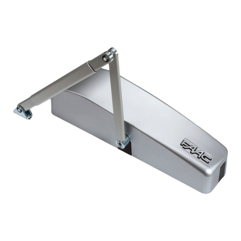
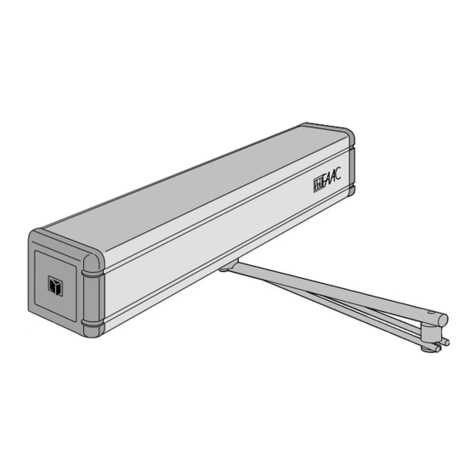
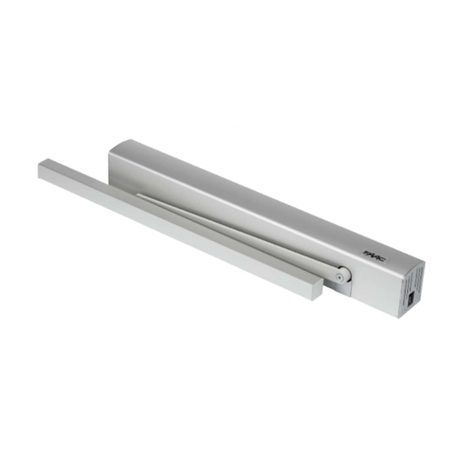
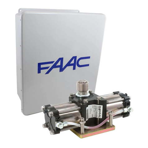
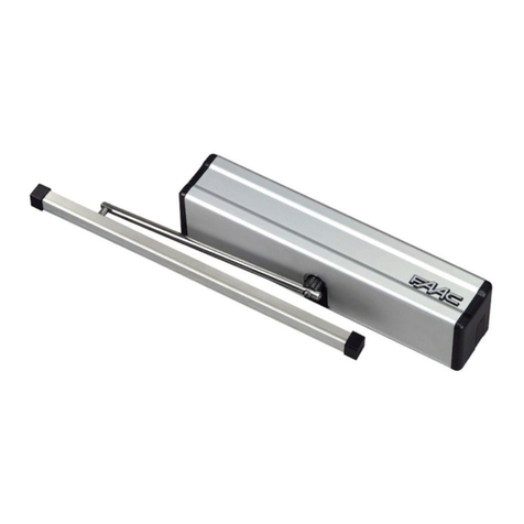
FAAC 950N User manual

950 N

950N 1 732708 - Rev. B
BRACCIO ARTICOLATO
ARTICULATED ARM
BRAS ARTICULÉ
BRAZO ARTICULADO
GELENKARM
KNIKARM
a
a
b
c
d
e
f
f
h
a
g
a
cc
a
OPEN
OPEN

950N 2 732708 - Rev. C
TAVOLA A : BRACCIOARTICOLATOA SPINGERE CON MONTAGGIO OPERATORE SULL’ARCHITRAVE
TABLE A : ARTICULATED PUSH ARM WITH OPERATOR INSTALLATION ON THE LINTEL
TABLE A: BRAS ARTICULÉ À POUSSÉE AVEC MONTAGE DE L’OPÉRATEUR SUR LE LINTEAU
LÁMINA A : BRAZO ARTICULADO DE EMPUJE CON MONTAJE DEL OPERADOR EN EL DINTEL
ÜBERSICHT A: DRUCKGELENKARM MIT MONTAGE DES ANTRIEBS AM STURZ
TEKENING A: KNIKARM MET DUWSYSTEEM MET MONTAGE AANDRIJVING OP DE BOVENDORPEL
a
OPEN
* Quota con albero standard 20 mm. Nel caso fosse necessario aumentare la distanza tra l’ope-
ratore ed il braccio, utilizzare le prolunghe opzionali ( Quota con albero 50 mm = 87 mm. - Quota
con albero 80 mm = 117 mm)
* Standard shaft dimension 20 mm. Should it become necessary to increase the distance between
the operator and the arm, use the optional extensions (dimension with 50 mm shaft = 87 mm - with
80 mm shaft = 117 mm)
* Cote avec arbre standard de 20 mm. S’il est nécessaire d’augmenter la distance entre l’opérateur
et le bras, utiliser les rallonges en option (Cote avec arbre de 50 mm = 87mm. - Cote avec arbre
de 80 mm = 117 mm)
* Cota con árbol estándar 20 mm. Si fuera necesario aumentar la distancia entre el operador y el
brazo, utilizar los alargues opcionales (Cota con árbol 50 mm = 87mm. - Cota con árbol 80 mm
= 117 mm)
* Maß mit Standardwelle 20 mm. Wenn der Abstand zwischen dem Antrieb und dem Arm erhöht
werden muss, die optionalen Verlängerungen verwenden (Maß mit 50-mm-Welle = 87 mm; Maß
mit 80-mm-Welle = 117 mm)
* Afstand met standaardas 20 mm. Indien de afstand tussen de aandrijving en de arm groter moet
zijn, gebruik dan de optionele verlengstukken (Afstand met as 50 mm = 87mm. - Afstand met as
80 mm = 117 mm)
b
0 - 15
0 - 15

950N 3 732708 - Rev. C
ITALIANO
* Quota con albero standard 20 mm. Nel caso fosse necessario aumentare la distanza tra l’ope-
ratore ed il braccio, utilizzare le prolunghe opzionali ( Quota con albero 50 mm = 87 mm. - Quota
con albero 80 mm = 117 mm)
* Standard shaft dimension 20 mm. Should it become necessary to increase the distance between
the operator and the arm, use the optional extensions (dimension with 50 mm shaft = 87 mm - with
80 mm shaft = 117 mm)
* Cote avec arbre standard de 20 mm. S’il est nécessaire d’augmenter la distance entre l’opérateur
et le bras, utiliser les rallonges en option (Cote avec arbre de 50 mm = 87mm. - Cote avec arbre
de 80 mm = 117 mm)
* Cota con árbol estándar 20 mm. Si fuera necesario aumentar la distancia entre el operador y el
brazo, utilizar los alargues opcionales (Cota con árbol 50 mm = 87mm. - Cota con árbol 80 mm
= 117 mm)
* Maß mit Standardwelle 20 mm. Wenn der Abstand zwischen dem Antrieb und dem Arm erhöht
werden muss, die optionalen Verlängerungen verwenden (Maß mit 50-mm-Welle = 87 mm; Maß
mit 80-mm-Welle = 117 mm)
* Afstand met standaardas 20 mm. Indien de afstand tussen de aandrijving en de arm groter moet
zijn, gebruik dan de optionele verlengstukken (Afstand met as 50 mm = 87mm. - Afstand met as
80 mm = 117 mm)
TAVOLA B : BRACCIO ARTICOLATO A SPINGERE CON MONTAGGIO OPERATORE SULLA PORTA
TABLE B : ARTICULATED PUSH ARM WITH OPERATOR INSTALLATION ON THE DOOR
TABLE B: BRAS ARTICULÉ À POUSSÉE AVEC MONTAGE DE L’OPÉRATEUR SUR LA PORTE
LÁMINA B : BRAZO ARTICULADO DE EMPUJE CON MONTAJE DEL OPERADOR EN LA PUERTA
ÜBERSICHT B: DRUCKGELENKARM MIT MONTAGE DES ANTRIEBS AM TOR
TEKENING B: KNIKARM MET DUWSYSTEEM MET MONTAGE AANDRIJVING OP DE DEUR
OPEN
c d
0 - 15
0 - 15

950N 4 732708 - Rev. C
BRACCIO A PATTINO
SLIDING ARM
BRAS À PATIN
BRAZO DE PATÍN
GLEITKUFENARM
ARM MET GLIJSCHOEN
a
a
b
e
d
d
f
f
g
i
h
j
k
OPEN

950N 5 732708 - Rev. C
ITALIANO
TAVOLA C : BRACCIO A PATTINO L=430 mm CON MONTAGGIO OPERATORE SULL’ARCHITRAVE
TABLE C : SLIDING ARM L=430 mm WITH OPERATOR INSTALLATION ON THE ARCHITRAVE
TABLE C: BRAS À PATIN L=430 mm AVEC MONTAGE DE L’OPÉRATEUR SUR LE LINTEAU
LÁMINA C: BRAZO DE PATÍN L=430 mm CON MONTAJE DEL OPERADOR EN EL DINTEL
ÜBERSICHT C : GLEITKUFENARM L = 430 mm MIT MONTAGE DES ANTRIEBS AM STURZ
TEKENING C: ARM MET GLIJSCHOEN L=430 mm MET MONTAGE AANDRIJVING OP DE BOVENDORPEL
OPEN
* Quota con albero standard 20 mm. Nel caso fosse necessario aumentare la distanza tra l’operatore ed il braccio,
utilizzare le prolunghe opzionali ( Quota con albero 50 mm = 107mm. - Quota con albero 80 mm = 137 mm)
* Standard shaft dimension 20 mm. Should it become necessary to increase the distance between the operator
and the arm, use the optional extensions (dimension with 50 mm shaft = 107 mm - with 80 mm shaft = 137 mm)
* Cote avec arbre standard de 20 mm. S’il est nécessaire d’augmenter la distance entre l’opérateur et le bras,
utiliser les rallonges en option (Cote avec arbre de 50 mm = 107mm. - Cote avec arbre de 80 mm = 137 mm)
* Cota con árbol estándar 20 mm. Si fuera necesario aumentar la distancia entre el operador y el brazo, utilizar
los alargues opcionales (Cota con árbol 50 mm = 107mm. - Cota con árbol 80 mm = 137 mm)
* Maß mit Standardwelle 20 mm. Wenn der Abstand zwischen dem Antrieb und dem Arm erhöht werden muss,
die optionalen Verlängerungen verwenden (Maß mit 50-mm-Welle = 107 mm; Maß mit 80-mm-Welle = 137 mm)
* Afstand met standaardas 20 mm. Indien de afstand tussen de aandrijving en de arm groter moet zijn, gebruik
dan de optionele verlengstukken (Afstand met as 50 mm = 107mm. - Afstand met as 80 mm = 137 mm)
e f

950N 6 732708 - Rev. C
TAVOLA D : BRACCIO A PATTINO L=330 mm CON MONTAGGIO OPERATORE SULL’ARCHITRAVE
TABLE D : SLIDING ARM L=330 mm WITH OPERATOR INSTALLATION ON THE ARCHITRAVE
TABLE D: BRAS À PATIN L=330 mm AVEC MONTAGE DE L’OPÉRATEUR SUR LE LINTEAU
LÁMINA D: BRAZO DE PATÍN L=330 mm CON MONTAJE DEL OPERADOR EN EL DINTEL
ÜBERSICHT D: GLEITKUFENARM L = 330 mm MIT MONTAGE DES ANTRIEBS AM STURZ
TEKENING D: ARM MET GLIJSCHOEN L=330 mm MET MONTAGE AANDRIJVING OP DE BOVENDORPEL
OPEN
* Quota con albero standard 20 mm. Nel caso fosse necessario aumentare la distanza tra l’operatore ed il braccio,
utilizzare le prolunghe opzionali ( Quota con albero 50 mm = 107mm. - Quota con albero 80 mm = 137 mm)
* Standard shaft dimension 20 mm. Should it become necessary to increase the distance between the operator
and the arm, use the optional extensions (dimension with 50 mm shaft = 107 mm - with 80 mm shaft = 137 mm)
* Cote avec arbre standard de 20 mm. S’il est nécessaire d’augmenter la distance entre l’opérateur et le bras,
utiliser les rallonges en option (Cote avec arbre de 50 mm = 107mm. - Cote avec arbre de 80 mm = 137 mm)
* Cota con árbol estándar 20 mm. Si fuera necesario aumentar la distancia entre el operador y el brazo, utilizar
los alargues opcionales (Cota con árbol 50 mm = 107mm. - Cota con árbol 80 mm = 137 mm)
* Maß mit Standardwelle 20 mm. Wenn der Abstand zwischen dem Antrieb und dem Arm erhöht werden muss,
die optionalen Verlängerungen verwenden (Maß mit 50-mm-Welle = 107 mm; Maß mit 80-mm-Welle = 137 mm)
* Afstand met standaardas 20 mm. Indien de afstand tussen de aandrijving en de arm groter moet zijn, gebruik
dan de optionele verlengstukken (Afstand met as 50 mm = 107mm. - Afstand met as 80 mm = 137 mm)
gh

950N 7 732708 - Rev. C
ENGLISH
1) ATTENTION! To ensure the safety of people, it is important that you read
all the following instructions. Incorrect installation or incorrect use of
the product could cause serious harm to people.
2) Carefully read the instructions before beginning to install the product.
3) Do not leave packing materials (plastic, polystyrene, etc.) within reach of
children as such materials are potential sources of danger.
4) Store these instructions for future reference.
5) This product was designed and built strictly for the use indicated in this
documentation. Any other use, not expressly indicated here, could compromise
the good condition/operation of the product and/or be a source of danger.
6) FAAC declines all liability caused by improper use or use other than that for
which the automated system was intended.
7) Do not install the equipment in an explosive atmosphere: the presence of
8) The mechanical parts must conform to the provisions of Standards EN 12604
and EN 12605.
For non-EU countries, to obtain an adequate level of safety, the Standards
mentioned above must be observed, in addition to national legal regulations.
9) FAAC is not responsible for failure to observe GoodTechnique in the construction
of the closing elements to be motorised, or for any deformation that may occur
during use.
10) The installation must conform to Standards EN 12453 and EN 12445.
For non-EU countries, to obtain an adequate level of safety, the Standards
mentioned above must be observed, in addition to national legal regulations.
11) Before attempting any job on the system, cut out electrical power .
all-pole switch with contact opening distance of 3mm or greater. Use of a 6A
thermal breaker with all-pole circuit break is recommended.
of the system.
14) Make sure that the earthing system is perfectly constructed, and connect
metal parts of the means of the closure to it.
15) The automated system is supplied with an intrinsic anti-crushing safety device
consisting of a torque control. Nevertheless, its tripping threshold must be
16) The safety devices (EN 12978 standard) protect any danger areas against
mechanical movement Risks, such as crushing, dragging, and shearing.
17) Use of at least one indicator-light (e.g. FAACLIGHT ) is recommended for
every system, as well as a warning sign adequately secured to the frame
structure, in addition to the devices mentioned at point “16”.
automated system, if system components not produced by FAAC are used.
19) For maintenance, strictly use original parts by FAAC.
20) Do not in any way modify the components of the automated system.
21) The installer shall supply all information concerning manual operation of the
system in case of an emergency, and shall hand over to the user the warnings
handbook supplied with the product.
22) Do not allow children or adults to stay near the product while it is operating.
23) Keep remote controls or other pulse generators away from children, to prevent
the automated system from being activated involuntarily.
24) Transit is permitted only when the automated system is stationary.
25) The user must not attempt any kind of repair or direct action whatever and
the operator thrust force) and of the release devices.
WARNINGS FOR THE INSTALLER
GENERAL SAFETY OBLIGATIONS
Manufacturer: FAAC S.p.A.
Address: Via Calari, 10 - 40069 Zola Predosa BOLOGNA - ITALY
Declares that: The operator 950N
is built to be integrated into a machine or to be assembled with other machinery to create a machine
under the provisions of Directive 2006/42/EC
conforms to the essential safety requirements of the following EEC directives
2006/95/EC Low Voltage Directive
2004/108/EC Electromagnetic Compatibility Directive
Also declares that it is prohibited to put into service the machinery until the machine in which it will be integrated
Directive 2006/42/EEC and subsequent amendments.
Bologna, 20-10-2012
The Managing Director
A. Marcellan
CE DECLARATION OF CONFORMITY FOR MACHINES
(DIRECTIVE 2006/42/EC)

950N 8 732708 - Rev. C
ENGLISH
ITALIANO
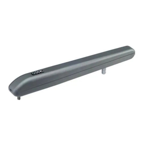
The 950 N automated system for leaf doors is an enbloc
consisting of an electromechanical device that allows door
opening by means of a transmission arm. The door closes
itself using a spring system.
The operator can be installed either on the architrave or
directly on the door structure.
The protective housing contains the electronic control unit
for system programming and operation control. The 950 N
operator is a reversible operator. Therefore, in the event of
power drop, the door can be opened manually.
Automated system
power supply
230 V~* or 115 V~*
(+6% -10%)
(* Depending on the model)
Absorbed power 100 W
Absorbed current 0,5 A
Electric motor 24 V= with encoder
Dimensions 530 x 105 x 160
L x H x D
Weight 10 Kg
Operating ambient
temperature
- 20° C..........+55°C
Protection
class
IP 23 (indoor use)
Maximum leaf
dimensions and
weight
Section 3
Use frequency continuous
ROT Continuous use at 55°C
Operation with
no power
manual push or pull opening
depending on the arm
Type of transmis-
sion arms
Articulated
Sliding L=330 mm
Sliding L=430 mm
Anti-crushing
device
With reverse in case of obstacle
(standard supply)
Maximum
opening angle
Section 3.3
950 N
2 DESCRIPTION AND TECHNICAL SPECIFICA-
TIONS
Opening
time
adjustable
from 4 to 10 seconds
Closing
time
adjustable
from 4 to 10 seconds
Accessories power
supply+ Electric
lock power supply
24 V =
1000mA max
Operating modes
(by selector switch)
Open - Automatic -
Manual or Night
Pause time adjustable
from 0 to 30 seconds
Modes adjustable
and 6
Terminal board
outputs
Board fault signal
Electric lock activation
Accessories power supply
Door status signal
Exchange relay controlled
from card reader
2-leaf connection signal
Signal for interlock between
two doors
Terminal board
inputs
Open commands
Emergency command
Key command
Card reader command
Fire-prevention command
STOP safety
Safety during closing
Rapid connectors
KP controller/SDK light
(optional)
Radio rp, minidec, decoder
board connector
Mode selector switch
connector
Mode selection Mode selector switch
KP controller
SDK light
1 PRELIMINARY CHECKS
For correct operation of the automated system, the existing door structure must feature the following:
1. Length and weight corresponding to the description contained in section 3.1
2. Max. post depth corresponding to the description contained in section 3.2
3. Sturdy and rigid leaf structure.
4. Existing hinges in good condition.
5. Smooth and even movement of the leaf, without irregular friction during the entire stroke.
6. Door “neutral” position during the entire stroke. Should the door tend to close or open, check the alignment of the hinges.
7. Presence of mechanical limit switches.

950N 9 732708 - Rev. C
a
i
h
df
k
j
g
e
c
b
l
m
e
n
ENGLISH
1. Cable routing holes
2.
3. 950 I/O unit
4. Mechanical stops adjustment
5. Motion transmission shaft coupling
6. Drive unit and return spring
7. Electric motor
8. 950 MPS programming unit
9. Transformer
10. Mains power supply terminal board
11. Housing securing bracket
12. Earthing terminal
13. Power supply cable securing terminal
14. Extension coupling (standard height 20 mm; 50 or
80 mm optional)
3 APPLICATION LIMITS
LEAF
LENGTH
(mm)
MAX LEAF WEIGHT (Kg)
ARTICULA-
TED PUSH
ARM
SLIDING
ARM
L=330 mm
SLIDING
ARM
L=430 mm
700 367 286
750 320 249
800 281 219
850 249 194
900 222 173
950 199 155
1000 180 140
1050 163 127
1100 149 116
1150 136 106
1200 125 97
1250 115 90
1300 107 83
1350 99 77
1400 92 71
MAXIMUM
DOORPOST
DEPTH
(mm)
3.1 APPLICATION LIMITSDEPENDINGON LEAFWEIGHT
AND LENGTH
3.2 MAXIMUM DOORPOST DEPTH
TABLE A TABLE B
ARTICULATED
ARM
Outward
opening
ARTICULATED
ARM
Inward
opening
0 - 250 mm 0 - 160 mm
Fig.1
Fig.2
TABLE C TABLE D
SLIDING
ARM
L=430 mm
Inward
opening
SLIDING
ARM
L=330 mm
Inward
opening
0 - 160 mm 0-160 mm

950N 10 732708 - Rev. C
ENGLISH
ITALIANO
1) With regard to the operator securing position (on the
architrave or door) and the type of arm used (push or sliding)
refer to the corresponding installation Table and drill the
holes required for securing the operator and the pull arm.
Please note: The two intermediate operator securing holes
are not centred (see installation Tables). The offset holes
make it possible to secure the operator in the correct sense
of rotation of the mechanism. The installation Tables are
as follows:
Table. A: ARCHITRAVE INSTALLATION
(ARTICULATED
PUSH ARM): outward opening.
Table. B: DOOR INSTALLATION (ARTICULATED
PUSH ARM): inward opening.
Table. C: ARCHITRAVE INSTALLATION (SLIDING
ARM LENGTH 430 mm): inward opening.
Table. D: ARCHITRAVE INSTALLATION (SLIDING
ARM LENGTH 330 mm): inward opening.
housing, without tightening them completely.
4 INSTALLATION
4.1 SECURING THE OPERATOR
The architrave (or door) structure designed
for securing the operator must not be warped.
-The operator must be secured parallel with the
floor.
Should use of a sliding arm be required, in-
stall the transmission arm before securing the
operator to the architrave (see paragraph 4.2.2
or 4.2.3)
3.3 MAXIMUM DOOR OPENING ANGLE
ARTICULATED ARM
INSTALLATION
TYPE
DOORPOST
DEPTH (mm)
MAXIMUM
OPENING
ANGLE
Operator on
architrave
0 100°
125 110°
250 125°
Operator on door 0 100°
SLIDING ARM
INSTALLATION
TYPE
DOORPOST
DEPTH (mm)
MAXIMUM
OPENING
ANGLE
Operator on
architrave
arm
L=430 mm
0 90°
160 105°
Operator on
architrave
arm
L=330 mm
0 90°
160 90°
3) Secure the operator using the six M6 screws and washers
in the previously drilled holes, as per the drilling templates
4.2 INSTALLING THE TRANSMISSION ARMS
It is always advisable to adjust the
mechanical stops inside the opening/
closing operator so that they are occupied
when the leaf reaches its mechanical
stops.
4.2.1 INSTALLING THE ARTICULATED ARM
1) Close the door.
2) Release the telescopic arm aby loosening the coupling
screws to allow it to slide.
3) Secure the coupling b, to the operator motion
transmission shaft connection, using the provided screw g
so that the arm is installed perpendicular to the operator c.
4) Secure the arm cto the coupling busing the two
provided screws d.
Should a greater distance be required
between the operator and the arm, use the
shaft extensions, available as accessories,
until the desired distance is reached.
5) Turn the arm cuntil the arm ais perpendicular to the
closed door or architrave.
6) Secure the arm plate hto the door or to the architrave
using two M6 screws and washers.
7) Tighten the four screws fsecuring the telescopic arm
a.
8) Manually verify that the door freely opens and closes
completely and stops on the leaf mechanical stop.
Important: The two transmission arms must never touch
each other.
4.2.2 INSTALLING THE SLIDING ARM
(inward opening)
IMPORTANT: When installing an sliding
arm, before powering the system, set
micro-switch nr. 2 to ON.
Install the arm gon the transmission
shaft before securing the operator to the
architrave.
1) Insert the screw hin the coupling f .
2) Secure the arm gto the coupling f using the two
provided screws i.
3) Insert the coupling fon the operator transmission shaft
so that the arm is secured at a 45° angle outward.
4) Tighten the operator screw h.
Should a greater distance be required
between the operator and the arm, use the
shaft extensions, available as accessories,
until the desired distance is reached
5) Screw the part f to the arm g .
6) Insert the part einto the part f and join them using
a Seeger ring k

950N 11 732708 - Rev. C
ENGLISH
For electrical cable installation, use adequate rigid and/or flexible tubes. Always separate the
low-voltage accessories connection cables from the power supply cables. To avoid possible
interference, use separate sheathing.
5 ELECTRICAL PREPARATIONS
1. 950 N Operator
2. Microwave radar / Passive infrared sensor
3. Key release for external use (KEY command)
4. Emergency open/close button
5. KP-CONTROLLER programming unit (optional)
6. KP-CONTROLLER locking key switch (optional)
7. Electric lock 24V= max 0.5 A
8. Shunt box
tubes/couplings, available commercially.
Fig.3
7) Assemble the sliding block dwith the springs j
b .
9) Manually pull the arm ginward and secure the track to
the closed door using two M6 screws.
10) Insert the two lateral plugs a in the track.
11) Manually verify that the door freely opens and closes
completely and stops on the mechanical stops.

950N 12 732708 - Rev. C
950 MPS
ENGLISH
6 PROGRAMMING THE 950 MPS BOARD
DS1 950 MPS SETTING
N° FUNCTION OFF ON NOTE
1
Final closing stroke Disabled Enabled
When the door is in “closed”
position, allows enabling of a
further
electric locks)
2
Set-up procedure
Articulated arm and/
or openings up
to 90°
Sliding arm and/
or openings
greater than 90°
3 External selector switch in
position 2
Position 2
set on
Manual
Position 2
set on
Night
Allows to decide which mode is to
be associated to position 2 of the
external selector switch
4
Push and go Disabled Enabled
By setting the external selector
switch to 0 (automatic), if the door
is pushed or pulled in opening
direction, it will open.
5 Leaf delay at opening
(master/slave application)
Disabled Enabled
6 Not used
7
STOP safety detection
space
(Terminal 14
950 I/O board)
Active during the
entire stroke
Active up to 70°
opening of the
door
If set to ON, the STOP safety is
monitored by a sensor installed on
the door and avoids the detection
of any obstacles beyond 70°
opening (e.g. side wall).
8
SCP
(Selectable Close Powe-
ring)
Additional force before
closing
Disabled Enabled
When this function is enabled, it
reduces the sensitivity of the
electronic anti-crushing device.
The activation of this function is
useful whenever high friction,
particularly hard door gaskets or
are present.
9 Not used
10 Board updating using the
RS232 port Disabled Enabled
Allows enabling of the RS232
port for connection with the PC to
Fig.4

950N 13 732708 - Rev. C
ENGLISH
ITALIANO
950 MPS BOARD LEDs
LD1 Green LED indicating
the electric motor power
LD2 Red signal LED:
LD3 Green LED for 5 V = power supply
950 MPS BOARD TRIMMERS
TR 1 Opening time adjustment
( 4 - 10 seconds )
TR 2 Closing time adjustment
( 4 - 10 seconds )
TR 3 Pause time adjustment
( 0 - 30 seconds )
950 MPS BOARD CONNECTORS
J1 24V= connector
J2 RS232 connector
J4 Connector for connecting to the 950 I/0 board
J5 Motor connector
Fig.5

950N 14 732708 - Rev. C
950 I/0
ENGLISH
7 PROGRAMMING AND DESCRIPTION OF THE 950 I/O BOARD
950 I/O BOARD LEDs
LED ON OFF NOTE
LD1 Accessories power present No accessories power
LD2 Card reader active Card reader not active Signals the status of
input 17
LD3 Internal opening command active Internal opening sensor
not active
Signals the status of
input 10
LD4 External opening command active External opening sensor
not active
Signals the status of
input 11
LD5 Emergency command not active Emergency command active Signals the status of
input 12
LD6 STOP safety not active STOP safety active Signals the status of
input 13
LD7 Closing phase safety
not occupied
Closing phase safety
occupied
Signals the status of
input 14
LD8 Key command active Key command not active Signals the status of
input 15
LD9 Fire-prevention command active Fire-prevention command not
active
Signals the status of
input 16
BOLD PRINT INDICATES THE DEFAULT CONDITION WITH DOOR IN REST POSITION
SW1= SET-UP START BUTTON
950 I/O DS1 SETTING
N° FUNCTION OFF ON
1Pause time following opening using
the “push and go” function.
2
seconds
Value set in automatic mode (using TR3 or
KP controller trimmers)
2 Opening delay for door
with electric lock
200
milliseconds
500 milliseconds
J7 = COUPLING FOR RADIO RECEI-
VER (RP, MINIDEC, DECODER)
J10 = 950 MPS POWER CONNECTOR
J11 = RAPID CONNECTOR FOR STATUS
SIGNALS TO THE 950 MPS BOARD
Fig.6
J9 = MOTOR POWER INTERRUP-
TION TERMINAL

950N 15 732708 - Rev. C
ENGLISH
ITALIANO
950 O/I BOARD CONNECTORS
J1 Secondary for transformer
J2 Rapid connector for Manual/Night, Open, Automatic mode selector switch
J3 Connector for KP CONTROLLER programming unit
J5
1Common contact for electric lock
2Normally open contact for activating the electric lock (max contact capacity 0.5A 24V). The contact
will close following an open command, during the approximately 70° stroke and with the door in ma-
nual mode.
3Normally closed contact for activating the electric lock (max contact capacity 0.5A 24V). The contact
will open following an open command, during the approximately 70° stroke and with the door in ma-
nual mode.
4Door closed status (normally open contact, max 0.5A / 24V ).
The contact will close when the door is closed.
5Common contact for door status
6Door open status (normally open contact, max 0.5A / 24V ). The contact will close when the door is
opened.
J4
7-8 GND = control board power supply negative
9+ 24 V= control board power supply positive
10 Internal open command (normally open contact).
In night mode does not open door.
11 External open command (normally open contact).
In night mode does not open door.
12 Emergency command (normally closed contact). If open, it commands door closing (the mode can be
13 Safety command during closing phase (normally closed contact). If open during closing, it reverses
the opening motion. As long as it is open it inhibits closing.
14 STOP command (normally closed contact).
If open, it interrupts the motion and/or inhibits operation.
15 Key command (normally open contact).
If closed, it commands door opening in any mode.
16 Fire alarm command (normally open contact).
If closed, it commands door closing.
17 Command coming from the card reader positive (24V signal = between 17 and 18).
18-19 GND = control board power supply negative
J6
20 Exchanging relay - Common contact
21 Exchanging relay - (normally open contact). This output closes when the card reader input
is activated, for 2 seconds.
22 Exchanging relay - (normally closed contact). This output opens when the card reader input
is activated, for 2 seconds.
23 Board fault output - Common contact
24 Board fault output (normally open contact).
This output closes when there is a board fault (see section 11.3)
25 +24 V=
26 GND = control board power supply negative
27 Interblock output (see section 8.9)
28 “Two leaf” output (see section 8.8)
J9 Terminal for interrupting motor power (if interrupted, it cuts off power to the motor)

950N 16 732708 - Rev. C
J4
ENGLISH
GND
GND
+24 V=
INTERNAL OPEN COMMAND (n.o.)
EXTERNAL OPEN COMMAND (n.o.)
EMERGENCY COMMAND (n.c.)
SAFETY COMMAND DURING CLOSING (n.c.)
STOP COMMAND DURING OPENING AND CLOSING (n.c.)
KEY COMMAND (n.o.)
FIRE-PREVENTION COMMAND (n.o.)
CARD READER COMMAND
GND
GND
8 950 I/0 BOARD ELECTRICAL WIRING
CARD READER INPUT
(24 V= signal)
+
-
8.1 COMMAND INPUTS
950 I/0
Fig.8
Fig.7

950N 17 732708 - Rev. C
+
-
C
+
-
C
+
-Tx Rx
J4
J5 J4
ENGLISH
/0
ITALIANO
PB SENSOR
PHOTOCELLS
ELECTRIC LOCK
24 V=
8.2 SAFETY INPUTS
8.3 ELECTRICAL LOCK COMMAND OUTPUT
TX=PHOTOCELLTRANSMITTER
RX= PHOTOCELL RECEIVER
PB SENSOR = STOP SENSOR
N.O.
950 I/0
950 I/0
Fig.9
Fig.10

950N 18 732708 - Rev. C
J5 J4
J5
22 23 24 25
J6
950 I/0
950 I/0
950 I/0
ENGLISH ITALIANO
ELECTROMAGNET
24V=
OPEN DOOR N.O. CONTACT
(Closes when the door is open)
CLOSED DOOR N.O. CONTACT
(Closes when the door is closed)
BOARD FAULT OUTPUT N.O. CONTACT
(It closes when an automated system fault is active)
8.4 ELECTROMAGNET COMMAND OUTPUT
8.5 DOOR STATUS OUTPUT (Max contact capacity 0.5 A / 24 V=)
8.6 BOARD FAULT OUTPUT (Max contact capacity 0.5 A / 24 V=)
Fig.11
Fig.12
Fig.13
N.C.

950N 19 732708 - Rev. C
20 21 22
1
0
2
950 I/0
ENGLISH
CARD READER INPUT N.C.
CONTACT
(Opens when the card reader
input is active)
CARD READER INPUT
N.O. CONTACT
(Closes when the card
reader input is active)
9 MODE SELECTION
SELECTOR
POSITION
MODE DESCRIPTION
1DOOR OPEN When this mode is selected, the door opens and stays open.
0AUTOMATIC
When this mode is selected, and when an internal/external command is acti-
vated, the door will open and close again after the pause time.
2
DIP N° 3 ON
MANUAL
The door can be opened manually (the lock, if present, will remain inactive)
2
DIP N°3 OFF
NIGHT
The external and internal commands are inactive. Door opening can be com-
manded only by activating the Key command.
The 950N operator features a 3-position mode selector switch (0-1-2) located on the side of the housing. The selector
switch must be set on a mode. The connection cable to the 950 I/O must be positioned so as to avoid damaging it.
If the kp controller or sdk light is used, the selector switch will have no effect on the automated
system.
8.7 CARD READER CONTACT OUTPUT (Max contact capacity 0.5 A / 24 V=)
Fig.14
Fig.17
Other manuals for 950N
1
Table of contents
Other FAAC Door Opening System manuals
Popular Door Opening System manuals by other brands

Dormakaba
Dormakaba ED 100 LE installation instructions

DITEC
DITEC DAS107PLUS user manual

DITEC
DITEC entrematic HA8-LP Installation instructions manual

Beninca
Beninca VN.S20 Operating instructions and spare parts catalogue

Verkada
Verkada AC62 install guide

Assa Abloy
Assa Abloy DC200 installation instructions