GENERAL DESCRIPTION
Each 8900 EMR series unit contains a door closer, hold
open electromagnet and smoke detector. The unit can be
used as a single installation or as a series of singles
powered from one or more power supplies. When a
series of 8900 EMR units are wired together in a run,
groups of up to 5 units may be interconnected.
Interconnection is accomplished through terminals #4
and #15 and results in all units alarming when any one
of them senses smoke. In turn, all associated hold
open electromagnets are de-energized. Within any run of
detectored units, it is permissible to form as many
interconnected groups as the total power supply
amperage will allow; but, again no more than 5 units
can be interconnected together.
Any detectored 8900 EMR series unit can be connected
to an auxiliary EMF non-detectored unit, or remote
detector, or both. It can be a single installation or part
of any of the multiple arrangements described above.
An auxiliary unit (double door applications) is a
companion to the main unit, and its electromagnet
de-energizes along with the main unit. A remote open
area detector sensing smoke alarms the 8900 EMR to
which it is connected and any other 8900 EMR to which
it is interconnected.
Single installations or groups of installations can be
connected to the alarm initiation circuit of a compatible
UL/ULC listed fire alarm control unit in 4-wire or 6-wire
configurations.
Additional functions are provided to separately power
the hold open electromagnets directly from the alarm
control panel as well as connections for a remote alarm
indicator lamp.
8900 EMR
(WITH DETECTOR)
INSPK NO. 08279530 Rev 08/13
INSTALLATION
1. Read entire instruction sheet prior to installation
and refer to NFPA 72E. Standards may be obtained
from THE NATIONAL FIRE PROTECTION
ASSOCIATION, Batterymarch Park, Quincy,
MA 02269.
2. Reference unit carton for unit mounting type.
3. Prepare door and frame for fasteners using the
appropriate template. Mark, drill, and tap holes as
indicated. If surface wiring is used, omit 7/8" hole
for wire access.
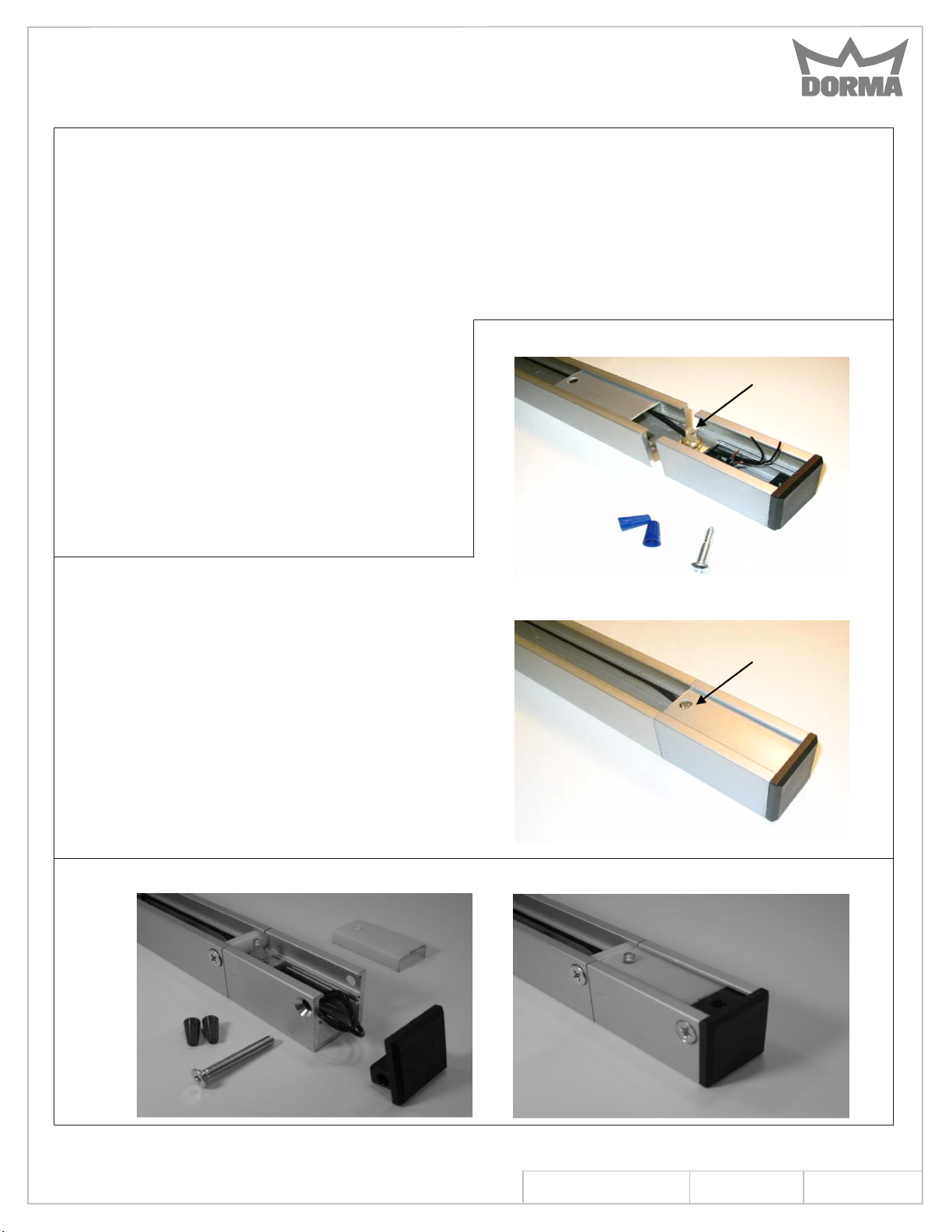
NOTE:
If installing the optional bypass switch, install assembly
on the end of track as shown. Fasten track to door frame
with the screw provided (T mount uses a cylindrical spacer).
Fasten the end cap assembly with metal or wood screws
provided. Connect the switch with wire nuts and slide the
cover in place. For T mount, place end cap in extension
piece and fasten to frame with screw provided.
Optional Bypass Switch - PT Mount
Optional Track Bypass Switch - T Mount
www.dorma-usa.com 1-800-523-8483
INS NO.
Rev.
08280990
08/13
PAGE
1 of 14


