English – 3
EN
ENGLISH
TUB4000
1
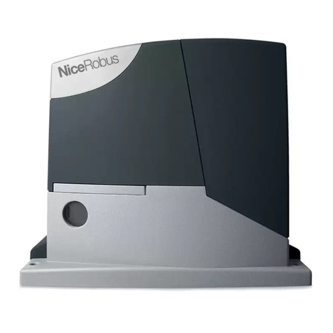
1PRODUCT DESCRIPTION AND INTENDED USE
TUB4000isaslidinggategearmotorofsignicantdimensionforindustrialuse,
withbuilt-incontrolunitDPRO500andisalsoprearrangedfortheinclusionof
NICE receivers.
The gear motor, which functions electrically, can be disengaged by means of a
key, thereby allowing the gate to be opened manually.
CAUTION! – All uses other than the intended use described and use
in environmental conditions other than those described in this manual
should be considered improper and forbidden!
2INSTALLATION
The TUB4000 must be installed exclusively by qualied technical
personnel in compliance with current laws, standards and regulations,
and with the instructions provided in this manual.
2.1 - Tests prior to installation
Before proceeding with installation, check the condition of the product com-
ponents, suitability of the selected model and conditions of the intended instal-
lationenvironment:
• Check that all the materials are in good working order and suited to the
intended use.
•Check that all conditions of use fall within the “application limits” of the
product(paragraph2.2)andthevaluelimitsshowninthe“Producttechnical
characteristics”.
• Check that the installation location is compatible with the overall dimensions
of the product (Fig. 1).
• Check that the surface chosen for installing the product is solid and can
ensure stable attachment.
•Makesurethattheinstallationareaisnotsubjecttoooding;ifnecessary,the
product may be installed, appropriately raised above ground level.
• Check that the space around the product allows safe and easy access.
•CheckthatallelectricalcablestobeusedbelongtothetypelistedinTable2.
• Check that the automation has mechanical stops in both the opening and
closing phases.
2.2 - Product application limits
The data relative to the TUB4000 performances is indicated in Chapter 13
(“Technicalspecications”)andistheonlydatathatallowsforcorrectlydeter-
mining whether the product is suitable for its intended use.
In general, TUB4000 is able to automate gates weighing up to 4,000 kg or up
to30mlong,accordingtothedatashowninTable1below.
TABLE 1
Length of leaf in metres Maximum cycles/hour
Up to 5 42
5÷10 21
10÷15 14
15÷20 10
20÷25 8
25÷30 7
0
0
5
10
15
20
25
30
35
40
10 15
L [m]
Cicli per ora
20 25 30
Graphic represen-
tation of the cycles
per hour in relation
to the length of the
gate leaf.
IMPORTANT!
Before performing any type of operation or
procedure, read carefully the general instructions
(page 1) and the application limits (paragraph 2.2)
Cycles per hour
Instructions translated from Italian
Contents
GENERALWARNINGS:SAFETY-INSTALLATION-USE ...............................................1
1-PRODUCTDESCRIPTIONANDINTENDEDUSE......................................................3
2-INSTALLATION........................................................................................................... 3
2.1-Testspriortoinstallation.................................................................................................................3
2.2-Productapplicationlimits ............................................................................................................... 3
2.3-Typicalsystem ...............................................................................................................................4
2.4-Installationofthegearmotor ........................................................................................................ 4
2.5-Installationofthevariousdevicestothecontrolunit ..................................................................... 4
3-ELECTRICALCONNECTIONS ................................................................................... 5
4 - TESTING AND COMMISSIONING.............................................................................. 7
4.1 - Testing ........................................................................................................................................... 7
5-INTEGRATEDCONTROLUNITDPRO500 ................................................................. 8
5.1 - Product description and intended use ........................................................................................... 8
6-INSTALLATION........................................................................................................... 8
6.1-Testspriortoinstallation.................................................................................................................8
6.2-Productapplicationlimits ............................................................................................................... 8
6.3-Installationofthecontrolunit ......................................................................................................... 8
7-ELECTRICALCONNECTIONS ................................................................................... 9
7.1 - Connecting the three-phase power supply cable ..........................................................................9
7.2-Connectingthesingle-phasepowersupplycable ..........................................................................9
7.3-Changingthepowersupplythroughthejumper ............................................................................9
7.4-Descriptionoftheelectricalconnections:powersupply,safetyandcontroldevices,
and accessories ............................................................................................................................ 9
7.5 - Electrical connections of the control unit .....................................................................................10
7.6-STOPSAFETYEDGEInput ........................................................................................................12
7.7 - Connecting a radio receiver .........................................................................................................12
7.8-Initialstartupandelectricalconnectionstest ................................................................................12
7.9-Totaldeletionofthecontrolunitmemory .....................................................................................12
7.10-RecognitionoftheconnecteddevicesandtheOpeningandClosingpositions..........................12
7.10.1 - Recognition of the Opening and Closing positions with mechanical limit switch......................13
7.11 - Operating modes .......................................................................................................................13
7.12-Oviewprogrammingunit ...........................................................................................................13
8-TESTINGANDCOMMISSIONING............................................................................14
8.1-Testing ......................................................................................................................................... 14
8.2-Commissioning ............................................................................................................................14
9-INSTALLATIONANDELECTRICALCONNECTIONOFTWOCONTROLUNITS
FORLEAVESMOVINGINOPPOSITEDIRECTIONS ................................................14
10-FURTHERDETAILSANDDIAGNOSTICS............................................................... 15
10.1-Furtherdetails ........................................................................................................................... 15
10.1.1 - Signals when switching ON ....................................................................................................15
10.1.2 - Other functions ....................................................................................................................... 15
10.2-Diagnostics ...............................................................................................................................16
11-BASICTROUBLESHOOTING................................................................................. 16
12-PRODUCTDISPOSAL ........................................................................................... 17
13-TECHNICALSPECIFICATIONS ..............................................................................17
CEDECLARATIONOFCONFORMITY...........................................................................18
USERGUIDE(detachableinsert) ................................................................................... 19
