Nichiryo Nichipet ECO User manual
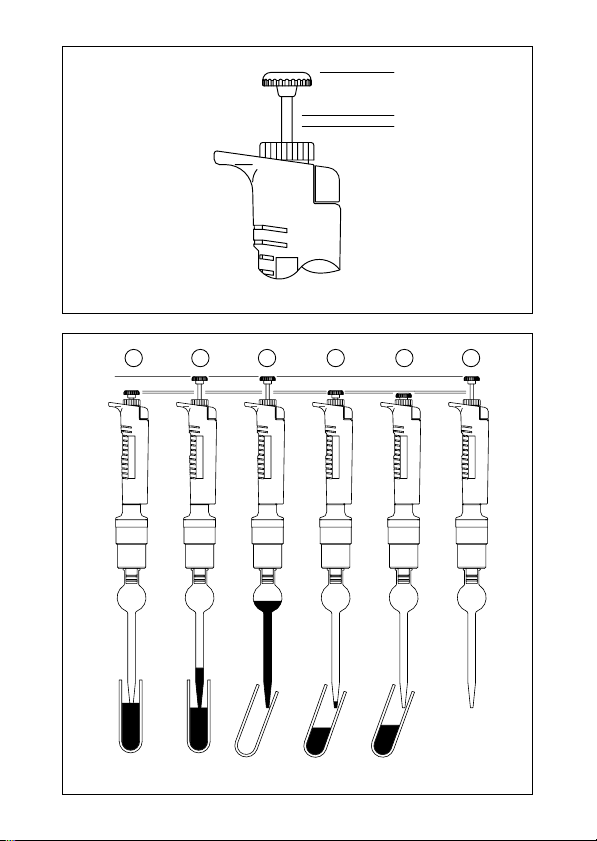
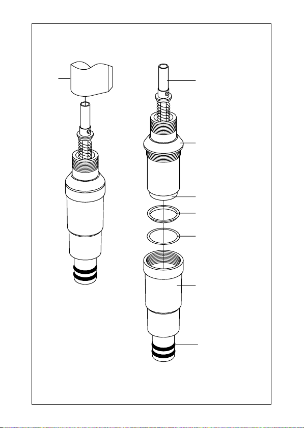
User's Manual
•Thank you for your purchase of our Nichipet ECO.
•Before proceeding to work with Nichipet ECO, carefully read this manual
for proper use of it.
Always Pursuing Originality
Since 1944
CERTIFIED
ISO9001
Pipette with Glass Tip for Endocrine Disruptors Research
Nichipet ECO
Nichipet ECO

– 1 –
Digital micro pipette for liquid handling
Features
●Glass Tip enables totally bias free liquid handling for endocrine disruptors analysis.
●Nozzle with double O-ring enables easy tip fitting/ejection and reliable sealing
secured.
●The sample volume can easily be set by simply turning the push button while
looking at the digital indication.
●The instrument has a special structure so that its precision is hardly affected by
the temperature of your hands if the instrument is used for long hours.
●Since PTFE (fluoroplastic) is used in the airtight chamber of the instrument, the
instrument keeps air tightness and precise reproducibility for long hours.
●Ceramic (plunger), PTFE (Tip holder), and FPM (O-ring) are used for liquid
contacting parts.
●Setting of the sample volume can be locked with locking mechanism so that the
volume does not easily change.
Standard accessories
●Glass tips ................ ×1
●O-rings for nozzle .... ×2
❋When unpacking the package, check to make sure that the above-mentioned
items are included.
Precautions on safety
●For using your Nichipet ECO properly and safely, carefully read "Precautions on
safety" in this paragraph and "CAUTIONS" on the next page before starting work
with it.
●The contents of "CAUTIONS" are matters that require the user's attention, not
only for using the Nichipet ECO properly but for preventing the user from accidents
and physical damage.
●After reading this manual, please keep it in a convenient place for refering to at
any time.
Nichipet ECO
Nichipet ECO

– 2 –
Please read the following prior to use for your safety and correct usage.
CAUTIONS
Be sure to observe the following instructions for using your
Nichipet ECO properly and safely.
If the user uses the Nichipet ECO in the wrong way, disregarding the following
instructions, it may result in injury to the user or/and other persons or physical damage
to this instrument or/and other equipment.
1. Don’t use this instrument for any purpose except pipetting / fractionzing liquid.
2. Don’t modify this instrument, because modification may cause an accident.
3. Don’t use this instrument for pipetting any liquid to be injected into the human
body.
4. Don’t discharge any sample liquid while pointing the instrument at anybody,
because some kinds of liquid are harmful to humans.
5. Firmly fit the tip to the nozzle, otherwise the tip may fall off and the inside sample
liquid may scatter.
6. Carefully handle the glass tips. They are very dangerous, if broken.
7. If the instrument is soiled with liquid harmful to the human body, immediately
take proper measures to clean it safely before proceeding with work.
8. When handling liquid harmful to the human body , be careful not to directly touch
the tip during or after use.
9. Don’t use this instrument for stirring liquid and so on, otherwise not only the tip
may be loose and fall off but the instrument may be soiled with the scattered
liquid.
10. Although this instrument has good chemical resistance in general, it may be
damaged by some kinds of chemicals such as N-methyl-pyrrolidinone etc.
When using a special chemical, please make enquires to our company.

– 3 –
Matters that require strict observance
Users are required to strictly observe
the following points in order for
the instrument to keep its excellent precision,
reproducibility and original performance for a long time.
1. Don’t expose this instrument directly to the sun when working with it or for 2
hours before starting work, otherwise the instrument may fail in precise pipetting.
Avoid working with this instrument in a humid and hot place.
2. Just before starting work with this instrument, avoid touching the tip and nozzle
cylinder as far as circumstances permit. If the nozzle cylinder is warmed by your
hand, it is hard to maintain accuracy.
3. For fractional pipetting, follow the forward method (the way explained in this
manual). If it is performed in a different way, it may result in inaccurate pipetting.
4. Operate the push button very gently. If it is quickly released, it may result in not
only inaccurate pipetting but also deterioration in the instrument, because the
sample liquid is sucked into the main body.
5. Don’t reuse a glass tip that has been used once without washing. If a glass tip is
repeatedly used, it may cause inaccurate and impure pipetting and cross
contamination (✽) among samples.
(✽) For example, if the previous sample liquid remains inside the tip, it is mixed
in with new sample liquid and the new sample is contaminated by the previous
one. Therefore, pipetting of the next sample ends with a wrong result. This
phenomenon is called mutual contamination of samples.
6. Don’t hold the instrument horizontally or upside down when there is liquid inside
the tip, otherwise the liquid gets into the main body and the instrument may
deteriorate.
7. When turning the push-button, don’t exceed the specified sample volume limit,
otherwise the instrument may be damaged or deteriorate.
8. Don’t perform pipetting with less liquid than the set volume. If the quantity of
liquid is less than the set volume, it may cause the liquid to scatter into the main
body and the instrument may deteriorate in quality.

– 4 –
Operating procedure
1. Setting the liquid volume
1) Turn the lock screw in the unlocking direction to loosen it. (Fig.A)
2) Turn the push button to set the digital counter to a desired liquid volume. To
increase the setting volume, turn the push button to pass the last set graduation
on the scale by half a turn and then set at the higher graduation as desired. To
decrease the setting volume, reset the digital counter directly at the lower gradu-
ation as desired. When setting the liquid volume, set the counter's graduation at
the point mark appearing in the lower part of the counter window. (Fig. B)
3) After setting the liquid volume, turn the lock screw in the locking direction to lock
it. (Fig. A)
Note: Don't exceed the specified liquid volume limit, otherwise the
instrument may be damaged or deteriorate in the quality.
2. Extracting liquid
1) Attach a glass tip to the nozzle.
2) Press the push button down from point "a" to the point "b". (Fig. C)
3) While depressing the push button, immerse the tip into the liquid to the extracting
volume (approximately 3 mm deep). (Fig. D-1)
4) Pull up the push button to point "a" to suck the liquid into the tip. With the tip still
immersed in the liquid, keep the instrument stationary for about 1 second to wait
untill the liquid is completely sucked into the tip. (Fig. D-2)
5) Gently extract the instrument to separate the tip from the liquid so that there are
no drops of liquid left on the outside of the tip. If there are some drops left on the
outside of the tip, wipe them off with a tissue, or the like, taking care not to touch
the tip.
Note: Don't extract liquid with the push button depressed at point "c"
shown in the Fig. C.
Note: Be careful to operate the push button very gently. If it is rapidly
released, the liquid may possibly be sucked into the main body
and pipetting may end with an inaccurate result.
3. Discharging the liquid
1) Gently place the tip on the inner wall of a proper vessel. (Fig. D-3)
2) Gently press the push button down from point "a" to point "b". Five seconds later,
press down the push button again from point "b" to point "c". The liquid is dis-
charged from the tip. (Fig. D-5)
When handling liquid harmful to humans, be careful not to touch
the tip during and after operation.

– 5 –
To lock
To unlock
Lock screw
Push button
0
1
0
0
0
0
0
1
Point mark
Nichipet ECO 1000µR
Digital counter 100~1000µR
Fig. A
Fig. B

– 6 –
a
b
c
1 2 3 4 5 6
Fig. C
Fig. D

– 7 –
Disassembling / Reassembling the airtight chamber
If such symptoms as mentioned in “Troubleshooting” (page12) occurs, disassemble
and inspect the instrument according to the following procedures.
1.Disassembling
1Turn the nozzle cylinder counterclockwise to remove it, as it is screwed into the
main body.
Note: When removing the nozzle cylinder, take care with the internal parts as
some of them occasionally spring out of the body (for types of 0.2mRR
RR
Rto
1mRR
RR
Rcapacity).
2Remove internal parts one after another
• 0.2mR,1mR:Fig. E
Remove the plunger, single spring, O-ring retainer, O-ring from the nozzle cylinder.
•5mR, 10mR: Fig. F, Fig. G
Remove the O-ring retainer and seal ring from the nozzle cylinder.
Note: Take care not to lose small parts during disassembling.
2. Reassembling
1Reassemble the nozzle cylinder.
• 0.2mR, 1mR: Fig. E
First set the single spring on the plunger, next set the O-ring retainer, O-ring in
this order.Then, insert the assembled plunger into the nozzle cylinder and screw
it into the body.
•5mR, 10mR: Fig. F, Fig. G
Set the seal ring, O-ring on the plunger in this order, and then insert the assembled
plunger into the nozzle cylinder while taking care that the O-ring does not come
off the center. After insertion, screw the nozzle cylinder into the body.
Note: When reassembling, be careful not to put the seal ring and O-ring in the
wrong order. If they put together in the wrong order, it not only affects
air tightness but causes liquid to leak, inaccuracy, failure in extracting
liquid, etc.
Note: After reassembling, repeat trial operation several times and check to
see that there is nothing wrong with the instrument.

– 8 –
Nozzle O-ring
^ Driver
Fig. H
3. Replacement for O-ring on nozzle
1Insert the O-ring replacing tool (such as a ^shaped driver) between the O-ring
and the nozzle. Remove the o-ring from the nozzle. (Fig. H)
2Attach the new O-rings to the nozzle.
Note: Be careful not to damage the nozzle when replacing O-rings with the
tool.

– 9 –
Nozzle cylinder
Nozzle O-ring
Body
Plunger head
Single spring
Plunger
O-ring retainer
Fig. E
200µ
RR
RR
R, 1000µ
RR
RR
R

– 10 –
Plunger head
Plunger assembly
Plunger
Seal ring
O-ring
Nozzle cylinder
Nozzle O-ring
Body
Fig. F
5000µ
RR
RR
R

– 11 –
Plunger head
Plunger assembly
Plunger
Seal ring
O-ring
Nozzle cylinder
Nozzle O-ring
Body
Fig. G
10mRR
RR
R

– 12 –
Troubleshooting
If there is still something wrong with the instrument after checking the above-mentioned
item, immediately stop using the instrument and ask us or our agent to repair it.
Before bringing the instrument for repair, be sure to check whether it has been polluted
with microbes or matter harmful to humans. In case it has been polluted, be sure to give
it a sterile treatment such as autoclaving.
The instrument fails to
extract liquid.
Extracted liquid leaks
from the tip.
The push button operates
poorly.
The nozzle cylinder has
come loose.
The O-ring / seal ring set
are assembled in the
wrong order.
The O-ring / seal ring set
are worn.
The nozzle cylinder has
come loose.
The nozzle cylinder is
worn (stepped wear can
be checked by eye.)
The O-ring / seal ring are
worm, because the
plunger is damaged or
rusty.
The tip is loosely attached.
The nozzle O-ring is worn
or damaged.
Liquid has been sucked
into the main body.
Try to screw the nozzle cylinder
firmly into the body again.
Reset the O-ring / seal ring
according to the instructions in
disassembling / reassembling
Replacement parts:
Purchase nozzle cylinder set for
0.2ml and 1ml for replacement.
PurchaseO-ring/seal ring set for
5ml and 10ml for replacement.
Screw the nozzle cylinder firmly
into the body again.
Replacement parts:
Purchase nozzle cylinder set for
0.2ml and 1ml for replacement.
Purchase nozzle cylinder for
5ml and 10ml for replacement.
Replacement parts:
Purchase plunger set or/and
nozzle cylinder set for 0.2ml and
1ml for replacement.
Purchase plunger assembly or/
and O-ring /seal ring set for 5ml
and 10ml for replacement.
Try to attach the tip to nozzle
tightly again.
Replace the nozzle O-ring with
new one.
If the push button does not work well just
after extracting liquid or it is just sticking to
the body, disassemble the instrument and
wash/clean every part (or wipe down every
part with a soft cloth). If there are some
parts getting rusty or corroded inside the
body, replace the parts with new ones by
purchasing optional replacement parts.

– 13 –
Code
Variable capacity
Measured volume
Accuracy Precision
(mRR
RR
R)(m
RR
RR
R)(%) (%)
00-NPC-200 0.02~0.2 0.02 ±6.0 <6.0
0.2 ±3.0 <3.0
00-NPC-1000 0.1~1.0 0.1 ±5.0 <5.0
1.0 ±3.0 <3.0
00-NPC-5000 1.0~5.0 1.0 ±5.0 <5.0
5.0 ±3.0 <3.0
00-NPC-10ML 1.0~10.0 1.0 ±6.0 <6.0
10.0 ±3.0 <3.0
Note: The value of accuracy and precision is made with distilled water at room
temperature 22°C~23°C
●Tip
Code Usable model Q’ty (box)
00-GLT-S 0.2mR00-NPC-200 10
00-GLT-L 1mR00-NPC-1000 10
00-GLT-X 5mR00-NPC-5000 10
00-GLT-Z 10mR00-NPC-10ML 10
●Replacement parts list (when placing order, make sure to
specify the capacity of each item.)
Name of replacement part Contents of set capacity Capacity (m
RR
RR
R)
1. Plunger set Plunger head / plunger 0.2mR
1mR
Plunger / Joint block 5mR
2. Plunger Assembly Joint plate 10mR
Joint shaft
3. Single spring Common
4. Nozzle cylinder 5mR, 10mR
5. Nozzle cylinder set Nozzle cylinder / O-ring 0.2mR
Seal ring 1mR
6. O-ring / Seal ring set O-ring / Seal ring 5mR,10mR
7. Nozzle O-ring Nozzle O-ring (2pcs) 0.2mR
8. Nozzle O-ring Nozzle O-ring (2pcs) 1mR
5mR,10mR
❋Specifications of the instruments and optional accessories as well as contents of
accessory sets are subject to change without notice.
❋No part of this manual may be reproduced/reprinted in any form without permission
of the copyright holder. The copyright law strictly prohibits this.

– 14 –
Inspection and Calibration Statement
The enclosed pipette was tested and calibrated under closely controlled
environmental conditions to ensure that it meets published calibration specifications.
The precision and accuracy results obtained for this pipette are provided on the
enclosed calibration certificate.
Because temperature and humidity conditions affect the calibration results of liquid
measurement devices, your pipette should be calibrated under conditions of use.
The calibration results obtained in your laboratory may vary from our results due to
differences in environmental testing conditions.

1-10-1 Kandanishiki-cho, Chiyoda-ku, Tokyo 101-0054, Japan
TEL: 81-3-6273-7652(English) FAX: +81-3-6273-7944
Homepage URL http://www.nichiryo.co.jp
E-mail [email protected]
MANUFACTURER:
For repair, service or information you may contact your local distributor.
2012.Ver.1
Table of contents
Other Nichiryo Laboratory Equipment manuals