Nieaf-Smitt EazyVolt Pro LED User manual

56
www.nieaf-smitt.com
EazyVolt Pro
LED & LCD
Voltage tester / Manual
Spanningstester / Handleiding
Spannungsprüfer / Bedienungsanleitung
Testeur de tension / Mode d’emploi
Comprobador / Manual de instrucciones
Testir de tensione / Manuale di instruzioni
6.1 & 6.2 EazyVolt Pro LED
6.3 & 6.4 EazyVolt Pro LCD
7.3 AC/DC V measurements
AC V
DC V
7.4 AC/DC low voltage measurements
7.5 Voltage interference suppression
(VIS)
11

55
www.nieaf-smitt.com
7.6 Continuity test
7.7 Diode test
7.8 Resistance test
7.9 Single pole phase test
AC V
7.10 Phase rotation test
Left
Right
7.11 RCD voltage test
7.12 Torch light
7.13 Frequency test (Pro LCD only)
7.14 Self test
7.15 NCV test

3
www.nieaf-smitt.com
Manual / Handleiding / Gebrauchanleitung / Mode
d’emploi / Manual de instrucciones / Manuale di
instruzioni
Page
English 4
Nederlands 13
Deutsch 22
Français 31
Español 40
Italiano 49
Version V001
Art.no. 561141243
MAN-EazyVolt Pro V1.0
Date 05-10-2018
Wabtec Netherlands B.V.
Vrieslantlaan 6
3526 AA Utrecht
T +31 (0)30 288 13 11
E sales.msbv@wabtec.com
I www.nieaf-smitt.com
Helpdesk:
I www.nieaf-smitt.nl/support
(c) Copyright 2018
All rights reserved. Nothing from this edition may be multiplied, or made public in any
form or manner, either electronically, mechanically, by photocopying, recording, or in
any manner, without prior written consent from Wabtec Netherlands B.V. This also applies
to accompanying drawings and diagrams. Due to a policy of continuous development
Wabtec Netherlands B.V. reserves the right to alter the equipment specication and
description outlined in this document without prior notice and no part of this publication
shall be deemed to be part of any contract for the equipment unless specically referred
to as an inclusion within such contract.

4
www.nieaf-smitt.com
EazyVolt Pro
Manual
Contents
Page
1. Safety 5
2. Symbols and features 5
3. Introduction 5
4. Safety measures 6
5. Danger of electric shock and other dangers 6
5.1 Intended use 7
6. Testers information 7
6.1 Device elements EazyVolt Pro LED 7
6.2 Display elements EazyVolt Pro LED 7
6.3 Device elements EazyVoltPro LCD 7
6.4 Display elements EazyVolt Pro LCD 7
7. Preparation for tests 7
7.1 Auto power on/ switching on 7
7.2 Auto power o 7
7.3 Voltage test 8
7.4 Low voltage mode 8
7.5 Voltage Interference Suppression (VIS) 8
7.6 Continuity test 8
7.7 Diode test 8
7.8 Resistance test (Pro LCD only) 9
7.9 Single-pole phase test 9
7.10 Phase rotation test 9
7.11 RCD test (Pro LCD only) 9
7.12 Torch light 9
7.13 Frequency (Pro LCD only) 10
7.14 Self test 10
7.15 NCV test (Pro LCD only) 10
7.16 HOLD function (Pro LCD only) 10
7.17 Backlight (Pro LCD only) 10
7.18 Battery replacement 10
8. Cleaning and storage 10
9. Maintenance 10
10. Warranty 11
11. Specications 11

5
www.nieaf-smitt.com
1 Safety
The instruction manual contains information and references,
necessary for safe operation and maintenance of the tester.
Prior to using the tester (commissioning/ assembly) the user is
kindly requested to thoroughly read the instruction manual
and comply with it in all sections.
Failure to read the tester manual or to comply with the warnings
and references contained herein can result in serious bodily injury or
tester damage.
The respective accident prevention regulations established by the
professional associations are to be strictly enforced at all times.
2 Symbols and features
Symbols as marked on the tester and instruction manual
The instrument complies with the valid directives. It complies with
the EMV Directive (2014/30/EU), Standard EN 61326-1 are fullled. It
also complies with the Low Voltage Directive (2014/35/EU), Standard
EN61243-3:2014 is fullled.
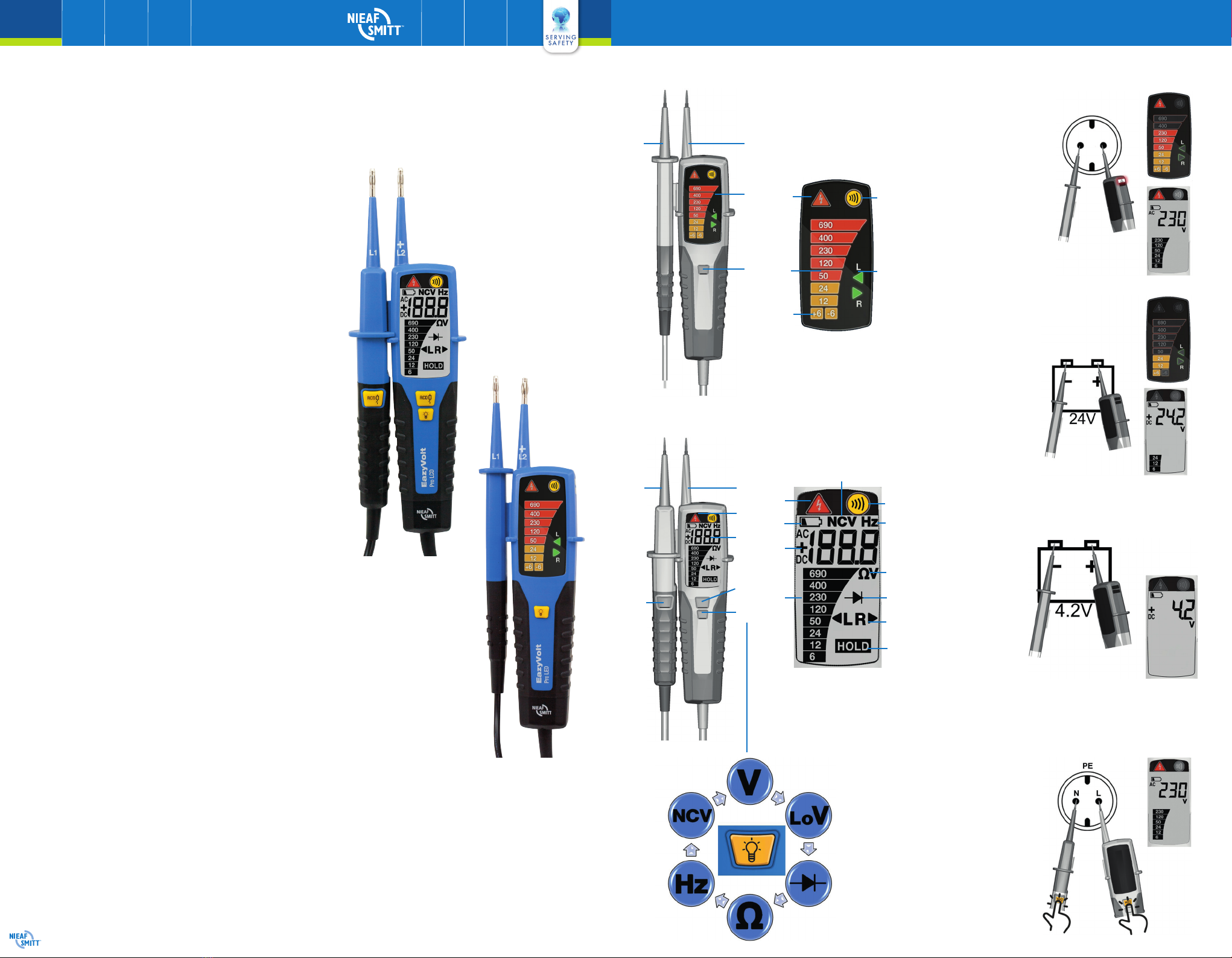
3 Introduction
The Nieaf-Smitt EazyVolt Pro voltage testers are universally applicable
testers for voltage testing continuity testing and rotary eld testing.
The testers are constructed according to the latest safety regulations
and guarantee safe and reliable working.
The EazyVolt Pro LED voltage testers are characterized by the follo-
wing features:
• Start voltage 6 V
• Polarity indication
• Continuity test
• Single-pole phase test
• Phase rotation test
• Torch light
• Side detection for ELV and Continuity
• AC and DC voltage test up to 690 V
• Auto-power ON / OFF
• IP 64
• CAT IV - 600 V
• Selectable measuring points 2-4 mm
• GS38 rubber protection caps
Extra on EazyVolt Pro LCD
• Digital readout via a large LCD display
• Multi-colour background illumination
• High resolution Voltage of 0.1 V (<30 V)
• High voltage AC (1000 V) and DC (1500 V)
• NCV (Non-Contact Voltage) detection
• RCD trip test (via 2-button activation)
• Diode test
• Voltage test with load
• Resistance measurement
• Frequency measurement
• Vibration motor for ELV
After unpacking, check that the instrument is undamaged.
The product package comprises:
1 x Tester EazyVolt Pro
2 x 4 mm test tip adapters
2 x GS38 rubber caps
2 x Batteries 1.5 V, IEC LR03
1 x Manual
Caution! Dangerous voltage. Danger of electrical shock
Warning of a potential danger, comply with instruction
manual
+ or - + DC or –DC measurement
Equipment protected by double or reinforced insulation
Conforms to EU directives
High Voltage Detection
Tester complies with the standard (2012/19/EU) WEEE

6
www.nieaf-smitt.com
4 Safety Measures
To ensure safe operation and service of the tester, follow these
instructions. Failure to observe warnings can result in severe
injury or death.
The testers have been constructed and tested in accordance with
the safety regulations for voltage testers and have left the factory
in a safe and perfect condition.
The operating instructions contain information and references
required for safe operation and use of the tester. Before using the
tester, read the operating instructions carefully and follow them
in all respects.
Depending on the internal impedance of the voltage detector
there will be a dierent capability of indicating the presence or
absence of operating voltage in case of the presence of interfe-
rence voltage.
A voltage detector of relatively low internal impedance,
compared to the reference value of 100 kΩ, will not indicate all
interference voltages having an original voltage value above the
ELV level. When in contact with the parts to be tested, the voltage
detector may discharge temporarily the interference voltage to a
level below the ELV, but it will be back to the original value when
the voltage detector is removed.
When the indication“voltage present” does not appear, it is hig-
hly recommended installing earthing equipment before work.
A voltage detector of relatively high internal impedance, com-
pared to the reference value of 100 kΩ, may not permit to clearly
indicate the absence of operating voltage in case of presence of
interference voltage.
When the indication“voltage present” appears on a part that
is expected to be disconnected of the installation, it is highly
recommended conrming by another means (e.g. use of an ade-
quate voltage detector, visual check of the disconnecting point
of the electric circuit, etc.) that there is no operating voltage on
the part to be tested and to conclude that the voltage indicated
by the voltage detector is an interference voltage.
A voltage detector declaring two values of internal impedance
has passed a performance test of managing interference voltages
and is (within technical limits) able to distinguish operating
voltage from interference voltage and has a means to directly or
indirectly indicate which type of voltage is present.
5 Danger of electric shock and other dangers
To avoid an electric shock, observe the precautions when wor-
king with voltages exceeding 120 VDC or 50 V e AC. In accor-
dance with EN 61243-3 these values represent the threshold
contact voltages.
The tester must not be used with the battery compartment open.
Before using the tester, ensure that the test lead and device are
in perfect working order. Check for broken cables or leaking
batteries.
Hold the tester and accessories by the designated grip areas only,
the display elements must not be covered. Never touch the test
probes.
The tester may be used only within the specied measurement
ranges and in low-voltage installations up to 690 V. (EazyVolt Pro
LCD up to 1000 VAC and 1500 VDC)
The tester may be used only in the measuring circuit category it
has been designed for.
Before and after use, always check that the tester is in perfect
working order (e.g. on a known voltage source).
The tester must no longer be used if one or more functions fail or
if no functionality is indicated.
It is not permitted to use the tester during rain or precipitation.
A perfect display is guaranteed only within a temperature range
of -15 °C to +55 °C at an relative air humidity less than 85 %.
If the safety of the user cannot be guaranteed, the tester must be
switched o and secured against unintentional use.

7
www.nieaf-smitt.com
Safety is no longer guaranteed e.g. in the following cases:
- obvious damage
- broken housing, cracks in housing
- if the tester can no longer perform the required measurements/
tests
- stored for too long in unfavourable conditions
- damaged during transport
- leaking batteries
The tester complies with all EMC regulations. Nevertheless it can
happen in rare cases that electric devices are disturbed by the
electrical eld of the tester or the tester is disturbed by electrical
devices.
Never use the tester in explosive environment
Tester must be operated by trained users only
Operational safety is no longer guaranteed if the tester is modi-
ed or altered.
The tester may be opened by an authorized service technician
only.
5.1 Intended Use
The tester may be used only under the conditions and for the
purposes for which it was designed. Therefore, observe in particular
the safety instructions, the technical data including environmental
conditions.
6 Testers Information
6.1 Device elements EazyVolt Pro LED
1. Test probe, L1 (-)
2. Torchlight button
3. LED indication
4. Test tip, L2 (+)
6.2 Display elements EazyVolt Pro LED
1. Single pole test; ELV warning
2. Voltage indication
3. LEDs indicating 6 V and polarity
4. Rotary eld - L(left) and R(right)
5. Buzzer/continuity LED (when blinking indicates low battery)
6.3 Device elements EazyVolt Pro LCD
1. Test probe, L1 (-)
2. RCD button
3. Torchlight/function button (function sequence: Voltage/Con-
tinuity Low voltage Diode test Resistance Frequency
NCV)
4. RCD button
5. LCD with backlight
6. LED indication
7. Test tip, L2 (+)
6.4 Display elements EazyVolt Pro LCD
1. Single Pole Test; ELV Warning
2. Battery symbol
3. Measured value (V, Ω or Hz)
4. Voltage indication
5. HOLD symbol (when hold function is active)
6. Rotary eld - L(left) and R(right)
7. Diode symbol (when diode mode is selected)
8. Ohm symbol (when resistance mode is active)
9. Hz symbol (when frequency mode is active)
10. Buzzer/continuity symbol
11. NCV (Non-Contact Voltage) Symbol (when NCV mode is active)
7 Preparation for tests
7.1 Auto-power-on/ switching on
• The tester switches on when it detects shorten tips, or an AC
or DC voltage above approx. 10 V or a live phase on + (single
pole test)
• It can be switched on with the button

8
www.nieaf-smitt.com
7.2 Auto-power o
• Tester is automatically powered o after approx.10 sec when
there is no signal contacted to the probes
• The torch light automatically switches o after approx. 30 sec.
7.3 Voltage test
• Connect both probes to the object under test
• The voltage is indicated by LED or LCD
- Buzzer sounds when a threshold voltage is >50 V AC/DC or
>120 VDC
- Vibration is ON when a threshold voltage is >50 VAC or
>120 VDC (EazyVolt Pro LCD only)
• Voltage polarity is indicated in following manner:
Pro LED
- AC: + and -6 V LED are both on
- +DC: +6 V LED is on
- - DC: -6 V LED is on
Pro LCD
- AC: AC symbol is on
- +DC: +DC symbol is on
- -DC: -DC symbol is on
Once the tester is powered on, it will automatically measure vol-
tage in the range of 6 V-690 V (Pro LED) and 6 V-1000 VAC/1500
VDC (Pro LCD in voltage/continuity mode) and 1 V-1000
VAC/1500 VDC (Pro LCD in low voltage mode)
When the L2 probe + is the positive (negative) potential, the
Polarity indication LED indicates ‘+DC’ (‘-DC’)
In case of empty batteries: 50/120/230/400/690 V LEDs still
indicate the presence of voltage (Pro LED) or the ELV LED lights
up >50 VAC, >120 VDC (Pro LCD)
7.4 Low Voltage mode (1 V-1000 VAC/1500 VDC - Pro LCD)
• Short press the button once to enter Low Voltage Mode, or
repeat short pressing until LO symbol is shown on LCD
• In Low Voltage mode it is possible to measure AC and DC
voltage from 1 V
• Connect both probes to the object under test
Continuity mode is disabled in Low Voltage Mode.
7.5 Voltage Interference Suppression (VIS)
• A voltage can be induced by a capacitive or inductive coupling
with a LIVE circuit. This could lead to an Interference Voltage
detection. By pressing the RCD/ LOAD button during an AC
voltage measurement the Pro LCD will apply a load to the system
to supress this Interference Voltage. A beeping sound will be
heard.
• This will increase the detection capability of the presence of
voltage
7.6 Continuity test
Make sure the object under test isn’t live.
• Connect both test probes to the object under test
- Continuity test is performed automatically except in Low
Voltage and Resistance mode of Pro LCD
- Buzzer/Continuity LED lights up and buzzer sounds
continuously to indicate continuity
- LCD display show Con Symbol to indicate continuity
- Tester switch to voltage measurement if voltage is
detected during continuity testing >6 V
This test is only possible when batteries are installed and in good
condition
7.7 Diode test
Make sure the object under test isn’t live.
• Switch into diode testing mode by short pressing two times
button or repeat short pressing until symbol is shown on
LCD. Connect both test probes to the diode under test

9
www.nieaf-smitt.com
- Continuity LED lights up, buzzer sounds continuously and
Con symbol on LCD is on if L1 tip is connected on Anode
of diode and L2 tip on Cathode
- Continuity indication will be o if L1 tip is connected on
Cathode of diode and L2 tip on Anode
- Tester switch to voltage measurement if voltage >6 V or
single pole is detected during diode testing
7.8 Resistance test (Pro LCD only)
Make sure the object under test isn’t live
• Switch into resistance measurement by short pressing 3 times
button or repeat short pressing until Ω symbol is shown on LCD.
Connect both test probes to the object under test. Resistance up
to 2000 Ω can be shown on LCD. For resistance less than ~30 Ω
buzzer sounds continuously to indicate low continuity.
Tester switch to voltage measurement if voltage >15 V or single
pole is detected
• The Resistance test is only possible when batteries are installed
and in good condition
7.9 Single-pole phase test
Function of this test may not be fully achieved if the insulation
condition/ grounding conditions of user or of the equipment
under test aren’t good enough. Verication of live-circuit
shouldn’t be dependent on this single-pole phase test only, but
on a 2-pole voltage test.
Firmly grasp the insulated grips of the main body of the tester in
order to increase the sensitivity of single-pole phase test.
Hold the tester good in your hand. Connect the ‘+’probe to the
object under test.
Live circuit LED lights up and buzzer sounds when a voltage of
approx. 100 VAC or more is detected on the object under test.
(Pol≥100 VAC).
Single pole indication is via LED
LCD backlight will be red if single pole is detected
The single-pole phase test is only possible when batteries are
installed and in good condition
7.10 Phase rotation test (EazyVolt Pro and EazyVolt Pro LCD)
• L LED (symbol) and R LED (symbol) for phase rotation test may
operate on various wiring systems, but eective testing result
can be obtained only on three-phase 4-wire system
• Firmly grasp the insulated grip of the tester probe L2, it is better
for the sensitivity of the phase rotation test and connect both
probes to the object under test
• Phase-to-phase voltage is indicated by voltage LEDs (Pro LED)
or LCD (Pro LCD)
• R LED lights up for Right rotary eld on EazyVolt Pro; R symbol
on LCD lights up for Right rotary eld on EazyVolt Pro LCD
L LED lights up for Left rotary eld on EazyVolt Pro; L symbol on
LCD lights up for Left rotary eld on EazyVolt Pro LCD
• Measurement principle: The instrument detects the phase
rising order regarding the user as earth.
• Testing of phase-sequence direction is possible from 100 VAC
voltage (phase to phase) provided the neutral is earthed
• Function of this test may not be fully achieved if the insulation
condition/ grounding conditions of user or of the equipment
under test is not good enough
7.11 RCD Test (Pro LCD only)
• Connect both test probes between L and PE
• Press both RCD buttons
• For voltage tests in systems with RCD (earth leakage circuit
breakers) an RCD can be tripped with a 10 mA or 30 mA
nominal leakage current on single phase AC 230 V power
system. The RCD should trip.
7.12 Torch light
• Press the button to turn on the light and after approx. 30 s it
will turn itself o
• Turning on of torch light will change operating mode on EazyVolt
Pro LCD

10
www.nieaf-smitt.com
7.13 Frequency test (Pro LCD only)
• Switch into frequency measurement by short pressing 4 times
the button or repeat short pressing until Hz symbol is
shown on LCD. Fr and Hz symbol should be on LCD. Connect
both test probes to the AC voltage under test. Frequency from
1 Hz to 800 Hz can be shown on LCD
Frequency measurement is possible for voltages >10 VAC
• The level of voltage will be shown only on the bar graph
7.14 Self test
• LEDs up to 50 V (Pro LED), all LCD segments and vibration
motor (Pro LCD), torch light, ELV indication and buzzer are
turned on for a second after battery replacement or selftest
activation
Selftest can be activated:
Shorting L1(-) and L2(+) probe tips while device is turned
OFF – leave device OFF for 30 seconds before shortening tips
7.15 NCV Test (Pro LCD only)
• Switch into NCV measurement by short pressing 5 times the
button. LCD will show NCV symbol
• The NCV function is used to verify that the wire is energized
• Hold the voltage tester with the sensor against the wire or
cable. The voltage tester indicates the strength of the signal
digitally on the LCD screen
7.16 HOLD Function (Pro LCD only)
• Long press (2 seconds) on button activates HOLD function
and freezes display value. With short press on ‘torchlight/
function’button freezing of display is released. When HOLD
function is active symbol will be shown on LCD
7.17 Backlight (Pro LCD only)
• White Backlight is on all the time while tester is turned on
• Backlight will be green when voltage <50 VAC or <120 VDC
• Backlight will be red when voltages >50 VAC or >120 VDC and
for single pole detection
7.18 Battery Replacement
Remove the probes from any testing point, when opening the
battery case. Batteries are dead when the continuity test with
both test probes connected cannot be done anymore.
Follow the procedure below and replace batteries with new ones
(type IEC LR03 1.5 V).
• Unscrew the battery door
• Pull out the battery door and replace the batteries
• Insert new batteries according to the printing on the battery
door
• Re-assemble battery door.
• Conrm that the battery door case is properly locked prior to
measurements
8 Cleaning and storage
Tester does not need any special maintenance if used according
to user manual.
Remove tester from all test points before cleaning.
Use a lightly damp cloth with neutral detergent for cleaning the
instrument. Do not use abrasives or solvents.
Do not expose the instrument to direct sun light, high tempera-
ture and humidity or dewfall.
Remove batteries when the instrument will not be in use for a
long period.
9 Maintenance
• Unauthorized persons shall not disassemble the tester and the
supplementary equipment
• When using testers in compliance with the instruction manual,
no particular maintenance is required

11
www.nieaf-smitt.com
• If functional errors occur during normal operating, our service
department will check your instrument without delay
10 Warranty
The Instrument is subject to strict quality control. However, should the
instrument function improperly during normal use, you are protected
by our two years warranty.
We will repair or replace free of charge any defects in workmanship
material, provided the instrument is returned unopened and
unhampered with.
Damage due to dropping or incorrect handling is not covered by the
warranty.
If the instrument shows failure following expiry of warranty, our
service department can oer you a quick and economical repair.
11 Specications
EazyVolt Pro LED
Voltage range 6...690 VAC/DC (16...800 Hz)
LED nominal voltage 6/12/24/50/120/230/400/690 V
LED-tolerances EN 61243-3
ELV-indication LED >50 VAC, >120 VDC
Response time <1 at 100 % of each nominal value
Safety current Is < 3.5 mA (at 690 V)
Peak current <3.5 mA (at 690 V)
Measurement duty 30 s ON (preparation time),
240 s OF (recovery time)
Internal battery consumption Approx. 80 mA
Single-pole phase test voltage range 100...690 VAC (50/60 Hz )
Phase rotation test 170...690 V phase-to-phase,
AC (40-70 Hz)
Continuity test 0...500 kΩ + 50 %
Battery 3 V (IEC LR03 1.5 V x 2)
Temperature -15 °C...55 °C operation;
-20 °C...70 °C storage;
No condensation
Humidity Max 85% RH
Altitude up to 2000 m
Overvoltage CAT IV/600 V / CAT III/690 V
Standard EN/IEC 61243-3:2014
Protection IP 64

12
www.nieaf-smitt.com
EazyVolt Pro LCD
Voltage range 1...1000 VAC (16...800 Hz), 1...1500 VDC
LED nominal voltage 6/12/24/50/120/230/400/690 V
(shown as LCD segments)
LED-tolerances EN 61243-3
ELV-indication LED >50 VAC, >120 VDC
Response time <1 at 100 % of each nominal value
LCD Range 1...1000 VAC (16...800 Hz), 1...1500 VDC
LCD Resolution 0.1 V (1...29.9 V), 1 V (30...1500 V)
LCD Accuracy ±3 % ±5 dgt (1...29.9 V)
±3 % ±3 dgt (30...1500 V)
LCD Overrange indication ‘O L’
Safety current Is < 3.5 mA (at 1000 V)
Peak current <3.5 mA (at 1000 V)
Measurement duty 30 s ON (operation time <690 V),
10 s ON (operation time >690 V),
240 s OFF (recovery time)
Internal battery consumption Approx. 120 mA
Single-pole phase test voltage range 100...1000 VAC (50/60 Hz )
Phase rotation test 170...1000 V phase-to-phase,
AC (40-70 Hz)
Continuity test 0...500 kΩ + 50 %
Battery 3 V (IEC LR03 1.5 V x 2)
Resistance measurement 0...1999 Ω; accuracy: 5 % ±10 dgt @
25 oC; resolution: 1 Ω
Frequency measurement 1...800 Hz; accuracy: ±5 % ±5 dgt;
resolution: 1 Hz
RCD test ~ 30 mA @ 230 V
Temperature -15 °C...55 °C operation;
-20 °C...70 °C storage;
No condensation
Humidity Max 85 % RH
Altitude up to 2000 m
Overvoltage CAT IV/600 V / CAT III/690 V
Standard EN/IEC 61243-3:2014
Protection IP 64

13
www.nieaf-smitt.com
EazyVolt Pro
Gebruikershandleiding
Inhoud
Bladzijde
1. Veiligheid 14
2. Symbolen en kenmerken 14
3. Inleiding 14
4. Veiligheidsmaatregelen 15
5. Gevaar voor elektrische schokken en andere gevaren 15
5.1 Geëigend gebruik 16
6. Informatie over de tester 16
6.1 Onderdelen van de EazyVolt Pro LED 16
6.2 Display EazyVolt Pro LED 16
6.3 Onderdelen van de EazyVolt Pro LCD 16
6.4 Display EazyVolt Pro LCD 16
7. Voorbereiden van tests 17
7.1 Automatische aan-/uitschakeling 17
7.2 Automatisch uitschakelen 17
7.3 Spanningstest 17
7.4 Laagspanningsmodus 17
7.5 Onderdrukking van stoorspanning (VIS) 17
7.6 Doorgangstest 17
7.7 Diodetest 18
7.8 Weerstandstest (alleen Pro LCD) 18
7.9 Eenpolige fasetest 18
7.10 Fase volgorde 18
7.11 Test aardlekschakelaar (alleen Pro LCD) 19
7.12 Meetpuntverlichting 19
7.13 Frequentietest (alleen Pro LCD) 19
7.14 Zelftest 19
7.15 NCV-test (alleen Pro LCD) 19
7.16 HOLD-functie (alleen Pro LCD) 19
7.17 Achtergrondverlichting (alleen Pro LCD) 19
7.18 Batterijen vervangen 20
8. Reiniging en opslag 20
9. Onderhoud 20
10. Garantie 20
11. Specicaties 21

14
www.nieaf-smitt.com
1 Veiligheid
De gebruikershandleiding bevat informatie en aanwijzingen
die benodigd zijn voor het veilig gebruiken en onderhouden
van de tester. De gebruiker wordt verzocht de gebruikershand-
leiding voorafgaand aan het gebruik (in werking stellen/ in elkaar
zetten) grondig door te lezen en alle aanwijzingen op te volgen.
Het nalaten van het bestuderen van deze gebruikershandleiding
of van het naleven van waarschuwingen en aanwijzingen kan
leiden tot ernstige verwondingen of tot beschadiging van het
instrument.
De toepasselijke voorschriften voor ongevallenpreventie die zijn
vastgesteld door brancheorganisaties moeten te allen tijde worden
nageleefd
2 Symbolen en kenmerken
Op het instrument en in deze handleiding gebruikte symbolen
Het instrument voldoet aan de geldende richtlijnen. Het voldoet aan
de EMVrichtlijn (2014/30/EU) en norm EN 61326-1. Het voldoet ook
aan de laagspanningsrichtlijn (2014/35/EU) en norm EN61243-3:2014.
3 Inleiding
De Nieaf-Smitt EazyVolt Pro spanningstesters zijn universeel toepas-
bare testers voor het testen van spanning, doorgang en draaiveld. De
instrumenten zijn vervaardigd in overeenstemming met de recentste
veiligheidsvoorschriften en garanderen veilige en betrouwbare
werkomstandigheden.
De EazyVolt Pro LED spanningstesters hebben de volgende ken-
merken:
• Startspanning 6 V
• Polariteitsaanduiding
• Doorgangstest
• Eenpolige fasetest
• Fasevolgordestest
• Meetpuntverlichting
• Extra indicatie op de zijkant voor spanning en doorgang
• AC- en DC-spanningsmetingen tot 690 V
• Automatische aan-/uitschakeling
• IP 64
• CAT IV - 600 V
• Keuze van meetpunten 2-4 mm
• GS38 rubberen beschermdoppen
Extra op EazyVolt Pro LCD
• Digitale weergave via een groot LCD-display
• Meerkleurige achtergrondverlichting
• Hoge resolutie spanning van 0.1 V (<30 V)
• Hoge AC (1000 V) en -DC spanning (1500 V)
• NCV (Non-Contact Voltage) detectie
• Aardlekschakelaar test (via 2-knops bediening)
• Diodetest
• Spanningstest met belasting voor inter
• Weerstandsmeting
• Frequentiemeting
• Trilling motor voor ELV
Controleer na het uitpakken of het instrument niet beschadigd is.
De productverpakking bevat het volgende:
1 x Tester EazyVolt Pro
2 x 4 mm meetsonde-adapters
2 x GS38 rubberdoppen
2 x 1.5V, IEC LR03-batterijen
1 x Gebruikershandleiding
Voorzichtig! Gevaarlijke spanningen. Gevaar voor elektrische
schokken
Waarschuwing voor potentieel gevaar. Houd u aan de
gebruikershandleiding
+ of - + DC of - DC meting
Dubbel of extra geïsoleerde apparatuur
Conform EU-richtlijnen
Hoogspanningsdetectie
Spanningstester voldoet aan de WEEE-richtlijn (2012/19/EU)

15
www.nieaf-smitt.com
4 Veiligheidsmaatregelen
Volg de instructies in deze gebruikershandleiding om het veilige
gebruik en de veilige werking van de tester te garanderen.
Het negeren van de waarschuwingen kan leiden tot ernstige
verwondingen of de dood.
De testers zijn vervaardigd en getest in overeenstemming met
de veiligheidsvoorschriften voor spanningstesters en hebben de
fabriek in veilige en perfecte staat verlaten.
De gebruikershandleiding bevat informatie en aanwijzingen
die benodigd zijn voor een veilig gebruik en de veilige werking
van de tester. Lees voorafgaand aan het gebruik van de tester
de gebruikershandleiding zorgvuldig door en houd u aan de
instructies.
Afhankelijk van de interne impedantie van de spanningstester zal
het vermogen om de aanwezigheid of afwezigheid van bedrijfs-
spanning aan te duiden in geval van stoorspanning variëren.
Een spanningstester met een relatief lage interne impedantie in
vergelijking met de referentiewaarde van 100 kΩ, zal niet alle
stoorspanningen aanduiden met een originele spanningswaar-
de boven het ELV-niveau. Wanneer de spanningstester contact
maakt met de te testen onderdelen, kan de spanningstester
de stoorspanning tijdelijk ontladen tot onder het ELV-niveau,
maar zal de waarde terugkeren naar het oorspronkelijke niveau
wanneer de spanningsmeter wordt verwijderd.
Wanneer de aanduiding“spanning aanwezig”niet verschijnt,
wordt geadviseerd aardingsmateriaal te installeren voordat met
het werk wordt begonnen.
Bij een spanningstester met een relatief hoge interne impedan-
tie, in vergelijking met de referentiewaarde van 100 kΩ, kan het
zijn dat de afwezigheid van bedrijfsspanning niet duidelijk wordt
aangeduid in geval van aanwezigheid van stoorspanning.
Wanneer de aanduiding“spanning aanwezig verschijnt op een
onderdeel waarvan gedacht werd dat het niet aangesloten was
op de installatie, wordt ten zeerste aanbevolen op andere wijze
te controleren (bijv. door gebruik te maken van een andere
spanningstester, visuele controle van het loskoppelpunt van
het spanningscircuit, etc.) of er spanning staat en vast te stellen
dat de spanning die wordt aangeduid door de spanningstester
stoorspanning is.
Een spanningstester die twee interne impedantiewaarden
aanduidt, heeft een bedrijfstest ondergaan voor het beheersen
van stoorspanningen en kan (binnen de technische grenzen)
onderscheid maken tussen bedrijfsspanning en stoorspanning
en beschikt over middelen om direct of indirect aan te duiden
welk type spanning aanwezig is.
5 Gevaar voor elektrische schokken en andere gevaren
Neem de aangeduide voorzorgsmaatregelen in acht wanneer u
werkt met spanningenboven 120 VDC of 50 VAC om elektrische
schokken te voorkomen. In over eenstemming met EN61243-3
zijn dit de grenswaarden voor aanraakspanning.
De tester mag niet worden gebruikt wanneer het batterijvak
open is.
Controleer voordat u de tester gebruikt of het testsnoer en
instrument in perfecte staat verkeren. Controleer op kabelbreuk
of lekkende batterijen.
Houd de tester en toebehoren alleen vast bij de daarvoor
bestemde handgrepen. De display-onderdelen mogen niet zijn
afgedekt. Raak nooit de meetsondes aan.
De tester mag alleen worden gebruikt binnen de gespeciceerde
meetbereiken en in laagspanningsinstallaties tot 690 V. (EazyVolt
Pro LCD tot 1000 VAC en 1500 VDC)
De tester mag alleen worden gebruikt in de meetcircuitcategorie
waarvoor hij is ontworpen.
Controleer voor en na gebruik altijd of de tester in perfect
werkende staat verkeert (bijv. op een bekende spanningsbron).
De tester mag niet meer worden gebruikt als een of meerdere

16
www.nieaf-smitt.com
functies niet werken of als de functies niet worden aangeduid.
Het is niet toegestaan om de tester te gebruiken tijdens regen of
neerslag.
Een perfecte weergave wordt alleen gegarandeerd binnen een
temperatuurbereik van -15 °C tot +55 °C bij een relatieve lucht-
vochtigheid van minder dan 85 %.
Als de veiligheid van de gebruiker niet kan worden gegaran-
deerd, moet de tester worden uitgeschakeld en worden beveiligd
tegen gebruik.
De veiligheid is niet gegarandeerd in de volgende gevallen:
- bij met het oog waarneembare schade
- kapotte behuizing, scheuren in de behuizing
- als de tester de gewenste metingen/tests niet meer kan
uitvoeren
- wanneer de tester te lang is opgeslagen in ongunstige
omstandigheden
- na beschadiging tijdens transport
- lekkende batterijen
De tester voldoet aan alle EMC-richtlijnen. Toch kan het in uitzon-
derlijke gevallen voorkomen dat elektrische apparaten storing
ondervinden van het elektrische veld van de tester of dat de
tester storing ondervindt van elektrische apparaten.
Gebruik de tester nooit in explosieve omgevingen
De tester mag alleen worden gebruikt door getrainde gebruikers
De operationele veiligheid is niet gewaarborgd als de tester is
aangepast of gewijzigd.
De tester mag alleen worden geopend door een bevoegde
servicemonteur.
5.1 Geëigend gebruik
De tester mag alleen worden gebruikt onder de omstandigheden en
voor de doeleinden waarvoor hij is ontworpen. Houd u daarom vooral
aan de veiligheidsinstructies en de technische specicaties, waaron-
der de voorgeschreven omgevingsomstandigheden.
6 Informatie over de tester
6.1 Onderdelen van de EazyVolt Pro LED
1. Meetsonde, L1 (-)
2. Knop meetpuntverlichting
3. LED-indicatie
4. Meetsonde, L2 (+)
6.2 Display EazyVolt Pro LED
1. Eenpolige fasetest; ELV-waarschuwing
2. Spanningsindicatie
3. LEDs voor 6V en polariteitaanduiding
4. Draaiveld - L(links) en R(rechts)
5. Zoemer/doorgangs-LED (knipperen is aanduiding voor lege
batterij)
6.3 Onderdelen van de EazyVolt Pro LCD
1. Meetsonde, L1 (-)
2. Knop aardlekschakelaar
3. Meetpuntverlichting/functieknop : (functievolgorde: spanning/
doorgang laagspanning diodetest weerstand frequentie
NCV)
4. Knop aardlekschakelaar
5. LCD met achtergrondverlichting
6. LED-indicatie
7. Meetsonde, L2 (+)
6.4 Display EazyVolt Pro LCD
1. Enkelpolige test; ELV waarschuwing
2. Batterij symbool
3. Gemeten waarde (V, Ω of Hz)
4. Spanningsindicatie
5. HOLD-symbool (indien hold-functie actief is)
6. Roterend veld - L (links) en R (rechts)
7. Diodesymbool (indien diodemodus is geselecteerd)

17
www.nieaf-smitt.com
8. Ohm-symbool (indien de weerstandsmodus actief is)
9. Hz-symbool (indien de frequentiemodus actief is)
10. Zoemer / continuïteitssymbool
11. NCV (Non-Contact Voltage) -symbool (indien NCV modus actief is)
7 Voorbereiden van tests
7.1 Automatische aan-/uitschakeling
• De tester wordt ingeschakeld wanneer de meetpunten met
elkaar contact maken, of een AC- of DC-spanning van meer dan
ongeveer 6 V wordt gemeten of indien er spanning op de +
pool staat (eenpolige fasetest)
• Inschakelen kan ook met de knop
7.2 Automatisch uitschakelen
• De tester gaat automatisch uit na ongeveer 10 sec als er geen
signaal aanwezig is op de meetsondes
• Het licht van de meetpuntverlichting schakelt na ongeveer 30
sec automatisch uit
7.3 Spanningstest
• Sluit beide meetpunten aan op het te meten object
• De spanning wordt aangeduid door LED of LCD
- De zoemer klinkt wanneer een drempelspanning van >50
VAC/DC of >120 VDC wordt bereikt
• Tester trilt bij een drempelspanning van >50 VAC of >120 VDC
(alleen EV Pro LCD)
• De spanningspolariteit wordt aangeduid op de volgende
manier:
Pro LED
- AC: + en - 6 V LED branden beide
- +DC: +6 V LED brandt
- - DC: - 6 V LED brandt
Pro LCD
- AC: AC-symbool brandt
- +DC: +DC-symbool brandt
- - DC: - DC-symbool brandt
Als de tester is ingeschakeld zal hij automatisch spanning
meten in het bereik 6 V-690 V (Pro LED) en 6 V-1000 VAC/1500
VDC (Pro LCD in spannings/doorgangsmodus) en 1 V-1000
VAC/1500 VDC (Pro LCD in laagspanningsmodus)
Wanneer de L2-meetsonde + de positieve (negatieve) potenti-
aal is, duidt de LED voor polariteitsaanduiding‘+DC’ ( ‘-DC’) aan.
Bij lege batterijen, geven 50/120/230/400/690 V LEDs nog
steeds de aanwezigheid van spanning aan (Pro LED) of de ELV
LED gaat branden >50 VAC, >120 VDC (Pro LCD)
7.4 Laagspanningsmodus (1 V-1000 VAC/1500 VDC - Pro LCD)
• Druk een keer kort op de knop om naar de laagspannings-
modus te gaan, of herhaal kort indrukken tot LO-symbool wordt
weergegeven op LCD
• In laagspanningsmodus is het mogelijk om AC- en DC-spanning
te meten vanaf 1 V
• Sluit beide meetpunten aan op het te meten object
Doorgangsmodus wordt uitgeschakeld in laagspanningsmodus.
7.5 Onderdrukking van stoorspanning, (Voltage Inter-
ference Suppression VIS)
• Een spanning kan worden veroorzaakt door een capacitieve of
inductieve koppeling met een stroomkring onder spanning.
Dit kan leiden tot het detecteren van stoorspanningen. Door
drukken op beide knoppen tijdens een AC-spannings-
meting zal de Pro LCD een belasting op het systeem toepassen
om deze stoorspanning te onderdrukken. Er zal een piepend
geluid hoorbaar zijn
• Dit zal het detectievermogen voor de aanwezigheid van
spanning verhogen
7.6 Doorgangstest
Zorg ervoor dat er geen spanning op het te testen object staat

18
www.nieaf-smitt.com
• Sluit beide meetsondes aan op het te testen object
- Doorgangstest wordt automatisch uitgevoerd behalve in
laagspannings- en weerstandsmodus van Pro LCD
- Doorgangs-LED brandt en zoemer klinkt continu om
doorgang aan te duiden
- LCD-display geeft Con-symbool weer om doorgang aan
te geven
- Tester schakelt naar spanningsmeting als spanning wordt
gedetecteerd tijdens doorgangstest >6 V
Deze test is alleen mogelijk wanneer er batterijen in het instru-
ment aanwezig zijn en deze in goede staat verkeren
7.7 Diode test
Zorg ervoor dat er geen spanning op het te testen object staat.
• Schakel de modus diode in door kort twee keer op knop te
drukken of herhaal kort indrukken tot symbool wordt weer-
gegeven op de LCD. Sluit beide meetsondes aan op de te testen
diode
- Doorgangs-LED gaat branden, zoemer klinkt continu en
Con-symbool op LCD brandt als L1-sonde wordt aange
sloten op anode van diode en L2-sonde op kathode
- Indicatie van doorgang zal niet branden als L1-sonde is
verbonden met de kathode van diode en L2-sonde aan
anode
- Tester schakelt naar spanningsmeting als spanning >6 V
of eenpolige fase wordt gedetecteerd tijdens diodetest
7.8 Weerstandstest (alleen Pro LCD)
Zorg ervoor dat er geen spanning op het te testen object staat.
• Schakel naar weerstandsmeting door kort 3 keer te drukken
op de knop of herhaal kort indrukken tot symbool Ω wordt
weergegeven op LCD. Sluit beide meetsondes aan op het te
testen object. Weerstand tot 2000Ω kan worden weergegeven
op de LCD. Voor weerstand minder dan 30 Ω klinkt de zoemer
continu om lage doorgang aan te geven
Tester schakelt naar spanningsmeting als spanning >15 V of
eenpolige fase wordt gedetecteerd
• De weerstandstest is alleen mogelijk wanneer er batterijen in het
instrument zijn aangebracht en deze in goede staat verkeren
7.9 Eenpolige fasetest
Het kan zijn dat deze test niet goed werkt als de isolatie/aarding
van de gebruiker of van het te testen apparaat onvoldoende is
Eenpolige fasedetectie is niet geschikt voor het testen van aan-
wezige spanning, hiervoor is de tweepolige test nodig
Houd de geïsoleerde handgrepen van de hoofdbehuizing van de
tester stevig vast om de gevoeligheid van de eenpolige fasetest
te vergroten.
Houd de tester stevig vast in uw hand. Sluit de“+”meetsonde
aan op het te testen voorwerp.
LED voor stroomkring onder spanning brandt en zoemer klinkt
wanneer een spanning van ongeveer 100 VAC of meer wordt
gemeten op het te testen voorwerp. (Pol ≥100 VAC).
Indicatie eenpolige fase via LED.
LCD achtergrondverlichting zal rood zijn als eenpolige fase wordt
gedetecteer.
De eenpolige fasetest is alleen mogelijk wanneer er batterijen
geplaatst zijn die in goede staat verkeren
7.10 Fasevolgorde
• L LED (symbool) en R LED (symbool) voor fasevolgordetest
kunnen op verschillende bedradingssystemen worden
uitgevoerd, maar een eectief testresultaat kan alleen worden
verkregen op een driefasen 4-draads systeem
• Pak de geïsoleerde greep van de testersonde L2 stevig vast,
dit is beter voor de gevoeligheid van de fasevolgordestest en
verbindt beide meetsondes op het te meten voorwerp
• Fase-Fase spanning wordt aangegeven door spannings-LEDs
(Pro LED) of LCD (Pro LCD)

19
www.nieaf-smitt.com
• R LED gaat branden voor Rechts draaiveld op EazyVolt Pro;
R symbool op LCD gaat branden voor Rechts draaiveld op
EazyVolt Pro LCD
• L LED gaat branden voor Links draaiveld op EazyVolt Pro; L
symbool op LCD gaat branden voor Links draaiveld op EazyVolt
Pro LCD
• Meetprincipe: Het instrument detecteert de fasevolgorde waar-
bij de gebruiker wordt beschouwd als referentie naar aarde
• Testen van de richting van de fasesequentie is mogelijk vanaf
100 VAC spanning (fase-fase), mits de nuldraad is geaard
• Het kan zijn dat deze test niet goed werkt als de isolatie/
aarding van de gebruiker of van het te testen apparaat onvol-
doende is.
7.11 Test aardlekschakelaar (alleen Pro LCD)
• Sluit beide meetsondes aan tussen L en PE
• Druk op beide RCD knoppen
• Voor spanningstesten in systemen met aardlekschakelaars, kan
een aardlekschakelaar in werking treden met een 10 mA of 30
mA nominale lekstroom op een AC 230 V systeem
• De aardlekschakelaar moet in werking treden
7.12 Meetpuntverlichting
• Druk op de knop om het licht in te schakelen. Na ongeveer
30 s zal dit vanzelf uitgaan
• Aanzetten van de zaklamp zal de functie op de EazyVolt Pro LCD
veranderen
7.13 Frequentietest (alleen Pro LCD)
• Schakel naar frequentiemeting door kort 4 keer te drukken op
knop of herhaal kort indrukken tot symbool Hz wordt weer-
gegeven op LCD. Fr en Hz symbolen moeten zichtbaar zijn op
de LCD. Sluit beide meetsondes aan op de te testen AC-span-
ning. Frequentie van 1Hz tot 800 Hz kan worden weergegeven
op LCD.
• Frequentiemeting is mogelijk voor spanningen >10 VAC
• Het spanningsniveau zal alleen worden weergegeven via de
niveau indicatie
7.14 Zelftest
• LEDs tot 50 V (Pro LED), alle LCD-segmenten en trilling motor
(Pro LCD), meetpuntverlichting, ELV-indicatie en zoemer wor-
den een seconde ingeschakeld na vervangen van de batterij of
activeren van de zelftest
• Zelftest kan worden geactiveerd door: In contact brengen van
L1(-) en L2(+) meetsondes terwijl instrument is uitgeschakeld.
Uitschakelen gebeurd na 30 seconden geen signaal of 10
seconden indrukken van de knop
7.15 NCV Test (alleen Pro LCD)
• Schakel naar NCV-meting door de knop 5 keer kort in te
drukken, LCD zal NCV-symbool weergeven
De NCV-functie wordt gebruikt om te controleren of er
spanning staat op de draad
• Houd de spanningstester met de sensor tegen de draad of
kabel. De spanningstester geeft de kracht van het signaal
digitaal aan op het LCD-scherm
7.16 HOLD Functie (alleen Pro LCD)
• Lang drukken (2 seconden) op de knop activeert de
HOLD-functie en bevriest de displaywaarde. Door kort
drukken op de knop wordt het vasthouden van het display
ongedaan gemaakt. Als de HOLD-functie actief is, wordt het
symbool weergegeven op de LCD
7.17 Achtergrondverlichting (alleen Pro LCD)
• Als de tester is ingeschakeld, brandt de witte achtergrondver-
lichting
• Achtergrondverlichting is groen bij spanning <50 VAC of
<120 VDC
• Achtergrondverlichting is rood bij spanningen >50 VAC of
>120 VDC en voor detectie eenpolige fase

20
www.nieaf-smitt.com
7.18 Batterijen vervangen
Verwijder de meetsondes van testpunten voordat u het
batterijvak opent. Batterijen zijn leeg wanneer geen door-
gangstest meer kan worden uitgevoerd als beide meetsondes
zijn aangesloten.
Volg de onderstaande procedure en vervang de batterijen door
nieuwe (type IEC LR03 1.5 V).
• Schroef het deksel van het batterijvak los
• Verwijder het batterijdeksel en vervang de batterijen
• Breng nieuwe batterijen aan in overeenstemming met de
aanduiding op het batterijdeksel
• Schroef het batterijdeksel weer vast
• Controleer of het deksel van het batterijvak goed vast zit
voordat u metingen uitvoert
8 Reiniging en opslag
De tester heeft geen speciaal onderhoud nodig indien hij
wordt gebruikt in overeenstemming met de gebruikershand-
leiding.
Verwijder het instrument van alle testpunten voordat u hem
reinigt.
Gebruik een licht vochtige doek met een neutraal schoonmaak-
middel om het instrument te reinigen. Gebruik geen agressieve
schoonmaakmiddelen of oplosmiddelen.
Stel het instrument niet bloot aan direct zonlicht, hoge tempe-
raturen en vochtigheid of dauw.
Verwijder de batterijen wanneer het instrument lange tijd niet
gebruikt zal worden.
9 Onderhoud
• Onbevoegde personen mogen de tester en bijbehorende
onderdelen niet demonteren
• Wanneer de tester wordt gebruikt in overeenstemming
met de gebruikershandleiding, is geen speciaal onderhoud
benodigd
• Als er gebreken ontstaan tijdens normaal gebruik, zal onze
serviceafdeling uw instrument snel controleren
10 Garantie
Het instrument wordt aan strenge veiligheidscontroles onderworpen.
Mochten er desondanks tijdens normaal gebruik, gebreken ontstaan,
dan verlenen wij een garantie van 24 maanden.
Productie- of materiaalfouten worden kosteloos door ons verholpen,
indien het instrument ongeopend en zonder invloed van buitenaf aan
ons wordt geretourneerd.
Schade als gevolg van het vallen of op verkeerde wijze behandelen
van het instrument is uitgesloten van garantie.
Indien er gebreken ontstaan nadat de garantie is verlopen, kan onze
serviceafdeling uw instrument snel en voordelig repareren.
This manual suits for next models
1
Table of contents
Languages:
Other Nieaf-Smitt Test Equipment manuals
Popular Test Equipment manuals by other brands

Ametek
Ametek Teseq NSG 3150 user manual

Sperry instruments
Sperry instruments ET6102 operating instructions

Benning
Benning CM 7 Service information

Astronics
Astronics Trig-Tek 346B user manual

Agilent Technologies
Agilent Technologies E8285A user guide

Fluke Calibration
Fluke Calibration 5080A Calibration manual

Huazheng
Huazheng HZJB-D manual

OPW
OPW DW-VAC-TEST Installation and maintenance instructions

Industrial Fiber Optics
Industrial Fiber Optics IF-FOM Operator's manual

Anritsu
Anritsu MG3641A Operation manual

High Voltage
High Voltage VLF-CM Series Safety, Operation, and Procedure Instructions

Topdon
Topdon ArtiPad I user manual