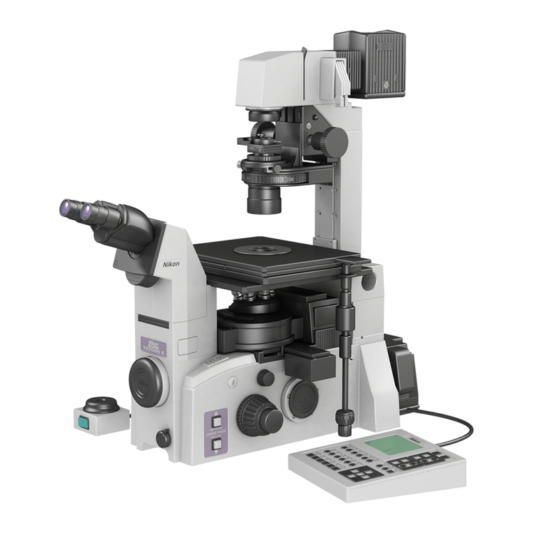
Nikon DIAPHOT 300 User manual

Ill
Instructions
NIKON
CORPORATION

Thank
you
for
your
purchase
of
Nikon’s
Inverted
Microscope
Diaphot
300.
Please
read
this
instruction
manual
thoroughly
in
order
to
become
acquainted
with
the
complete
system
and
its
operation.
We
hope
your
Diaphot
300
will
be
of
lasting
service.
Nikon
reserves
the
right
to
make
such
altera¬
tions
in
design
as
may
be
considered
necessary
in
the
light
of
experience.
For
this
reason,
particulars
and
illustrations
in
this
handbook
may
not
conform
in
every
detail
to
models
in
current
production.

Handling
Precautions
1.
Handle
Carefully!
Handle
the
microscope
gently,
taking
care
to
avoid
sharp
impacts.
2.
Purpose
Use
the
microscope
only
for
microscopic
observation.
Do
not
use
it
for
any
other
applications.
3.
Microscope
Location
Select
a
location
with
limited
exposure
to
dust,
vibration,
high
temperature
and
humidity
(40°C,
80%
or
more),
and
direct
sunlight.
Leave
a
certain
space
between
the
microscope
and
the
nearby
wall
to
allow
the
user
to
look
at
the
warning
labels
on
the
lamphouse.
4.
12V100W
Power
Supply
Unit
The
power
supply
unit
specified
on
page
53
"ELECTRICAL
SPECIFICATIONS"
is
the
power
supply
unit
to
light
up
the
Nikon
microscopes'
1
2V100W
lamp.
Do
not
use
it
for
other
purposes.
Also,
the
user
may
not
use
the
power
supply
unit
if
it
is
broken,
and
may
not
open
the
cover
of
the
power
supply
unit.
5.
Line
Voltage
Confirm
that
the
input
voltage
to
the
1
2V1
00W
power
supply
unit
corresponds
to
your
line
voltage.
Be
sure
to
use
the
specified
power
supply
unit
(described
in
page
53
"ELECTRICAL
SPECIFICATIONS").
6.
Light
Source
The
microscope
uses
a
1
2V,
1OOW
halogen
lamp
bulb
as
the
standard
light
source.
Do
not
use
any
lamp
not
described
in
the
"ELECTRICAL
SPECIFICATIONS"
(on
page
53).
If
a
lamp
bulb
of
over-rated
wattage
is
used,
the
light
adjusting
circuit
may
be
damaged.
7.
With
Lamp
On
—CAUTION
—
Do
not
touch
the
lamphouse
or
place
any
heat-sensitive
object
near
it,
since
the
lamphouse
becomes
extremely
hot
during
use.
Also
use
great
care
not
to
bring
volatile
substances
(such
as
gasoline,
thinner,
alcohol,
etc.)
close
to
the
lamphouse.
Such
exposure
may
result
in
inflammation
or
other
dangers.
8.
Replacing
the
Halogen
Lamp
Before
replacing
the
12V,
100W
halogen
lamp,
turn
off
the
power
switch
and
unplug
the
power
cord.
When
replacing
the
halogen
lamp,
wait
until
it
cools
down.
Do
not
touch
the
glass
of
the
halogen
lamp
with
bare
hands.

9.
Dirt
on
Lens
Do
not
leave
dust,
dirt
or
fingerprints
on
the
lens
or
lamp.
Dirt
or
stains
on
the
lens
or
mirror
will
deteriorate
image
quality.
10.
Focusing
Knobs
Never
attempt
to
turn
the
right-hand
and
left-hand
focusing
knob
in
opposite
directions
at
the
same
time
as
it
will
result
in
defects
or
damages.
An
attempt
to
turn
the
coarse
focusing
knob
further
after
it
reaches
its
limit
will
cause
defects
or
damages.
Never
turn
it
forcedly.

Care
and
Maintenance
1.
Lens
Cleaning
Dust
is
best
removed
with
a
soft
brush
or
gauze.
More
persistent
dirt,
such
as
fingerprints,
grease
and
oil,
may
be
removed
with
soft
cotton,
lens
tissue,
or
gauze
lightly
moistened
with
absolute
alcohol
(methyl
alcohol
or
ethyl
alcohol).
Use
only
xylene
to
clean
immersion
oil
off
objective
surfaces.
Do
not
use
xylene
to
clean
the
entrance
lens
at
the
bottom
of
the
eyepiece
tube
or
prism
surface
of
the
eyepiece
tube.
Absolute
alcohol
and
xylene
are
quite
inflammable.
Use
great
care
when
handling
them
and
when
setting
the
power
switch
on
and
off.
Be
very
careful
with
fire.
2.
Cleaning
Painted
Surfaces
Avoid
use
of
any
organic
solvents
(such
as
alcohol,
ether,
thinner,
etc.)
to
clean
the
painted
or
plastic
surfaces
of
the
instrument.
We
recommend
that
these
parts
be
cleaned
with
silicon
cloth.
3.
Never
Dismantle
Never
attempt
to
dismantle
the
instrument,
thereby
avoiding
the
possibility
of
impaired
operational
efficiency
and
accuracy.
4.
When
Not
In
Use
When
the
microscope
is
not
in
use,
cover
it
with
the
vinyl
cover,
and
store
it
in
a
dry
place
not
subject
to
mold.
We
especially
recommend
that
the
objectives
and
eyepieces
be
kept
in
a
container
(such
as
a
desiccator)
with
desiccant
in
it.
5.
Periodical
Inspection
To
maintain
the
performance
of
the
microscope,
we
recommend
you
to
check
the
microscope
periodically.
(For
details
of
inspection,
contact
your
dealer
or
nearest
Nikon
representative.)

I.
NOMENCLATURE
CONTENTS
Handling
Precautions
Care
and
Maintenance
I
.
NOMENCLATURE.
1
II.
BASIC
MICROSCOPY.
4
III.
PHOTOMICROGRAPHIC
PROCEDURE.
1
2
IV.
OPERATIONS
ON
COMPONENTS
.
16
1
.
ON/OFF
switching
of
power.
1
6
2.
Adjusting
Brightness.17
3.
Changing
Optical
Paths.19
4.
Filters.20
5.
Field
Aperture
Diaphragm
.
21
6.
Condenser
Aperture
Diaphragm
.
22
7.
System
Condenser
Turret
Unit
.
24
8.
Objectives.26
9.
Turret
Assembly.28
10.
Diopter
Adjustment.29
1
1
.
Adjusting
Interpupillary
Distance
.30
1
2.
Photomask.31
1
3.
Eyepiece
tube.32
14.
Focusing
Device.33
15.
Refocusing
Stopper
.
34
16.
Handling
Condenser
Flolder
.
35
17.
Tiltable
Illumination
Pillar.36
18.
Rectangular
Mechanical
Stage.38
19.
Photomicrography.39
V.
ASSEMBLY
.
4
2
VI.
SYSTEM
DIAGRAM
.
4
8
VII.
TROUBLESHOOTING
.
4
9
•
ELECTRICAL
SPECIFICATIONS
.
5
3
II.
BASIC
MICROSCOPY
III.
PHOTOMICROGRAPHIC
PROCEDURE
IV.
OPERATIONS
ON
COMPONENTS
V
ACCPMRIV
V
,
MOO
Cl
VIDL
I
VI.
SYSTEM
DIAGRAM
YU.
TROUBLESHOOTING
•
ELECTRICAL
SPECIFICATIONS

I.
NOMENCLATURE
1.
System
Components
(Right-hand)
Supplementary
lens
pocket
Field
aperture
diaphragm
lever
Figure
1-1

2.
System
Components
(Left-hand)
Condenser
refocusing
stopper
Condenser
mount
rotation
clamp
screw
Condenser
holder
Module
Condenser
turret
Annular
diaphragm
centering
screw
Condenser
lens
Objective
Revolving
nosepiece
Side
port
Coaxial
coarse/fine
focusing
knob
Refocusing
stopper
Light
intensity
control
dial
Condenser
mount
Condenser
centering
screw
System
condenser
turret
unit
Bertrand
lens
focusing
screw
Eyepiece
tube
port
Front
port
Figure
1
-2
2

3.
System
Components
(Rear)
Lamphouse
cable
connector
Figure
1-3
3

II.
BASIC
MICROSCOPY
For
the
normal
microscopy,
carry
out
steps
1
.
to
14.
For
phase
contrast
microscopy,
carry
out
steps
1
.
to
18.
For
detailed
operations,
see
Section
IV.
"OPERATIONS
ON
COMPONENTS
",
from
page
16.
If
the
microscope
has
not
been
assembled,
first
read
Section
V
.
"ASSEMBLY"
from
page
42.
1.
T
urn
on
the
power.
After
confirming
that
the
power
supply
is
set
for
the
correct
line
voltage,
turn
on
the
power
switch.
Set
the
light
intensity
control
dial
on
the
power
supply
unit
to
CTRL.
Figure
2-1
2.
S
et
the
lamp
voltage
to
6.
Rotate
the
light
intensity
control
dial
on
the
left
side
of
the
base
to
the
"6"
position.
(If
the
light
intensity
is
too
high
or
too
low,
adjust
it
properly.)
3.
S
et
the
optical
path
for
the
observation.
Set
the
turret
assembly
to
0.
(Eyepiece
tube
BT1
only.)
Set
the
optical
path
changeover
dial
on
the
right
side
of
the
base
to
A.
Figure
2-3

4.
S
elect
the
NCB11
filter.
Hold
the
nonslip
portion
of
the
filter
slider
to
push
in
the
NCB1
1
filter.
Do
not
touch
the
filter.
Keep
other
filters
out
of
the
optical
path.
For
phase
contrast
microscopy,
set
the
GIF
(green
interference)
filter,
instead
of
the
NCB1
1
filter,
in
the
optical
path.
Figure
2-4
5.
F
u
ll
y
open
the
field
aperture
and
condenser
aperture
diaphragms.
Raise
the
field
aperture
diaphragm
lever.
Turn
the
condenser
aperture
diaphragm
lever
to
the
right.
6.
A
djust
the
condenser
position.
Adjust
the
condenser
to
an
approximately
correct
position.
•
System
condenser
turret
unit
♦
LWD
condenser
Rotate
the
condenser
refocusing
stopper
by
half
turn
to
loosen
it,
and
rotate
the
condenser
focus
knob
to
lower
the
condenser
to
its
limit.
Rotate
the
turret
until
the
module
A
comes
to
the
front
(i.e.,
it
enters
the
optical
path).
♦
ELWD
condenser
Rotate
the
condenser
focus
knob
to
raise
the
condenser
to
the
upper
limit,
then
lower
the
condenser
by
approx.
1cm
from
the
limit.
Rotate
the
turret
until
the
module
A
comes
to
the
front
(i.e.,
it
enters
the
optical
path).
•
ELWD
condenser
Rotate
the
condenser
focus
knob
to
raise
the
condenser
to
the
upper
limit,
then
lower
the
condenser
by
approx.
2cm
from
the
limit.
•
SLWD
condenser
The
SLWD
condenser
requires
no
adjustment
since
it
is
fixed.

7.
M
o
ve
the
10
x
objective
into
the
optical
path.
Move
the
10x
objective
into
the
optical
path
by
rotating
the
revolving
nosepiece
securely
into
the
clickstop.
8.
A
djust
the
eyepiece
diopter.
Turn
down
the
reticle
in/out
lever
to
the
right
to
bring
the
photomask
into
the
optical
path.
Rotate
the
diopter
adjustment
ring
on
each
eyepiece
to
bring
the
photomask's
double
crosshairs
into
sharp
focus.
(Be
sure
to
perform
this
step
for
each
eye,
as
correct
focus
for
each
eye
is
usually
different.)
If
the
optional
rubber
eye
guards
are
used
and
if
you
wear
glasses,
fold
down
the
rubber
eyeguards.
9.
A
djust
the
interpupillary
distance.
Adjust
the
interpupillary
distance
until
the
viewfield
is
visible
as
a
single
image
through
both
eyepieces.
Figure
2-9

10.
Place
a
specimen
on
the
stage.
If
the
specimen
is
on
a
slide
glass,
be
sure
to
mount
it
with
its
cover
glass
facing
down.
(See
page
27.)
Move
the
stage
to
position
the
desired
section
of
the
specimen
into
the
viewfield.
Figure
2-10
1
1.
Focus.
Rotate
the
refocusing
stopper
on
the
left-hand
focusing
knob
counter¬
clockwise
to
unlock
the
stopper.
Rotate
the
coarse/fine
focusing
knob
to
focus
on
the
specimen.
NOTE:
Never
turn
the
left-hand
and
right-hand
knobs
in
the
opposite
directions
at
the
same
time,
as
damage
may
result.
12.
Center
the
condenser.
Narrow
down
the
field
aperture
diaphragm
until
the
diaphragm
edge
is
viewed
through
eyepieces.
Rotate
the
condenser
focus
knob
to
focus
the
image
of
the
field
aperture
diaphragm
on
the
specimen
surface.
Adjust
the
condenser
centering
screws
so
that
the
center
of
the
field
aperture
diaphragm
image
matches
the
center
of
the
viewfield.
NOTE:
If
the
SLWD
condenser
is
used,
this
centering
is
unnecessary.
(Fully
open
the
field
aperture
diaphragm.)
Figure
2-12
Figure
2-1
1
7

13.
Switch
to
the
40
x
objective
and
re-center
the
condenser.
Switch
to
the
40
x
objective.
Adjust
the
image
of
the
field
aperture
diaphragm
until
it
is
circumscribed
with
the
viewfield.
If
the
center
of
the
field
aperture
diaphragm
image
is
off
the
center
of
the
viewfield
(eccentric
condition),
readjust
with
the
condenser
centering
screws.
If
the
LWD
condenser
is
used,
tighten
the
condenser
refocusing
stopper.
14.
Perform
microscopy
with
a
desired
objective
♦
Switch
to
a
desired
objective.
♦
Focus
the
microscope.
♦
Adjust
the
field
aperture
diaphragm
until
it
is
inscribed
or
circumscribed
with
the
viewfield.
♦
Adjust
the
brightness
with
the
ND
filters
or
the
light
intensity
control
dial
on
the
base.
(Maintain
the
lamp
voltage
between
6
and
12.
For
color
photomicrography,
adjust
it
to
PHOTO.
See
page
17.)
♦
Stop
down
the
condenser
aperture
diaphragm
to
a
range
of
70
to
80%
of
the
objective's
numerical
aperture.
(See
page
22.)
♦
When
replacing
the
specimen,
you
can
use
the
refocusing
stopper
(page
34),
condenser
refocusing
stopper
(page
35),
and
pillar
tilting
mechanism
(page
36)
for
enhanced
efficiency.
Now,
the
basic
microscopic
operation
is
completed.
Improved
image
quality
may
be
achieved
by
slightly
opening
or
closing
the
condenser
aperture
diaphragm.
(See
page
22.)
For
phase
contrast
microscopy,
proceed
with
the
following
steps
15.
to
18.

Phase
Contrast
Microscopy
1
5.
Switch
to
the
phase
contrast
objective.
Rotate
the
revolving
nosepiece
to
bring
the
phase
contrast
objective
of
the
lowest
magnification
(ex.
4x)
into
the
optical
path.
Focus
the
microscope
with
the
coaxial
coarse/fine
focusing
knob.
(The
phase
contrast
objective
is
identified
as
it
is
impressed
with
the
Ph
code.
See
page
26.)
16.
Bring
the
phase
annular
diaphragm
into
the
optical
path.
Identify
the
annular
diaphragm
that
has
the
same
Ph
code
as
marked
on
the
objective
now
in
the
optical
path,
and
bring
it
into
the
optical
path.
(If
the
system
condenser
turret
unit
is
used,
rotate
the
turret
to
bring
the
module
having
the
same
Ph
code
as
marked
on
the
objective
into
the
optical
path.)
1
7.
Center
the
annular
diaphragm.
Open
the
field
aperture
diaphragm
to
the
full.
If
BT1
eyepiece
tube
is
used:
Set
the
turret
assembly
to
B.
While
observing
through
both
eyepieces,
rotate
the
Bertrand
lens
focusing
screw
to
focus
on
the
phase
plate
image
of
the
objective
and
the
annular
diaphragm
image
of
the
condenser.
If
BT2
eyepiece
is
used:
Remove
an
eyepiece
and
insert
the
centering
telescope
in
place.
Holding
the
knurled
part
of
the
centering
telelscope,
rotate
its
eyepiece
to
focus
on
both
the
phase
plate
image
of
the
objective
and
the
annular
diaphragm
image
of
the
condenser.
Figure
2-1
7

Adjust
so
that
the
phase
plate
image
is
concentric
with
the
annular
diaphragm
image.
Note
that
since
any
displacement
of
the
phase
plate
and
annular
images
will
cause
low
contrast
to
the
phase
contrast
image
of
the
specimen,the
exact
coincidence
of
the
two
images
is
necessary.
•
System
condenser
turret
unit
Open
the
condenser
aperture
diaphragm
to
the
full.
(The
optical
path
is
blocked
if
the
condenser
aperture
diaphragm
is
narrowed.)
Insert
two
hexagonal
screwdrivers
into
the
annular
diaphragm
centering
screws
of
the
module
in
the
optical
path,
and
rotate
the
screwdrivers
to
center
the
annular
diaphragm.
•
ELWD
condenser
Unclamp
the
right-hand
and
left-hand
turret
centering
knobs.
Rotate
the
centering
knobs
for
adjustment.
Through
PhL
centering,
other
annular
diaphragms
are
also
centered
automatically.
•
SLWD
condenser
Bring
the
PhL
annular
diaphragm
into
the
optical
path,
then
rotate
the
centering
screws
for
adjustment.
Maintain
the
field
aperture
diaphragm
fully
opened
during
observation.
(No
centering
adjustment
is
necessary
for
the
Phi
annular
diaphragm
since
it
is
fixed.)
Figure
2-19
Figure
2-20
10

18.
Perform
microscopy
with
a
desired
phase
contrast
objective.
•
Use
the
annular
diaphragm
(module)
that
has
the
same
Ph
code
as
marked
on
the
objective
on
the
optical
path.
Every
time
the
annular
diaphragm
(module)
is
changed,
center
the
annular
diaphragm
as
described
in
1
7
.
(As
for
the
ELWD
condenser,
once
centering
is
complete
with
PhL,
other
annular
diaphragms
are
also
centered
automatically.)
•
Adjust
the
field
aperture
diaphragm
until
it
is
circumscribed
with
the
viewfield.
(Open
it
to
the
full
for
the
SLWD
condenser)
•
Adjust
the
brightness
with
the
ND
filters
or
the
light
intensity
control
dial.
•
If
the
system
condenser
turret
unit
is
used,
always
open
the
condenser
aperture
diaphragm
to
the
full.
•
For
microscopy
at
the
maximum
contrast,
bring
the
GIF
filter
into
the
optical
path.
Keep
the
NCB1
1
filter
away
from
the
optical
path
when
using
GIF
filter.
•
When
replacing
the
specimen,
you
can
use
the
refocusing
stopper
(page
34),
condenser
refocusing
stopper
(page
35),
and
pillar
tilting
mechanism
(page
36)
for
enhanced
efficiency.
Now,
the
phase
contrast
microscopic
operation
is
all
completed.
When
you
observe
a
specimen
in
a
laboratory
dish
or
other
containers,
we
recommend
the
use
of
an
objective
that
has
a
correction
ring
for
compensating
the
thickness
of
the
dish
or
container
bottom.
(See
page
26.)

Ill
.
PHOTOMICROGRAPHIC
PROCEDURE
Nikon's
35mm
single-lens
reflex
cameras
(such
as
F-601)
and
photomicrographic
attachment
MICROFLEX
Series
(option)
may
be
used
for
photomicrography
with
the
Diaphot
300.
Mount
an
SLR
camera
directly
on
the
microscope
front
port.
Because
intermediate
magnification,
2.5x,
is
applied,
the
photomicrography
magnification
is
the
"magnification
of
the
objective
multiplied
by
2.5".
The
use
of
a
cable
release
(option)
eliminates
the
effects
of
vibration,
allowing
efficient
photomicrography.
Mount
a
photomicrographic
attachment
directly
on
the
side
port,
or
on
the
eyepiece
tube
port
via
the
optional
eyepiece
tube
bracket
and
the
trinocular
eyepiece
tube
for
the
upright
type
microscope
(option).
The
following
shows
the
photomicrographic
procedures
using
a
35
mm
SLR
camera.
Before
starting
photomicrography,
make
sure
that:
♦
The
microscope
is
ready
for
normal
microscopy.
(See
page
4.)
♦
The
camera
is
loaded
with
film.
(Refer
to
the
instruction
manual
that
comes
with
your
camera.)
♦
For
the
photomicrographic
procedures
using
the
photomicrographic
attachment,
refer
to
its
manual.
Rotate
the
optical
path
changeover
dial
to
align
the
optical
path
to
the
port
on
which
the
photomicrographic
attachment
is
mounted.
♦
Regarding
the
procedure
for
mounting
a
camera
or
photomicrographic
device,
see
Section
V
.
"ASSEMBLY",
from
page
42.
♦
For
detailed
operations
with
individual
components,
see
Section
IV
.
"OPERATIONS
ON
COMPONENTS
",
from
page
16.
1.
Turn
on
the
camera.
Flip
on
the
main
switch
of
the
camera.
Set
the
camera
for
the
appropriate
film
sensitivity,
exposure
mode,
and
photometry
mode.
(Refer
to
the
instructions
supplied
with
the
camera.)
Figure
3-1
2.
Adjust
lamp
voltage
to
PHOTO.
Set
the
light
intensity
control
dial
on
the
left
side
of
the
base
to
PHOTO,
(page
1
7)
(If
the
light
intensity
control
dial
on
the
power
supply
unit
is
used,
set
near
"9".)
Figure
3-2

3.
S
elect
the
optical
path
for
photomicrography.
Set
the
turret
assembly
to
0.
(This
applies
to
the
eyepiece
tube
BT1
only.)
Set
the
optical
path
changeover
dial
on
the
right
side
of
the
base
to
B.
4.
S
et
the
filters.
•
Daylight
type
color
film:
Bring
the
NCB1
1
filter
into
the
optical
path.
•
Monochrome
film
or
tungsten
type
color
film:
Bring
the
NCB1
1
filter
out
of
the
optical
path.
Figure
3-4
5.
C
ompose
the
frame.
Turn
down
the
reticle
in/out
lever
to
the
right
to
bring
the
photomask
into
the
optical
path.
Move
the
stage
to
bring
the
desired
object
inside
the
photomask,
(page
39)
6.
A
djust
the
focus.
While
observing
through
the
eyepieces,
focus
on
your
specimen
.
(page
40)
13

7.
A
djust
the
diaphragm.
Narrow
the
field
aperture
diaphragm
until
it
is
slightly
wider
than
the
area
to
be
photomicrographed.
Adjust
contrast,
depth
of
focus
and
resolution
with
the
condenser
aperture
diaphragm.
(This
diaphragm
should
usually
be
set
to
a
range
of
70
to
80%
of
the
objective's
numerical
aperture.
See
page
22
.
)
Figure
3-7
8.
C
h
e
ck
the
exposure
time.
Check
the
exposure
time
displayed
on
the
camera.
Adjust
the
brightness
so
that
the
exposure
time
is
longer
than
1
/8
of
a
second.
•
Color
film:
Adjust
with
the
ND
filters.
(Keep
the
NCB1
1
filter
in
the
optical
path.)
•
Monochrome
film:
Adjust
with
the
ND
filters
or
by
varying
the
lamp
voltage.
Figure
3-8
9.
P
r
event
external
light
from
coming
in.
Fit
the
finder
cap
(option)
to
the
camera
finder.
(Keep
the
finder
cap
on
the
finder
except
when
the
exposure
time
should
be
checked
through
the
finder.)
Set
the
turret
assembly
to
C.
(This
applies
to
the
eyepiece
tube
BT1
,
especially
for
long-time
exposure.)
Figure
3-9
14
Table of contents
Other Nikon Microscope manuals

Nikon
Nikon E800 User manual

Nikon
Nikon Alphaphot User manual

Nikon
Nikon eclipse E200 User manual

Nikon
Nikon Live Cell 2 User manual

Nikon
Nikon SMZ-1 User manual
Nikon
Nikon ECLIPSE Ei User manual

Nikon
Nikon ECLIPSE 80i User manual

Nikon
Nikon Eclipse Ti TIFT 1454 User manual

Nikon
Nikon ECLIPSE E200 POL User manual

Nikon
Nikon Eclipse E400 User manual

Nikon
Nikon Eclipse TS100 User manual

Nikon
Nikon A1R Series Service manual

Nikon
Nikon eclipse Ci-S User manual

Nikon
Nikon N-STORM User manual

Nikon
Nikon SMZ-1 User manual

Nikon
Nikon ECLIPSE Si User manual
Nikon
Nikon LABOPHOT2-POL User manual

Nikon
Nikon Eclipse E400 User manual

Nikon
Nikon SMZ25 User manual
Nikon
Nikon Multizoom AZ100 User manual