Nine Eagles GALAXY VISITOR 3 User manual
Operating Instructions
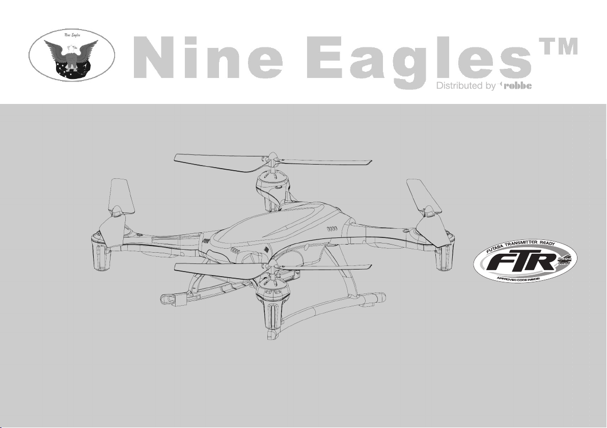
GALAXY VISITOR 3
RTF FTR 2.4 GHz
No. NE2529M2
No. NE2529M1
with
still photo and video function
and height stabilisation!
V01/05/14
Operating Instructions - GALAXY VISITOR 3 RTF FTR 2.4 GHz No. NE2529M2
No. NE2529M1
2
FUTABA Transmitter Ready, abbreviated to FTR, applies to selected models from the Nine Eagles
range. These models' transmitter and receiver work with the FUTABA S-FHSS code, which means that
they can also be controlled by FUTABA transmitters which can be operated in S-FHSS mode.
If you wish to use a radio control transmitter other than the original one, please note that those func-
tions which are selected using the AUX buttons will not be available (mode selection, Auto-Return
function and intelligent flight mode). The photo / video function can be assigned to rotary buttons and
/ or sliders; the method of programming is described on pages 22 / 23.

Explanation of specialist terms:
Climb and descent ("Collective pitch / throttle"):
this controls the model's climb and descent.
Yaw: The model's movement around the vertical axis.
The model's nose turns to right or left.
Pitch-axis: The model's movement around the lateral
axis: forward or reverse flight.
Roll: The model's movement around the longitudinal
axis: sideways movement to right or left.
Dual Rate: Switchable travel reduction for control mo-
vements.
Binding:
Creating the radio link between transmitter
and receiver.
3
Contents Page
Explanation: FTR system 2
Explanation of specialist terms / Contents 3
Special features of the GALAXY VISITOR 3 4
Model description 4
Safety Notes 5, 6
Set contents / Specification 7
Transmitter layout / overview - GALAXY VISITOR 3 8, 9
Primary and expanded control function settings 10
Charging the flight battery 10
Safety Notes regarding LiPo batteries 11
Flight preparations 12
Trim adjustments 13
Basic information on flying the GALAXY VISITOR 3 14
Practice flying 15
Brake function 15
Signal Loss Protection function 16
Conventional flight mode and intelligent flight mode 16
Switching the acceleration sensor on and off 17
Meaning of and selecting the 3 throttle modes 17
"Auto-Return" function 18
Binding the transmitter and receiver 19
Calibrating the acceleration sensor 20
Dual-Rate function 21
Speed of the Auto-Return function 21
Transmitter magnet sensor 22
Camera 22, 23
After repairs 23
Replacement Parts list 24, 25
Conformity Declaration 26
Please be sure to observe the safety notes
regarding the safe handling of Lithium-
Ion-Polymer batteries on page 11.
Operating Instructions - GALAXY VISITOR 3 RTF FTR 2.4 GHz No. NE2529M2
No. NE2529M1

Special features of the GALAXY VISITOR 3 RTF FTR
Two flight modes and three throttle modes are available:
Flight mode:
• Conventional flying and intelligent flying.
Throttle mode:
Beginner mode, height stabilisation mode and normal mode.
• A push-button on the transmitter provides a simple means of tog-
gling between the flight modes.
• The "Headless Flight Mode" in intelligent flight mode makes it
particularly easy for beginners to master the quadrocopter.
• An "Auto-Return" function ensures that the quadrocopter comes
straight back to the pilot.
• Brake function. The copter slows down automatically when the
pilot releases the sticks.
Key features:
• Anti-collision guard simply by switching the acceleration sensor
on and off.
• LEDs of different colour make it simple to detect the model's atti-
tude.
• On-board micro digital camera for video and still pictures.
• Integral height sensor.
• Signal Loss Protection function: if the signal is lost, the copter
automatically hovers and lands.
4
Model description
The GALAXY VISITOR 3 is a 2.4 GHz mini-quadrocopter of the
latest generation.
The highly developed nine-axis gyro and stabilisation system is the
key to the model's extremely simple method of control and accurate
response. The GALAXY VISITOR 3's simple control system and
good inherent stability make it an excellent choice for the beginner.
This quadrocopter's agility level is user-variable, and this ensures
that flying the GALAXY VISITOR 3 is never boring even for ad-
vanced pilots. The model can also cope well with gentle breezes
when flown outdoors. The GALAXY VISITOR 3 combines many
advantages in one model, including small size, low weight and safe
operation.
Operating Instructions - GALAXY VISITOR 3 RTF FTR 2.4 GHz No. NE2529M2
No. NE2529M1
Be sure to read these Safety Notes before you assemble
your model. Always keep to the procedures and settings re-
commended in the instructions.
If you are operating a radio-controlled model aircraft, heli-
copter, car or boat for the first time, we recommend that you
enlist an experienced modeller to help you.
Safety Notes
Radio-controlled models are not toys in the usual sense of the term.
Young persons under eighteen years should only be allowed to ope-
rate them under the supervision of an adult.
Building and operating these models requires technical expertise,
manual skills, a careful attitude and safety-conscious behaviour.
Errors, negligence and omissions in building or flying these models
can result in serious personal injury and damage to property.
Since the manufacturer and vendor are not in a position to check
that your models are built and operated correctly, all we can do is
bring these hazards expressly to your attention. We deny all further
liability.
Helicopter rotors, and all moving parts generally,
constitute a constant injury hazard. It is essential to
avoid touching such parts.
Please bear in mind that motors and speed control-
lers may become hot when operating. It is essential
to avoid touching such parts.
Do not stand close to the hazard area around rotating
parts when an electric motor is connected to the flight
battery.
You must also take care to keep all other objects away
from moving or rotating parts.
Observe the instructions provided by the battery ma-
nufacturer.
Overcharged or incorrectly charged batteries may explo-
de. Take care to maintain correct polarity.
Notes on the use of dry cells:
Do not attempt to recharge dry cells, do not open them,
and do not incinerate them. Remove exhausted dry cells
from the transmitter after use. Escaped electrolyte may
ruin the transmitter.
Ensure the equipment is protected from dust, dirt and moisture
contamination. Do not subject the system to excessive heat, cold
or vibration.
Use the recommended charger only, and charge the batteries only
for the prescribed period.
Check your equipment for damage at regular intervals, and re-
place defective components with genuine spare parts.
Do not re-use any devices which have been damaged in a crash or
by water, even when they have dried out again.
Send the equipment to the robbe Service Department for che-
cking, or replace the parts in question.
5
Operating Instructions - GALAXY VISITOR 3 RTF FTR 2.4 GHz No. NE2529M2
No. NE2529M1

Crash or water damage can result in concealed defects which may
lead to failure in subsequent use.
Use only those components and accessories which we specifi-
cally recommend.
Do not carry out modifications to the radio control system compo-
nents apart from those described in the instructions.
Operating the model
Caution - injury hazard:
Please keep a safe distance away from your model air-
craft. Never fly over spectators, other pilots or yourself.
Always fly manoeuvres facing away from other pilots and
spectators.
• Never y close to high-tension overhead cables or residential
areas.
• Do not operate your model in the vicinity of canal locks or open
waterways.
• Do not operate your model from public roads, motorways,
paths and squares etc.; use authorised model flying sites only.
•Neveroperatethemodelinstormyweather.
Insurance
Ground-based models are usually covered by standard personal
third-party insurance policies. In order to fly model aircraft you
will need to extend the cover of your existing policy, or take out
specific insurance.
Check your insurance policy and take out new cover if ne-
cessary.
Liability exclusion:
robbe Modellsport is unable to ensure that you observe the as-
sembly and operating instructions, or the conditions and methods
used for installing, operating and maintaining the model compo-
nents.
For this reason we accept no liability for loss, damage or costs
which are due to the erroneous use and operation of our pro-
ducts, or are connected with such operation in any way.
Regardless of the legal argument employed, our obligation to
pay compensation is limited to the invoice value of those robbe
products directly involved in the event in which the damage oc-
curred, unless otherwise prescribed by law. This does not apply
if the company is deemed to have unlimited liability according to
statutory regulation due to deliberate or gross negligence.
6
Operating Instructions - GALAXY VISITOR 3 RTF FTR 2.4 GHz No. NE2529M2
No. NE2529M1

Dear customer,
Congratulations on choosing a factory-assembled mo-
del quadrocopter with video and photo function and
height stabilisation from our range. Many thanks for
placing your trust in us.
The model can be completed and prepared for flight
very quickly. Please read right through these instruc-
tions before attempting to fly the model for the first
time, as this will make it much easier to operate the
model safely.
All directions, such as “right-hand”, are as seen from
the tail of the model, looking forward.
Specification:
Main rotor ∅: approx. 147 mm
Length: approx. 163 mm
Width: approx. 163 mm
Height: approx. 78 mm
Flight battery: 3.7 V / 1200 mAh LiPo
All-up weight: approx. 135 g
RC functions:
Pitch-axis, roll, yaw, climb / descent
Video and still photo function
Set contents:
1 x High-end mini-quadrocopter, factory-assembled and set up, ready to fly
1 x LiPo battery, 3.7 V / 1200 mAh with polarised connector
1 x 230 V battery charger
1 x 2.4 GHz four-channel transmitter set to Mode 2 (NE2529M2)
Mode 1 (NE2529M1) (stick mode cannot be changed)
4 x AA-size dry cells
1 x Four replacement rotors
1 x Screwdriver
1 x Comprehensive operating and flying instructions
1 x Camera set with SD card and card reader
Camera resolution 1280 x 720 pixels HD
7
Operating Instructions - GALAXY VISITOR 3 RTF FTR 2.4 GHz No. NE2529M2
No. NE2529M1

8
Transmitter channel assignment, Mode 2:
Yaw
trim Roll
trim
Roll and pitch-axis controls
Dual-Rate settings
Throttle and
yaw control
Pitch-axis trimThrottle trim
Dual-Rate status indicator
Yaw trim display Roll trim display
Status indicator
Transmitter battery
Throttle status indicator
Pitch-axis trim display
Throttle trim
Indicator
Screen
Operating Instructions - GALAXY VISITOR 3 RTF FTR 2.4 GHz No. NE2529M2
No. NE2529M1
Transmitter channel assignment, Mode 1:
Yaw
trim Roll
trim
Pitch-axis and
yaw control
Throttle
and roll control
Dual-Rate settings
Throttle trimPitch-axis trim
Dual-Rate status indicator
Yaw trim display Roll trim display
Status indicator
Transmitter battery
Throttle status indicator
Throttle trim display
Pitch-axis trim display
Screen

9
Overview - GALAXY VISITOR 3
Red
navigation
LED
White
navigation
LED
Red
navigation
LED
Camera
Battery
compartment
Operating Instructions - GALAXY VISITOR 3 RTF FTR 2.4 GHz No. NE2529M2
No. NE2529M1
"AUX 2" push-switch:
Throttle mode select
switch
"AUX 1" push-switch:
Flight mode select switch
"VIDEO" push-switch:
Starts and stops video recording
"PICTURE" push-switch:
shutter release button
Battery compartment
cover
Transmitter back panel:
White
navigation
LED
Red status LED
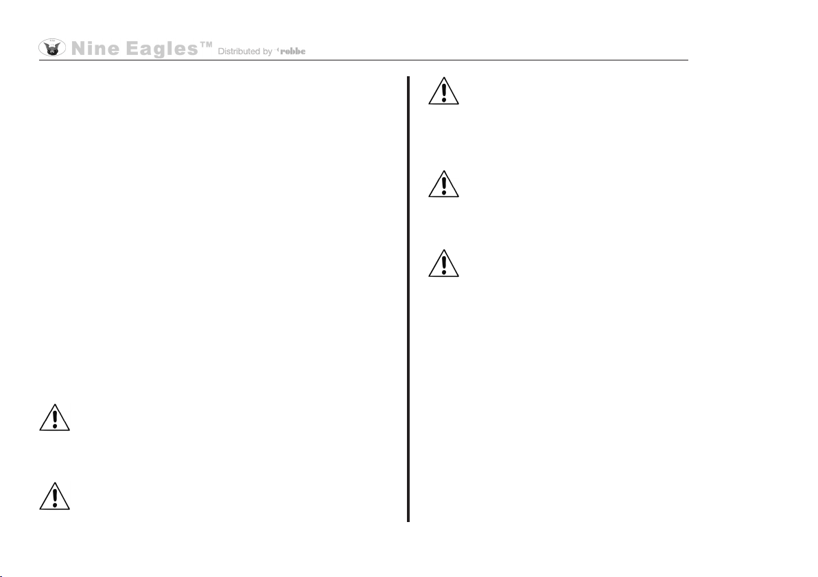
"Primary" and "expanded" control function setting
The transmitter offers the facility to adjust the sensitivity of the
stick movements. Initially we recommend "softer" reduced travels
for beginners.
Open the transmitter battery compartment and insert the four AA
cells* (check for correct polarity).
Procedure:
Switch the transmitter on, and press
the right-hand stick inward.
Reduced control function
The "Dual-Rate status indicator" disc
on the screen is reduced to half.
Manoeuvrability 50%
Expanded control function:
Press the right-hand stick inward
again.
The full black disc now appears on the
screen.
Manoeuvrability 100%
* Please read the information regarding dry cells on page 5.
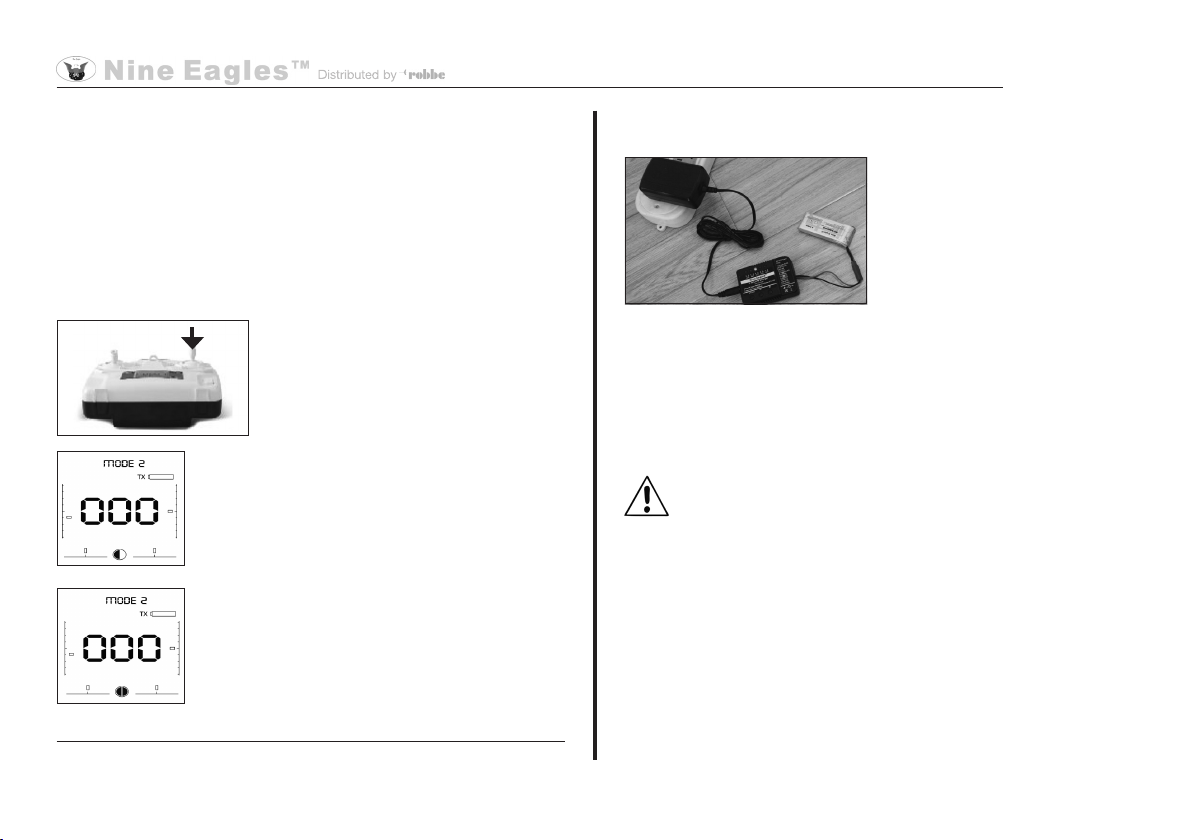
Charging the flight battery
Connect the battery charger to
the mains PSU, and plug the
PSU into a mains socket. The
red monitor LED on the charger
lights up.
Connect the battery to the char-
ger, and use "+" or "-" to set the
charge current (high = fast, low = longer battery life). Press the
Start button. The monitor LED flashes. When the charge process
is finished, all the LEDs on the charger flash, and you will hear
an audible beep. Disconnect the battery from the charger, then
disconnect the mains PSU from the wall socket.
Safety Notes
The battery must not be left unsupervised during the
charge process or be placed on an inflammable surface.
Protect from damp. Do not subject it to direct sunshine,
and do not cover the charger.
Do not charge batteries that are hot to the touch. Allow
batteries to cool down to ambient temperature. Charge
the battery only using the charger included in the set; do
not use any other charger. The charger should only be
used to charge the battery included in the set. Not suitable
for charging the transmitter battery!
It is essential to read right through the safety notes
relating to LiPo batteries on page 11.
10
Operating Instructions - GALAXY VISITOR 3 RTF FTR 2.4 GHz No. NE2529M2
No. NE2529M1
11
LIABILITY EXCLUSION
Since robbe Modellsport is not in a position to monitor the handling of these batteries, we expressly deny all liability and guarantee
claims where the batteries have been incorrectly charged, discharged or handled.
Safety Notes regarding LiPo batteries:
• Do not place the battery in water or any other liquid.
• Never heat or incinerate the pack, or place it in a microwave oven.
• Avoid short-circuits, and never charge the battery with reversed polarity.
• Do not subject the battery to pressure or shock loads, and never distort or throw the pack.
• Never solder directly to the battery.
• Do not modify or open the battery.
• Batteries must only be charged with a suitable charger; never connect the battery directly to a mains power supply.
• Never charge or discharge a battery in bright sunlight, or close to a heater or open re.
• Do not use the battery in areas subject to high levels of static electricity.
• Never leave the battery on charge unsupervised.
• Do not charge the battery in an inammable environment, or on an inammable surface.
• Any of these errors can result in damage to the battery, explosion or re.
• Keep the battery away from children.
• If electrolyte should escape, do not expose it to re, as the material is highly inammable and may ignite.
• Do not allow uid electrolyte to come into contact with eyes. If this should happen, ush with copious amounts of water and
contact a doctor without delay.
• The uid electrolyte can also be removed from clothing and other objects by rinsing with copious amounts of water.
Operating Instructions - GALAXY VISITOR 3 RTF FTR 2.4 GHz No. NE2529M2
No. NE2529M1

12
Flight preparation
Visual checks
Before flying the model, check that there is no obvious damage
to the case or rotors.
1. Open the transmitter battery
compartment and insert the four
AA dry cells (maintain correct
polarity). Lay the transmitter
down flat, and switch it on. Do
not touch the transmitter for at
least three seconds!
2. Place the flight battery in the Galaxy Visitor 3 and connect it.
Now leave the Galaxy Visitor 3 motionless until the red status
LED lights up constantly. This may take a little while.
3. At lift-off the transmit-
ter aerial must point
towards the red status
LED on the Galaxy Visi-
tor 3.
Operating Instructions - GALAXY VISITOR 3 RTF FTR 2.4 GHz No. NE2529M2
No. NE2529M1
4. If you wish to fly the Galaxy Visitor 3 in intelligent control mode,
the transmitter aerial must be directed at the model constantly!
5. The Galaxy Visitor 3 must not be taken off until the red sta-
tus LED lights up constantly in conventional control mode, or
flashes red in intelligent control mode.
After every landing the Galaxy Visitor 3 carries out a brief in-
itialisation procedure; please ensure that the status LED indi-
cates the same mode as previously. If this is not the case, dis-
connect the flight battery then re-connect it so that the model
can re-initialise itself.
Never take off if the red status LED is not glowing
constantly or flashing!
6. If you intend to fly outdoors at a height of more than three me-
tres using "normal" throttle and "height stabilisation" modes,
there is a method of reducing the model's altitude quickly: all
you have to do is press the AUX2 button once in normal mode,
or twice in height stabilisation mode. This takes you to Begin-
ner mode, and the copter automatically descends to a height
of about 2 - 3 metres. After pressing the AUX2 button, we re-
commend that you keep a careful watch on the model's height,
and adjust it with the throttle stick if necessary.
7. When the red LED starts flashing at a high rate, the battery
has almost reached the end of its capacity. At this point you
should land the copter as quickly as possible.
13
Operating Instructions - GALAXY VISITOR 3 RTF FTR 2.4 GHz No. NE2529M2
No. NE2529M1
Trim settings, Mode 1
Throttle trim:
If the rotors start to spin without the
throttle stick being touched, or do not
respond to stick movements, you must
adjust the throttle trim until they stop
moving.
Yaw trim:
If the model's nose turns to right or left
when it lifts off, adjust the yaw trim to
correct the rotation until the model
maintains a stable heading.
Pitch-axis trim:
If the model flies forward or back when
it lifts off, adjust the pitch-axis trim until
it hovers over one point.
Roll trim:
If the model moves bodily to left or right
when it lifts off, adjust the roll trim until
the model remains in a stable hover.
Trim settings, Mode 2
Throttle trim:
If the rotors start to spin without the
throttle stick being touched, or do not
respond to stick movements, you must
adjust the throttle trim until they stop
moving.
Yaw trim:
If the model's nose turns to right or left
when it lifts off, adjust the yaw trim to
correct the rotation until the model
maintains a stable heading.
Pitch-axis trim:
If the model flies forward or back when
it lifts off, adjust the pitch-axis trim until
it hovers over one point.
Roll trim:
If the model moves bodily to left or right
when it lifts off, adjust the roll trim until
the model remains in a stable hover.

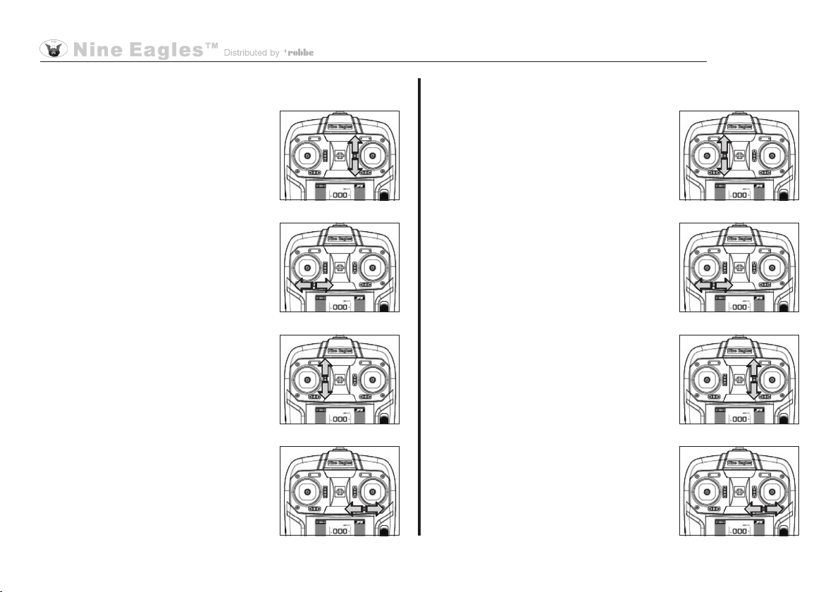
Basic information on flying the GALAXY VISITOR 3
Mode 1 Mode 2
Move the throttle stick for-
ward, and the GALAXY
VISITOR 3 climbs. Pull it
back, and the model de-
scends.
Move the yaw stick to
one side, and the GALA-
XY VISITOR 3 rotates in
the corresponding direc-
tion around the vertical
axis.
If you move the pitch-axis
stick forward or back, the
GALAXY VISITOR 3 flies
in the corresponding di-
rection.
If you move the roll stick
to right or left, the GALA-
XY VISITOR 3 moves in
the corresponding direc-
tion.
14
CAUTION: only the third illustra-
tion shows the model facing left.
All the other pictures show the
model's tail facing the observer.
Please note that the direction of
control response changes accor-
ding to the model's flight attitude.
For example, the pitch-axis and
roll functions are reversed when
the model is flying toward the pi-
lot.
CAUTION: since magnetic field
sensors are fitted to the model as
well as the transmitter, the qua-
drocopter should not be operated
in the vicinity of powerful magne-
tic fields, such as high-tension
overhead cables or transformers.
The model could crash if interfe-
rence affects the magnetic sen-
sors.
Operating Instructions - GALAXY VISITOR 3 RTF FTR 2.4 GHz No. NE2529M2
No. NE2529M1
a
N
N
front rear
15
Once you have learned the knack of taking off briskly, maintai-
ning a given height, and landing softly, it is time to practise the
roll, pitch-axis and yaw functions. During these flights keep the
tail facing you at all times.
It is important to keep your model in one position at first; try to
keep it in the same position and attitude as after take-off.
CAUTION: land the model immediately when the flight bat-
tery is almost flat. For example: when the GALAXY VISI-
TOR 3 cannot climb higher than 0.5 metres. Don't fly the
model again until you have given the flight battery a full
charge.
Remove the flight battery from the model immediately after lan-
ding, and switch the transmitter off.
If your model crashes after colliding with an obstacle, it is es-
sential to check for damage caused by the impact before you fly
again.
Please don't leave the flight battery in the model when you are
not actually flying it. Never discharge the battery completely, as
deep-discharging can ruin it. If you do not intend to fly the model
for a long period, it is best to remove the dry cells from the trans-
mitter too.
Brake function
The GALAXY VISITOR 3 features an automatic brake function.
If you abruptly release the roll / pitch-axis stick while the model
is flying forward, its forward speed is automatically reduced. This
function can be very useful in avoiding collisions with obstacles.
Practice flying
The flying field
The model should only ever be flown in a suitable environment
such as an indoor flying hall, devoid of obstacles. If you wish to
fly the quadrocopter in the open air, please note that there should
be no wind, and no trees, high-tension cables or other obstacles
in the vicinity.
Practising with the model
Check the model and the radio control system, then switch
the transmitter on, followed by the model.
Place the GALAXY VISITOR 3 on the ground about two metres
in front of you, and check that its tail is facing you.
Cautiously move the throttle stick forward until the model lifts off.
Allow the copter to rise briskly to a height of about 0.5 metres,
and try to keep it motionless. If the model is unstable, uncon-
trollable or vibrates, reduce the throttle again immediately and
land the GALAXY VISITOR 3.
If you are a beginner, we recommend that you keep to a height
of about 0.5 metres during the first few flights. Please do not fly
lower than 0.3 metres, because the model will then be in ground-
effect, which is caused by the downflow of air from the rotors.
This effect makes it more difficult to fly the machine smoothly. It
is also important not to fly too high, as any unintended crash will
then result in more serious damage.
Operating Instructions - GALAXY VISITOR 3 RTF FTR 2.4 GHz No. NE2529M2
No. NE2529M1
16
Signal Loss Protection function
If the radio link is interrupted while the model is in the air - e.g. the
copter flies beyond the range of the radio control system, the trans-
mitter fails, interference affects the signal, etc. - the model takes up
a stable hover at a height of about 2 - 3 m for about five seconds
before descending automatically to a landing.
Conventional flight mode and intelligent flight mode
Until now the direction of flight of radio-controlled models was
always fixed, i.e. forward was always forward, and back was al-
ways back. The drawback to a fixed direction of flight is that the
pilot has to re-think his commands when, for example, the model
is flying towards him. In this case the pilot gives a command to
turn right or left, but the model now moves in exactly the opposite
direction relative to him. This "conventional flight mode" is very
difficult to master, especially for the beginner. The situation is
even worse with quadrocopters, as their layout makes it even
harder to detect which side of the model is forward, back, right
and left. That is why we have incorporated an "intelligent control
mode" in the GALAXY VISITOR 3. If the machine is operated in
this control mode, forward on the model does not always equate
to the forward direction of flight. This means that the model al-
ways flies towards the pilot if he moves the pitch-axis stick toward
himself. It makes no difference where the actual front face of the
quadrocopter is pointing.
CAUTION: when you operate the copter in intelligent flight mode,
the transmitter aerial should always face the model, as this flight
mode works best in this situation.
Switching between the two flight modes
First switch the radio control transmitter on, then connect the re-
ceiver power supply in the GALAXY VISITOR 3. Hold the AUX 1
button pressed in for about three seconds, and do not release it
until the Status LED starts flashing slowly. This method can be
used at any time to switch between the two flight modes. If you
are a beginner, we recommend that you set the mode on the
ground, and do not change it in flight, otherwise you could lose
control of the model.
Conventional flight mode
The Status LED glows constantly red when the GALAXY VISI-
TOR 3 is operated in conventional flight mode. In this mode "for-
ward on the model" is always "the forward flight direction".
Intelligent flight mode
The Status LED flashes slowly red when the GALAXY VISITOR 3 is
operated in intelligent flight mode. In this mode "forward on the mo-
del" is always the side which faces away from the transmitter.
CAUTION: when the model takes off, the transmitter aerial
must always face the Status LED. If you neglect this, you
may find that the control directions are not correct.
Operating Instructions - GALAXY VISITOR 3 RTF FTR 2.4 GHz No. NE2529M2
No. NE2529M1

3. Normal mode: in this mode the model responds to control
commands like a normal quadrocopter.
The factory default setting is "beginner mode active".
To select any of the modes, simply press the AUX2 button once.
The new mode is indicated by the following flashing sequences:
Switch to beginner mode: the Status LED goes out, flashes
once quickly, then glows constantly.
Switch to height stabilisation mode: the Status LED goes out,
flashes twice quickly, then glows constantly.
Switch to normal mode: the Status LED goes out, flashes three
times quickly, then glows constantly.
Mode switching occurs in a loop in the following sequence:
Beginner mode Height stabilisation mode Normal
mode Beginner mode, etc.
Caution: we recommend that you only switch throttle
modes while in conventional flight mode. If you carry out
the switch in intelligent flight mode, the flashing Status LED
makes it much more difficult to count the flashing signals
which indicate the mode to which you have switched.
If you switch from normal to height stabilisation mode, the throttle
value is reset. If the throttle stick is then not in the centre, the
model could descend rapidly or even crash. We therefore recom-
mend switching the throttle mode before take-off.
Switching the acceleration sensor on and off
When you are confident of flying the GALAXY VISITOR 3, you
may wish to switch off the acceleration sensors in order to ma-
ke the model more agile. This is accomplished by moving the
throttle stick fully back in mode 2, then moving the right-hand
stick to the bottom left corner. Hold it in this position until the Sta-
tus LED goes out. Now release the stick: the acceleration sensor
is switched off.
Repeat the procedure to switch the sensor on again. The only dif-
ference is that the Status LED glows constantly when the sensor
is switched on.
CAUTION: in the GALAXY VISITOR 3's default condition (as sup-
plied) the acceleration sensors are switched on.
Tip: if you are not sure whether the acceleration sensor is swit-
ched on or off, you can tell by the Status LED of the GALAXY
VISITOR 3.
Meaning of and selecting the three throttle modes
1. Beginner mode: in this mode the model's maximum flying
height is limited: even at the full-throttle position the model will
fly no higher than 2 - 3 metres. If you move the throttle stick
back again, the model responds by descending. This mode
is intended to make it easier for the beginner to control the
copter, to avoid crashes and collisions.
2. Height stabilisation mode: in this mode, if you quickly move
the throttle stick to centre from its current position, the cur-
rent throttle value is stored, and the model maintains constant
height in the hover.
17
Operating Instructions - GALAXY VISITOR 3 RTF FTR 2.4 GHz No. NE2529M2
No. NE2529M1
18
Operating Instructions - GALAXY VISITOR 3 RTF FTR 2.4 GHz No. NE2529M2
No. NE2529M1
How is the Auto-Return function stopped?
Method 1:
The Auto-Return function ceases immediately if you operate any
of the controls other than throttle.
Method 2:
Briefly press the AUX 1 button a second time.
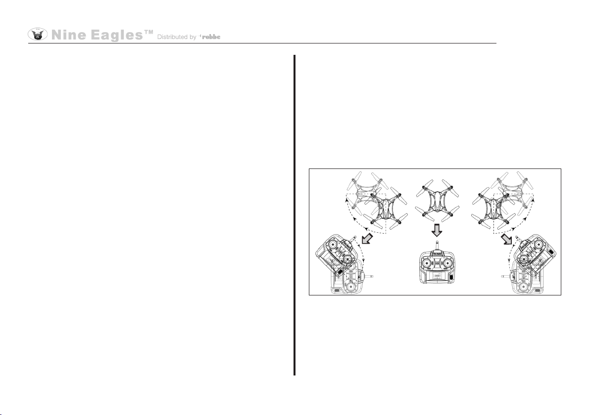
Flight directions while Auto-Return is in use
The model always flies towards the transmitter aerial when the
Auto-Return function is in use. Please refer to the illustration below.
The direction of flight in Auto-Return mode changes if the positi-
on of the transmitter is altered.
Changing the direction of flight when the Auto-Return func-
tion is in use
While the model is in Auto-Return mode, you can influence its
direction of flight by changing the position of the transmitter. For
"Auto-Return" function
What is the Auto-Return function?
The effect of the Auto-Return function is to cause the model to
return to the pilot automatically and immediately, regardless of its
attitude. Simply press the AUX 1 button on the transmitter to trig-
ger the Auto-Return function. It makes no difference which flight
mode is currently selected.
When is it sensible to use this function?
This function makes sense in any situation where you can no
longer clearly detect the GV 3's flight attitude. For example, if
you allow the model to fly too far away. Simply press the AUX 1
button: the red Status LED flashes at a high rate, and the GV 3
immediately starts flying back to you.
Notes on using the Auto-Return function
When you are using this function, you should still use the throttle
stick to maintain the model at a steady height. All the other con-
trols must be left untouched while the Auto-Return function is in
use. If you give another control command, the Auto-Return func-
tion ceases immediately.
The transmitter must continue to point at the model while the
function is in use, and there should be no obstacles in the way.
If the model flies past you, turn round and point the transmitter
aerial at the GALAXY VISITOR 3 again. If not, the model will
simply maintain its course.
The Auto-Return function should only be used indoors in a hall of
adequate size, or at a suitable flying field.
19
Operating Instructions - GALAXY VISITOR 3 RTF FTR 2.4 GHz No. NE2529M2
No. NE2529M1
example, you can fly the model in a circle around you. With the
GALAXY VISITOR 3 in Auto Return mode, simply point the trans-
mitter aerial at the copter and turn round. Since the model always
tries to fly towards the aerial, the result is a circular flight path.
You can also cause the model to turn left or right: simply turn the
transmitter in the opposite direction to the desired turn. For exam-
ple, if you wish the GALAXY VISITOR 3 to move to the right, turn
the transmitter (and therefore its aerial) to the left, and vice versa.
NOTE: the Auto-Return function is available both in conventional
and intelligent flight mode.
Binding the transmitter and receiver
Switch the transmitter on, set the throttle stick to the bottom posi-
tion (Idle), and place it about 30 cm from the model.
Switch the copter on by connecting the flight battery, and leave it
motionless. The red LED now flashes to indicate that the model
is in Bind mode. The binding procedure is successful if the red
LED glows constantly.
Binding is only necessary if you replace one of the radio control
system components.
CAUTION: during the take-off procedure the transmitter
aerial must point towards the model's red LED. If you igno-
re this, you may encounter problems in flight when the in-
telligent flight mode or the Auto-Return function is selected.

Quitting calibration mode
Press the left-hand transmitter stick on-
ce. When you hear a further beep, you
have left the mode, and can fly the mo-
del.
Note:
If calibration mode does not immediately start correctly, repeat
the procedure until the Status LED flashes. Please be careful not
to hold the right-hand stick pressed in for too long, otherwise you
will enter Dual Rate set-up mode.
20
Calibrating the acceleration sensor
The acceleration sensor can be adjusted at the model's receiver.
Normally the machine is calibrated correctly at the factory, and
is immediately ready to fly. If you notice inconsistencies in the
model's behaviour in flight, you can re-calibrate the acceleration
sensor and thereby improve its flying characteristics.
Entering calibration mode
First switch the transmitter on, then
place the model in a horizontal position
and connect the flight battery. Hold the
right-hand transmitter stick pressed in,
then press the left-hand stick three times
in sequence. You will hear a beep which
indicates that you are in Calibration mo-
de. Release the right-hand stick again.
Calibration
Move the throttle trim on the transmitter
upward. The Status LED now flashes
slowly, and the acceleration sensor is in
calibration mode. Now switch the trans-
mitter off and immediately on again. The
procedure is complete when the Status
LED glows constantly.
Operating Instructions - GALAXY VISITOR 3 RTF FTR 2.4 GHz No. NE2529M2
No. NE2529M1
Mode 2
This manual suits for next models
2
Table of contents
Other Nine Eagles Quadcopter manuals

Nine Eagles
Nine Eagles Galaxy Visitor 7 User manual

Nine Eagles
Nine Eagles Galaxy Visitor 2 NE-MASF11 User manual

Nine Eagles
Nine Eagles galaxy visitor7 User manual

Nine Eagles
Nine Eagles Galaxy Visitor 2 User manual

Nine Eagles
Nine Eagles Galaxy Visitor 3 NE2529M1 User manual

Nine Eagles
Nine Eagles NE-MASF33 User manual


