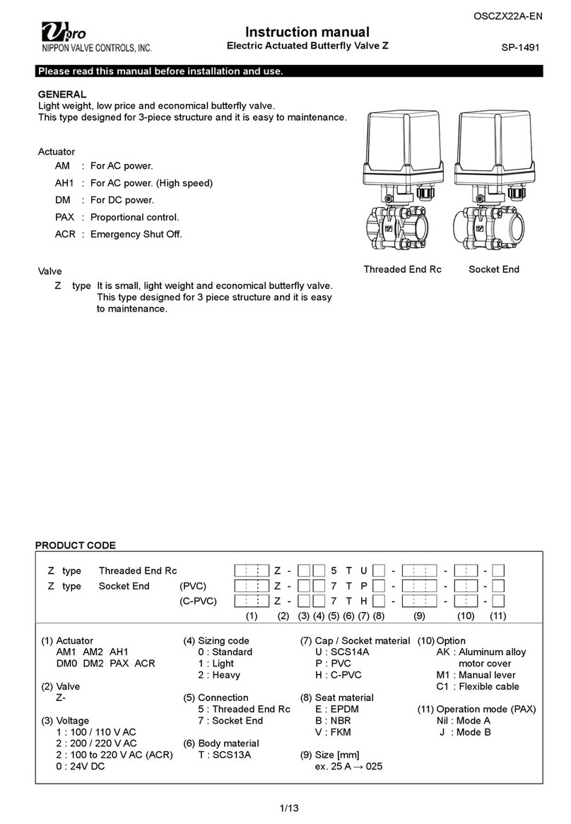
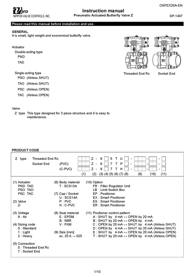
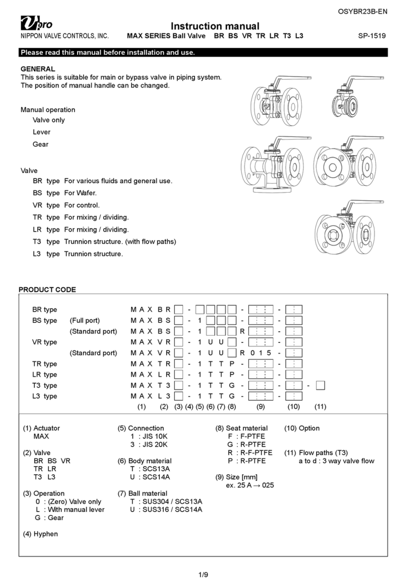
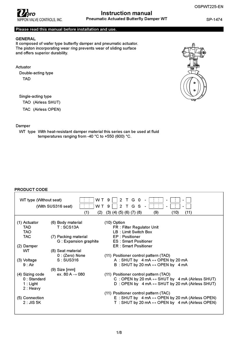
NIPPON VALVE CONTROLS Vpro BR User manual

OSCBR225-EN
1/13
Instruction manual
Electric
Actuated B
all
Valve
B
R
BS
GS
VR
SP-1474
Please read this manual before installation and use.
GENERAL
Flange-end ball valve and compact electric actuator.
Actuator
AM : For AC power.
AH1 : For AC power. (High speed)
DM : For DC power.
PAX : Proportional control.
Valve
BR type For various fluids and general use.
BS type For Wafer
VR type For control
GS type For Wafer. (JIS 10K / 20K)
PRODUCT CODE
BR type (JIS 10K) B R 1 - -
(JIS 20K) B R 3 T T - -
BS type B S 1 - -
VR type (V-port) P A X V R 1 U U - - -
(Reduced port) P A X V R 1 U U R 0 1 5 - -
GS type (V-port) P A X G S 3 U U V - -
(Full port) G S 3 U U - - -
(Standard port) G S 3 U U R 0 4 0 - -
(1) (2) (3) (4) (5) (6) (7) (8) (9) (10) (11)
(1) Actuator
AM1 AM2 AH1
DM0 DM2 PAX
(2)
Valve
BR BS
V
R
GS
(3)
Voltage
1 : 100 / 110 V AC
2 : 200 / 220 V AC
0 : 24V DC
(4) Sizing code
0 : Standard
1 : Light
2 : Heavy
(5) Connection
1 : JIS 10K
3 : JIS 20K
(6) Body material
T : SCS13A
U : SCS14A
(7) Ball material
T : SCS13A
U : SUS316 / SCS14A
(8) Seat material
F : F-PTFE
G : R-PTFE
R : R-F-PTFE
K : PEEK
I : API
C : R-PEEK
M : SUS316 + Stellite
(9) Size [mm]
ex. 25 A ® 025
(10) Option
AK : Aluminum alloy motor cover
M1 : Manual lever
C1 : Flexible cable
(11) Operation mode (PAX)
Nil : Mode A
J : Mode B
BR / VR BS GS

OSCBR225-EN
2/13
VALVES SPECIFICATIONS
Water Oil Air, Gas Steam Chemicals Sea water Slurry Negative pressure
BR BS
VR
type
Valve type BR BS VR
Design 2-way, Full port 2-way, Wafer 2-way, V-port
Connection JIS10K Flanged-end JIS20K Flanged-end JIS Flanges 10K JIS10K Flanged-end
Fluid
Max pressure 1 MPa 2 MPa 1 MPa 1 MPa
Size [mm] 015 to 032 015 to 025 015 to 032 015 to 025
Material Body SCS14A SCS13A SCS13A SCS13A SCS14A SCS14A
Ball SCS14A SCS13A SCS13A SCS13A SCS14A SUS316 / SCS14A
Seat F-PTFE R-PTFE F-PTFE R-PTFE R-PTFE
R-F-PTFE R-F-PTFE R-F-PTFE
Stem seal Packing R-PTFE R-PTFE R-PTFE
O-ring FKM FKM FKM
The optional for steam fluids.
Valve type Option code O-ring
BR BS
V
R ST Replace (Steam resistant FKM)
PRESSURE & TEMPERATURE RATING
BR (JIS 10K) BR (JIS 20K) BS VR
Note) Insulation options are required for use with fluids more than 150 °C.
INHERENT FLOW CHARACTERISTIC (VR)
Cv value (%)
Valve opening (%)
Range ability
V
R-1UUG - 015 to 025
V
R-1UUG R 015
50:1
100:1

OSCBR225-EN
3/13
VALVES SPECIFICATIONS
Water Oil Air, Gas Steam Chemicals Sea water Slurry Negative pressure
GS type
Valve type GS
Design 2-way, Wafer
Connection JIS Flanges 10K / 20K
Fluid
Max pressure 2 MPa
Size [mm] 015 to 040
Material Body SCS14A
Ball SCS14A (HCr PLTD)
Seat R-PTFE PEEK API R-PEEK SUS316 + Stellite
Stem seal Packing R-PTFE
PRESSURE & TEMPERATURE RATING
Note) Option for use in fluid temperature more than 170 °C.
SEAT LEAKAGE VOLUME
Seat material Leakage rate Remarks
G R-PTFE We prefer to K seat depends on pressure
or environmental conditions. please consult
us for your specifications.
API cannot be used with steam fluid.
K PEEK Bubble-tight
I API
C R-PEEK Less than 0.00001 % of rated Cv.
(V-ported type is 5 to 8 times the above.)
1/1000 of ANSI B16.104 Class IV.
M SUS316 + Stellite Less than 0.01 % of rated Cv.
(V-ported type is 5 to 8 times the above.)
ANSI B16.104 Class IV.
Note) M seat can also be manufactured at ANSI B16.104 Class V.
INHERENT FLOW CHARACTERISTIC
Cv
value (%)
Valve opening (%)
Range ability
GS-3UU V 015 to 032
GS-3UU - 015 to 032
GS-3UU R 040
50:1
200:1
100:1

OSCBR225-EN
4/13
ELECTRIC ACTUATOR SPECIFICATIONS
AM1 AM2 type
Actuator type
(:Voltage code) AM1-030- AM1-070- AM1-180- AM2-030- AM2-070- AM2-180-
Voltage 100 / 110 V AC ±10 % 50/60 Hz (Voltage code: 1)
200 / 220 V AC ±10 % 50/60 Hz (Voltage code: 2)
Rated torque [Nm] 3 7 18 3 7 18
Operation time [s] 5.4 / 4.5
(50/60 Hz)
15.5 / 13
(50/60 Hz)
16 / 13.5
(50/60 Hz)
5.4 / 4.5
(50/60 Hz)
15.5 / 13
(50/60 Hz)
16 / 13.5
(50/60 Hz)
Power consumption [VA] 16 19 18 19
Motor Synchronous motor
Overload protection Thermal protector
Method of operation Transfer input type a-contactinput type, with built-in relay
Operation Power to S ® SHUT (SHUT PL is lit.)
Power to O ® OPEN (OPEN PL is lit.)
SW is OFF ® SHUT (SHUT signal is output.)
SW is ON ® OPEN (OPEN signal is output.)
Input signal current Nil 9 mA (O-terminal)
Leakage current in SW: less than 1 mA
Output signal rating Resistance load 3 A 250 V AC
(Minimum 0.1 A)
Resistance load 0.5 A 125 V AC
2 A 30 V DC
Micro load 1 mA 5 V DC
Duty cycle 20 % 15 min.
Ambient temperature -20 to 55 ºC
Space heater 1 W
Manual operation Direct operation of actuator by loosening lock screw
Enclosure Equivalent to IP65 (IEC 60529)
Housing material Aluminum alloy die cast + Polycarbonate resin cover
Terminal block For bare wire 0.14 to 1.5 mm² (AWG 26 to 14) Ground terminal: M4
Conduct port G3/8 Cable gland (for 5 to 10.5 mm cable)
WIRING
AM1 AM2
• Control switch should be prepared one by one for
actuator. Do not operate two or more actuator from
one switch. It might malfunction.
• Two or more actuators can be operated with one
control switch.
• When using control switch with current leakage
(more than 1 mA) such as TRIAC or relay with CR,
it can cause malfunction.
Voltage
100/110V AC
200/220V AC
TP
SH
SHUT PL
OPEN PL
Ground terminal(M4)
S.LS
O.LS
TP
SHUT signal
OPEN signal
S.LS
O.LS
Motor
control
Space
heater
circuit
Voltage
100/110V AC
200/220V AC
Ground terminal(M4)

OSCBR225-EN
5/13
ELECTRIC ACTUATOR SPECIFICATIONS
AH1 type
Actuator type ( :Voltage code) AH1-030- AH1-070- AH1-180-
Voltage 100 / 110 V AC ±10 % 50/60 Hz (Code: 1)
200 / 220 V AC ±10 % 50/60 Hz (Code: 2)
Rated torque [Nm] 3 7 18
Operation time [s] 3 / 2.5 (50/60 Hz) 6 / 5 (50/60 Hz)
Power consumption [VA] 19 50
Motor Synchronous motor Reversible motor
Overload protection Thermal protector
Method of operation Transfer input type
Operation Power to S ® SHUT (SHUT PL is lit.)
Power to O ® OPEN (OPEN PL is lit.)
Output signal rating Resistance load 3 A 250 V AC (Minimum 0.1 A)
Duty cycle 20 % 15 min.
Ambient temperature -20 to 55 ºC
Space heater 0.5 W 1 W
Manual operation Direct operation of output shaft
Enclosure Equivalent to IP65 (IEC 60529)
Housing material Aluminum alloy die cast + Polycarbonate resin cover
Terminal block For bare wire 0.14 to 1.5 mm² (AWG 26 to 14) Ground terminal: M4
Conduct port G3/8 Cable gland (for 5 to 10.5 mm cable)
WIRING
Note) Control switch should be prepared one by one for actuator.
Do not operate two or more actuator from one switch. It might malfunction.
TP
SH
S.LS
O.LS
Voltage
100/110V AC
200/220V AC
SHUT PL
OPEN PL
Ground terminal(M4)

OSCBR225-EN
6/13
ELECTRIC ACTUATOR SPECIFICATIONS
DM0 DM2 type
Actuator type DM0-030-0 DM0-070-0 DM0-180-0 DM2-030-0 DM2-070-0 DM2-180-0
Voltage 24 V DC
Rated torque [Nm] 3 7 18 3 7 18
Operation time [s] 0.8 to 1.5 2 to 3 4 to 6 2 to 3.5 2 to 3 4 to 6
Power consumption (Max)
[VA] 24 10 24
Motor DC motor
Overload protection Thermistor
Method of operation Switching polarity type a-contactinput type, with built-in relay
Operation
2
+
3
- ® SHUT (SHUT PL is lit.)
3
+
2
- ® OPEN (OPEN PL is lit.)
SW is OFF ® SHUT (SHUT PL is lit.)
SW is ON ® OPEN (OPEN PL is lit.)
Input signal current Nil 16.2 mA (O-terminal)
Output signal rating Resistance load 2 A 30 V DC Resistance load : Less than 1 A 24 V DC
Micro load 1 mA 5 V DC
Duty cycle 20 % 15 min.
Ambient temperature -20 to 55 ºC
Space heater 1 W
Manual operation Direct operation of output shaft
Enclosure Equivalent to IP65 (IEC 60529)
Housing material Aluminum alloy die cast + Polycarbonate resin cover
Terminal block For bare wire 0.14 to 1.5 mm² (AWG 26 to 16)
Conduct port G3/8 Cable gland (for 5 to 10.5 mm cable)
WIRING
DM0 DM2
Voltage
24V DC
SHUT PL
OPEN PL
Motor control
circuit
PTC
PTC
RY
RY
S.LS
O.LS
Voltage
24V DC
SHUT PL
OPEN PL

OSCBR225-EN
7/13
ELECTRIC ACTUATOR SPECIFICATIONS
OPTIONAL PARTS
Specifications Code No. AM AH1 DM Remarks
Aluminum alloy motor cover AK
Manual lever M1 Detachable lever
Flexible cable (Approx. 300 mm long) C1
DIMENSIONS
AM (030 / 070) DM2 (030) DM0
(030)
DM
(070)
AH1 (030 /
070) AM (180) DM (180) AH1 (180)
Parts name
1 Body 4 Control board 7 Drive gear
2 Motor cover 5 Terminal block 8 Drive shaft
3 Motor 6 Limit switch 9 Rubber packing
107
36
74
99
58 2
5
3
4
1
9
6
8
85
36
74
126
107
2
5
3
4
1
9
6
8
107
85
53
74
140
7
2
5
4
3
9
6
8
1

OSCBR225-EN
8/13
ELECTRIC ACTUATOR SPECIFICATIONS
PAX type
Actuator type ( :Voltage code) PAX-050- PAX-120-
Voltage 100 / 110 V AC ±10 % 50/60 Hz (Code: 1)
200 / 220 V AC ±10 % 50/60 Hz (Code: 2)
Rated torque [Nm] 5 12
Operation time [s] 14 / 12 (50/60 Hz) 30 / 25 (50/60 Hz)
Power consumption [VA] 9.5
Motor Synchronous motor (Triac control)
Overload protection Impedance protect
Method of operation Proportional control
Input signal 4 to 20 mA / 1 to 5 V (Input resistance: 250 )
Operation *¹ [Mode A] SHUT by decreased signal « OPEN by increased signal (Standard)
[Mode B] SHUT by increased signal « OPEN by decreased signal (Option: J)
Indication signal 0 mA : SHUT « 1 mA : OPEN (External load resistance: less than 3 k)
Common in mode A / B
Resolution Less than 0.2 %
Duty cycle 100 %
Ambient temperature -20 to 55 ºC
Space heater 1 W
Manual operation Direct operation of actuator by loosening lock screw
Enclosure Equivalent to IP65 (IEC 60529)
Housing material Aluminum alloy die cast + Polycarbonate resin cover
Terminal block For bare wire 0.2 to 1.5 mm² (AWG 26 to 16) Ground terminal: M3
Conduct port G3/8 Cable gland (for 5 to 10.5 mm cable)
*¹ Change by DIP switch. (Standard ® Mode B)
WIRING
Setting with DIP switch
Mode A / B is selected simply by setting the mode
change DIP switch located on built-in control board.
Mode A Mode B
Note) • Input signal circuit is non-isolated. Do not connect DC (-) wire to other DC (-) common.
• Do not adjust operating angle of a valve (OPEN/SHUT trimmer).
Please contact us if you need to adjust operating angle.
Input signal
4 to 20mA
1 to 5V
Indication signal
0 to 1mA
Voltage
100/110V AC
200/220V AC
Ground terminal(M3)
Trimmers
Operation
range
Potentiometer
1kΩ
Dead band
Indication
signal

OSCBR225-EN
9/13
ELECTRIC ACTUATOR SPECIFICATIONS
OPTIONAL PARTS
Specifications Code No. PAX Remarks
Aluminum alloy motor cover AK
Flexible cable (Approx. 300 mm long) C1
Operation SHUT by decreased signal « OPEN by Increased signal Nil Mode A
SHUT by increased signal « OPEN by decreased signal J Mode B
DIMENSION
PAX (050) PAX (120)
Parts name
1 Body 4 Control board 7 Drive shaft
2 Motor cover 5 Terminal block 8 Rubber packing
3 Motor 6 Potentiometer
ADJUSTMENT (PAX)
Dead band
Turn the trimmer clockwise for wide the dead band as necessary.
It is useful to prevent the hunting reaction of actuator.
*Each trimmer on a built-in control board.
Operating range
Do not adjust operating angle of a valve (OPEN, SHUT trimmer).
Please contact us if you need to adjust operating angle.
Operating speed (Speed control)
No adjustment required. (ZERO, SPAN trimmer)
36
107 74
126
85
1
2
6
3
4
5
7
8
74
53
107
140
85
1
2
6
3
4
5
7
8
T1
POWER
SPAN
ZERO
SHUT OPEN D.B.
T2
ON
↑
I-
4~20 mA
I+ +
1
S1
0~1 mA
-
DIP SW
Adjustment trimmer

OSCBR225-EN
10/13
INSTALLATION, OPERATION & MAINTENANCE INSTRUCTIONS
HANDLING & STORAGE
HANDLING
Do not drop or throw the product as it may break.
STORAGE
Store away from dust, moisture and direct sunlight.
If possible, store in the original package.
CHECKING
• Check the product code, power supply, and voltage
before installation.
• Make sure that the bolts are not loose.
• The DIP switch should be set up before the power is
turned on. Do not touch unnecessary switches.
(PAX)
INSTALLATION
PRECAUTIONS
• Flush the pipeline carefully before installing the
valve. Foreign particles, such as sand or pieces of
welding electrode, will damage the ball and seats.
• For valves with specified flow direction (GS / VR) or
with ST / SC option, check the arrows on the product
before piping.
PIPING FLANGES
• Gasket should be selected appropriately to suit the
fluid, pressure and temperature.
Use spring washer to prevent from decreasing
surface pressure gasket when the temperature
change happens frequently.
• Tighten all bolts using crossover method to load the
joint evenly.
• Wafer type ball valve is put between two seats of
flanged-end and tightened with long bolts. (BS / GS)
ENVIRONMENT
• Do not install in place where corrosive gas is present
or where vibration is heavy (0.5 G or more).
• When radiant heat causes the surface temperature
of the control unit to exceed 55 °C, provide an
appropriate shielding plate.
• If there is a possibility that the fluid and drive part
freeze, please take measures to prevent freezing.
POSITIONING
Should be positioned through 90° upward from
horizontal. Provide space around the product to
allow manual operation, inspection and replacement
work.
Margin required around the actuator for maintenance
AM (030 / 070) DM2 (030) More than 65 mm
AM AH1 DM PAX More than 90 mm
OTHER NOTES
Until the wiring is completed there must be no
condensation or flooding in the interior of the
actuator, after piping. Protective caps on the cable
gland are not waterproof.
CAUTIONS FOR MAINTENANCE (GS)
Do not keep warm for maintenance of the valve
gland.
TIGHTEN THE GLAND NUTS (GS)
• Check that there is no leakage from the gland
packing.
• If it leakage, tighten gland nuts by alternately.
Do not over-tighten the gland nuts.
Recommended torques
Valve size [mm]
Torque [Nm]
GS
V-port Full port Standard port
015
020
015
020 - 2
025
032
025
032 040 3.5
WIRING
• Do not wiring outdoors on a rainy day.
• Check the power supply and voltage.
Connect the signal as shown in the wiring diagram.
• Do not connect unnecessarily terminal.
• Use suitable flexible cable (5 to 10.5 mm).
Lock and seal the cable completely to prevent
condensation inside the actuator.
• Built-in terminal block can clamp up to 1.5 mm in
diameter without using solderless terminal.
• Allow proper cable slack for maintenance.
• Actuator should be electrically grounded.
Use the terminal marked ( ) inside the actuator.
PREVENT DEW CONDENSATION
• When installing the cover after wiring, perform the
bolt by the temporary tightening procedure and the
permanent tightening procedure to tightly and
securely tighten the rubber packing so that water
does not enter from the outside.
• Tighten the cable gland nut so that there is no
leakage from the wire entrance.
Gland nut
Gland plate
Stem

OSCBR225-EN
11/13
INSTALLATION, OPERATION & MAINTENANCE INSTRUCTIONS
CONTROL
AM1 / AH1
Control switch should be prepared one by one for
actuator. Do not operate two or more actuator from
one switch. It might malfunction.
AM2
• Two or more actuators can be operated with one
control switch.
• When using control switch with current leakage
(more than 1 mA) such as TRIAC or relay with CR,
it can cause malfunction.
• When wiring is long distance or handling a weak
current signal, it may be affected by induced voltage
or noise. In this case, please use countermeasures
such as using a shielded wire, separating it from
other power cables.
DC POWER SUPPLY
• It is usable with a battery and full-wave rectification
circuit.
• Consider an inrush current of motor.
(It is 1.5 to 3 times of consumed current.)
• They may cause malfunction with decreasing voltage
by the long wiring.
• Do not use power supply that require more than
1 second with rise and fall time.
USE OF OPEN/SHUT SIGNALS (AM / AH1 / DM)
Use signals within the capacity of output signal
rating.
PAX
• Use shielded wire for signal wiring where high level
noise is generated or when the wiring distance is
long.
• Control with a 1 to 5 V input signal becomes an input
resistance 250 . Provide a voltage that can safely
20 mA or more than.
• Check whether the MODE change DIP SW on a
circuit board substrate is set up correctly.
When wiring, if wiring of a signal is mistaken, it will
not operate correctly. Contact us when you use two
valve or more by one controller or indicator.
• Input signal circuit is non-isolated.
Do not connect DC (-) wire to other DC (-) common.
• The input signal and operation mode are set as
follows. (Factory shipped)
Input signal 4 to 20 mA / 1 to 5 V
Operation mode Mode A
Operation SHUT by decreased signal
OPEN by increased signal
OPERATION
TESTING
• Make sure that power supply voltage is correct. Also
check operating position, wiring, speed and signals.
• During trial operation, check that valve movement
and output signal are correct.
DUTY CYCLE (AM / AH1 / DM)
Confirm that the operation frequency is within the
specified duty cycle.
Use beyond the load time rate range will affect
product life. Also, it may cause burnout.
Duty cycle is a value that regulates the opening /
closing frequency of the actuator. The meaning of
20 % 15 minutes for Duty cycle is that 3 minutes
(20 % of 15 minutes) operation is possible.
The calculated value obtained by dividing 3
minutes by the operation time is the number of
times of operation within 15 minutes.
CONFIRM THE OPERATING CONDITION (PAX)
• Adjust fluid condition, controller setting, sensor etc.
so that stable control is achieved.
• When used in an unstable control state, the life of
the actuator and the valve will be shortened.
• The desired control state is stable at the target value.
Adjust the PID setting value of the controller when
overshooting the target value greatly, when not
converging for a long time or hunting operation. Also,
when the time delay is large, please consider the
sensor position.
ATTENTION
• Be sure to set the DIP-SW before turning on the
power supply. (PAX)
• Keep power supplied for built-in space heater to
prevent condensation inside actuator.
• Do not touch the moving parts of actuator in
operation.
• Do not insert a reverse signal during operation.
It may shorten the life of product. (AM / AH1 / DM)
• Never put anything on the actuator or make it into a
foothold.

OSCBR225-EN
12/13
INSTALLATION, OPERATION & MAINTENANCE INSTRUCTIONS
MANUAL OPERATION
PRECAUTIONS
• Manual operation should be a temporary operation.
• Be sure to turn off the power before manual
operation.
NOTE
For manual operation, do not give more than the
rated torque and make at a slow rate. Actuator might
be damaged if excessive force is added.
AM PAX AH1 DM
Actuator can be easily
removed from the valve
by loosing 3 lock
screws, and that allows
direct operation of the
valve. After operation,
be sure to put back the
actuator to the original
position and lock.
Put an allen wrench
(5 mm) or a lever
(5.7) into the hole on
drive shaft and turn
slowly.
Manual lever is
optional.
MAINTENANCE
• To prevent electric shock, be sure to turn off the
power when removing the actuator cover.
• Do the routine maintenance at least once in half a
year.
Inspection items
• Confirm operation of opening and closing.
• Confirm that an actuator is not hot excessively.
• Confirm existence of abnormal noise and
vibration during operation.
• Confirm whether screws are loose or not.
• Confirm that water or condensation no remains
in the actuator.
• Confirm the fluid temperature or pressure.
• Confirm the leak from valve stem.
• Confirm the bolt tightening torque.
Lock
screws

OSCBR225-EN
Document is subject to change without notice.
NIPPON VALVE CONTROLS, INC.
1-21-19 Meieki minami, Nakamura-ku, Nagoya 450-0003 JAPAN
TEL: 81-52-582-6435 FAX: 81-52-582-6439
13/13
INSTALLATION, OPERATION & MAINTENANCE INSTRUCTIONS
TROUBLE SHOOTING
Problem Cause Solution
Actuator
does not
move.
Faulty wiring. Correct the wiring.
No voltage is
coming.
Check the voltage.
Incorrect
voltage.
When it's burned out by
excess voltage, replace
the actuator.
Connection or
wiring is not
correct. (PAX)
Correct the miswiring
and misconnection.
Be careful not to
mistake the plus and
minus of wiring.
Short the
circuit, contact
failure.
Review wires and
connection.
Motor is too
old.
Replace the actuator.
Operation is
unstable.
Excess surge
or voltage was
applied.
Replace the actuator.
Rainwater
entered the
actuator.
Switch
leakage
current is
large. (AM2)
Current leakage should
be less than 1 mA.
Operation is
unstable.
(PAX)
Added high
harmonics
noise from an
inverter.
Attachment a filter for
each inverter maker
option.
Effect of high
level noise.
Use the shielded wire
and ground the wiring.
Separate signal wire
from power line.
Stop in the
mid position.
(Input
signal’s
1 to 5 V.)
(PAX)
Signal voltage
source
capacity
shortage.
Use a voltage source
that can be made to
flow more than 20 mA.
Please contact us.
Stop in the
mid position.
Continuous irregular stop will shorten
the motor life and wear the gear.
Turn off the power and check.
(AM1 AM2 AH1-030)
Problem Cause Solution
Stop in the
mid position.
• Biting of
valve seat.
• The scale
has adhered
to the valve
ball.
Remove a foreign
object.
Overload
protector runs
because of
over-torque.
Turn off the power for
about 3 minutes to
remove a heat from
motor protection circuit.
(AM AH DM)
Motor protection circuit
returns by the signal of
operation of an
opposite direction. Turn
on the power again.
(PAX)
Leakage
from
valve body
• Valve cap
get loose.
• Valve body
is damaged.
Replace the valve.
Leakage
from
valve seat
Seat is worn
or damaged.
Replace the valve.
Replace the valve seat.
Leakage
from
valve stem
Stem packing
is worn or
distorted.
Replace the valve.
Replace the packing.
Leakage
from valve
gland (GS)
Gland packing
is worn or
distorted.
Tighten the gland nut.
Replace the gland
packing.
For more information contact
NIPPON VALVE CONTROLS, INC. for consultation.
This manual suits for next models
3
Table of contents
Other NIPPON VALVE CONTROLS Control Unit manuals
Popular Control Unit manuals by other brands

Festo
Festo Compact Performance CP-FB6-E Brief description
EOS
EOS EmoTouch 3 operating instructions
Mutable Instruments
Mutable Instruments Clouds user manual
Siemens
Siemens LOGO! Series manual
axing
axing SKF 40-00M Operation instructions
MOGAS
MOGAS Watson Series Installation, operation and maintenance manual
Kohler
Kohler K-10668 Homeowner's guide
Redi Controls
Redi Controls RuptureSeal RS-2 operation & maintenance
Powers
Powers IntelliStation Jr User guide and instruction manual
USR IOT
USR IOT USR-BLE100 user manual
DH Instruments
DH Instruments PG7600 installation instructions
SMC Networks
SMC Networks S0700 Installation and maintenance manual
