Nipro PHOENIX ONE User manual

Operator´s Manual
Reverse Osmosis
TYPE: PHOENIX ONE
Date: 13.01.2021 |Version: 6
Written by:Rüdiger Tille

Foreword
This Operator’s Manual includes all information required for the installation and operation for the
reverse osmosis model Phoenix One.
Please keep this Operator’s Manual readily available and near the unit.
This Operator’s Manual applies for the units with the serial number:
© Copyright 2020
Nipro Pure Water GmbH
Werner-von-Siemens-Str.2-6
76646 Bruchsal –Germany
Tel.: 0049 7251-32 19 7810
Fax: 0049 7251-61 89 943
Rev#
Date / Name
Description
0
12.12.09 / N.Bürkle
First edition
1
28.02.14 / N.Bürkle
Nipro
2
20.12.19 / N.Bürkle
New Design / EMV
3
10.01.20 / N.Bürkle
Air pressure added
4
25.02.20 / N.Bürkle
gem. EN60601
5
01.12.20 / N.Bürkle
EMC information
6
13.01.21/ R.Tille
60Hz Version
For the reverse osmosis type Phoenix One, conformity according to
EC directives is declared
0297

Version 6| 13.01.2021 |Page 3
3
1 General
1.1 Water quality
Microbiologic Quality
The microbiological quality of the dialysis water depends on a number of factors. Neglecting a
factor could result in poor quality.
Examples of these factors:
▪Quality of the inlet water (potable water)
▪Reverse osmosis rinse intervals and the type and frequency of disinfection of the dialysis
water system
▪Disinfection method of the water inlet side of the dialysis machines
▪General center hygiene (e.g. frequency of connecting or disconnecting dialysis machines
to the dialysis water system)
Chemical quality
In order to receive an indication of the water quality, the conductivity of the water is measured.
The conductivity is a measure of the amount of dissolved salts in the water and can be used as
a performance parameter for osmosis.
Caution
Conductivity alone does not give 100% certainty that the water is suitable for dialysis. Therefore,
regular checks of the chemical water quality must be carried out
1.2 Scope of supply
The scope of delivery includes the following parts:
▪1 reverse osmosis
▪1 connection set
1.3 Unit combinations
The unit model Phoenix DS may be combined with the following devices:
Hot cleaning system Phoenix One +
Hot cleaning system Phoenix One +FH
Version 6| 13.01.2021 |Page 4
4
1.4 Accessories and Consumables
▪1 Prefilter 20“ 10µm
1.5 Notes for the Operator
The operator is responsible for:
Competent and intended operation
Compliance with work safety and accident prevention provisions
Technical instruction of operating personnel
1.6 Laws and Standards
The following laws and standards are adhered to:
Council Directive 93/42 EEC Medical Devices
EN 60601
DIN EN 1717 Protection of potable water against contamination
1.7 Symbols used in this Manual
Stands for a dangerous situation. Disregard can result in personal injury or
material damage.
Stands for information and valuable tips.

Version 6| 13.01.2021 |Page 5
5
1.8 Transport and Storage
Protect unit against frost and moisture
Protect against strong jolting and collisions.
Only move unit upright and with an appropriate lift.
1.9 Model Plate
Attention, take note of
accompanying documents
CE mark with the number of
the notified body. Here DQS
IPX 4
Protection against the
ingress of liquids. Here
splash-water protection
Protection Scheme according
to EN 1717. Here free outlet
Serial number
Year of construction
manufacturer
pay attention to manual

Version 6| 13.01.2021 |Page 6
6
1.10 Warning on the Unit.
Caution! Hot surface. Attached to the tank.
Caution voltage. Turn mains switch off before opening housing. Fixed on
control cabinet.
1.11 Shutdown
If a unit is shutdown for more than 5 days, conservation will be necessary.
Please contact Nipro Pure Water before performing conservation.
1.12 Disposal
Regarding the WEEE guidelines of the European Union, the disposal of electronic devices and
electronic sub-assemblies and parts into the general garbage is not lawful. These parts must be
disposed environmentally appropriate:
If not appointed otherwise and no private disposal management is available, these devices or
possibly other environmental hazardous items can be sent back.
The filters and membrane can be disposed via the general garbage

Version 6| 13.01.2021 |Page 7
7
1.13 Instruction / Further Documentation
The using personnel must be warned against the hazards during operation and must be warned
against the hazards of misusing the product.
The personnel gets the instruction of operation and the specialties of usage. Instructed adult only
are allowed to operate this device.
This instruction by the manufacturer or authorized personnel takes place during the
commissioning of the device.
Further trainings are not necessary for this device.
For qualified personnel the following documents can be made available upon request.
▪Circuit diagrams
▪Spare parts list
▪Technical manual
If the system is operated in combination with the hot cleaning system Phoenix One + or hot
cleaning system Phoenix One + FH, an extension to these operating instructions is available.
1.14 Duration of usage
The device is designed for a use of 10 years
Version 6| 13.01.2021 |Page 8
8
2Intended operation
The unit is designed for the preparation of potable water. The pure water (permeate) thus
produced may be used for dialysis treatment.
Other applications are only possible after consulting the manufacturer and receiving their
approval.
The unit can only be maintained by the manufacturer or technicians trained by
the manufacturer.
Only original replacement parts may be used for maintenance and repairs.
Installation operations, modifications or reparations, are only allowed to be
performed by persons authorised by the manufacturer and may only be done
with original replacement parts. Improper performed reparations or modifications
can lead to hazards to the user and/or may damage the system.
The device may only be operated in perfect condition.
Before operating, check the following:
−Lose or defect parts
−Defect cables and/or isolations
−Serious soiling
The device may only be operated with the appropriate ring line.
The system does not produce water for injections.
The device has pressurized parts.
If the temperature sensor fails, the temperature in the permeate can increase.
(Max 60°C)
The water treatment system Phoenix One may only be used for permeate supply
of dialysis devices, which have a temperature measurement (permeate
temperature).

Version 6| 13.01.2021 |Page 9
9
The device has no direct patient contact and no patient application part.
2.1 Contraindications / side effects
None

Version 6| 13.01.2021 |Page 10
10
3Safety
3.1 Risk Assessment
There will be no dangers associated with the reverse osmosis model Phoenix One D if the
operating instructions are followed.
The device can automatically start by way of an auto-start.
3.2 EMC
The device was developed and tested in accordance with current standards. Nevertheless,
influence through electromagnetic fields cannot be completely excluded.
3.3 Emissions
The device does not produce dust or vibrations.
The noise level is under 609 dB (A).

Version 6| 13.01.2021 |Page 11
11
4Technical Data
Permeate performance / Feed quantity
Number of membranes
2
3
4
5
6
7
8
Permeate performance
l/h [15°C]
700
1050
1400
1750
2100
2450
2800
Feed quantity min. at 3
bar dynamic
2000
2500
3000
3500
4000
4500
5500
Inlet water
Quality
Potable Water
Hardness
< 1 °dH
Silicate
< 25 mg/l
Chlorine
< 0,1 ppm (mg/l)
Iron
< 0,1 ppm (mg/l)
SiO2
< 30 ppm
Fouling Index (S.D.I)
< 3
Temperature
5-30°C
Conductivity
<1500µS/cm
pH
6,5-8,5
Pressure
3-6 bar
Connections
Water feed
G 1” external
Permeate connection
TriClamp d50,5 DIN
Drain
HT 50
Electrical data
Phoenix ONE
Supply voltage
400 V, 3 Phases, 50 Hz
400 V, 3 Phases, 60 Hz
Fuse
Automat 16 A-K, Fi ΔI
30mA
Automat 16 A-K, Fi ΔI
30mA
Output
3,5 KW
3,5 KW
Degree of pollution
1
1

Version 6| 13.01.2021 |Page 12
12
Display system
Conductivity
0-1000 µS/cm ±5%
Pressure sensor
0-20 bar ±5%
Water meter
1impl/l ±1%
Flow
0-3000 l/h ±1%
Ambient temperature
Storage / transport
1-40°C
Operation
10-35°C
Relative humidity
< 90% at 20°C not
condensing
Air pressure
795-1062 hPa
Size
Type
Size in
(LxBxH in mm)
1-4 Membranes
1330x800x1650
5-8 Membranes
1330x950x1650
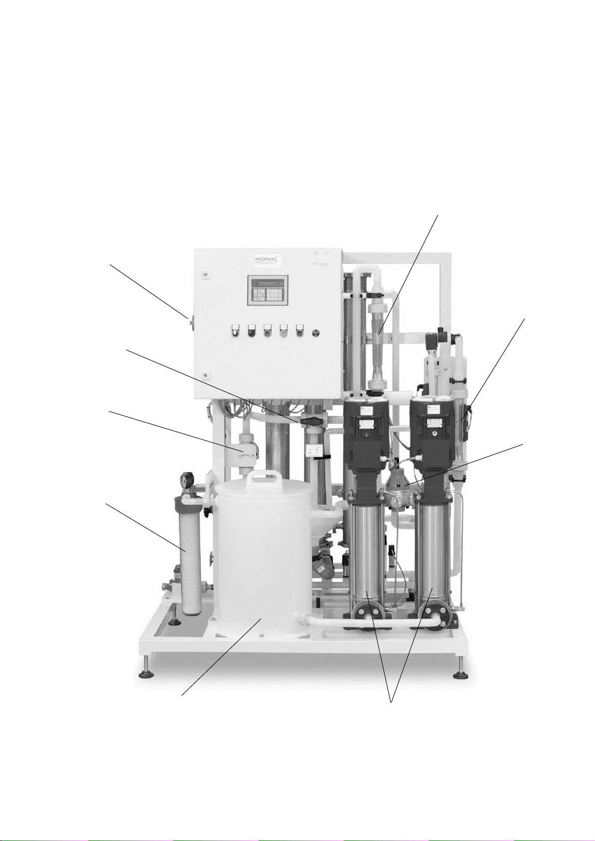
5Description of the device
4
N
6
D
P
T
P
L
D
P
2
D
D
1
35
7
31
8
10
12
11
914
21
26 25 27
28
13
32
24
22
23
29

Version 6| 13.01.2021 |Page 14
14
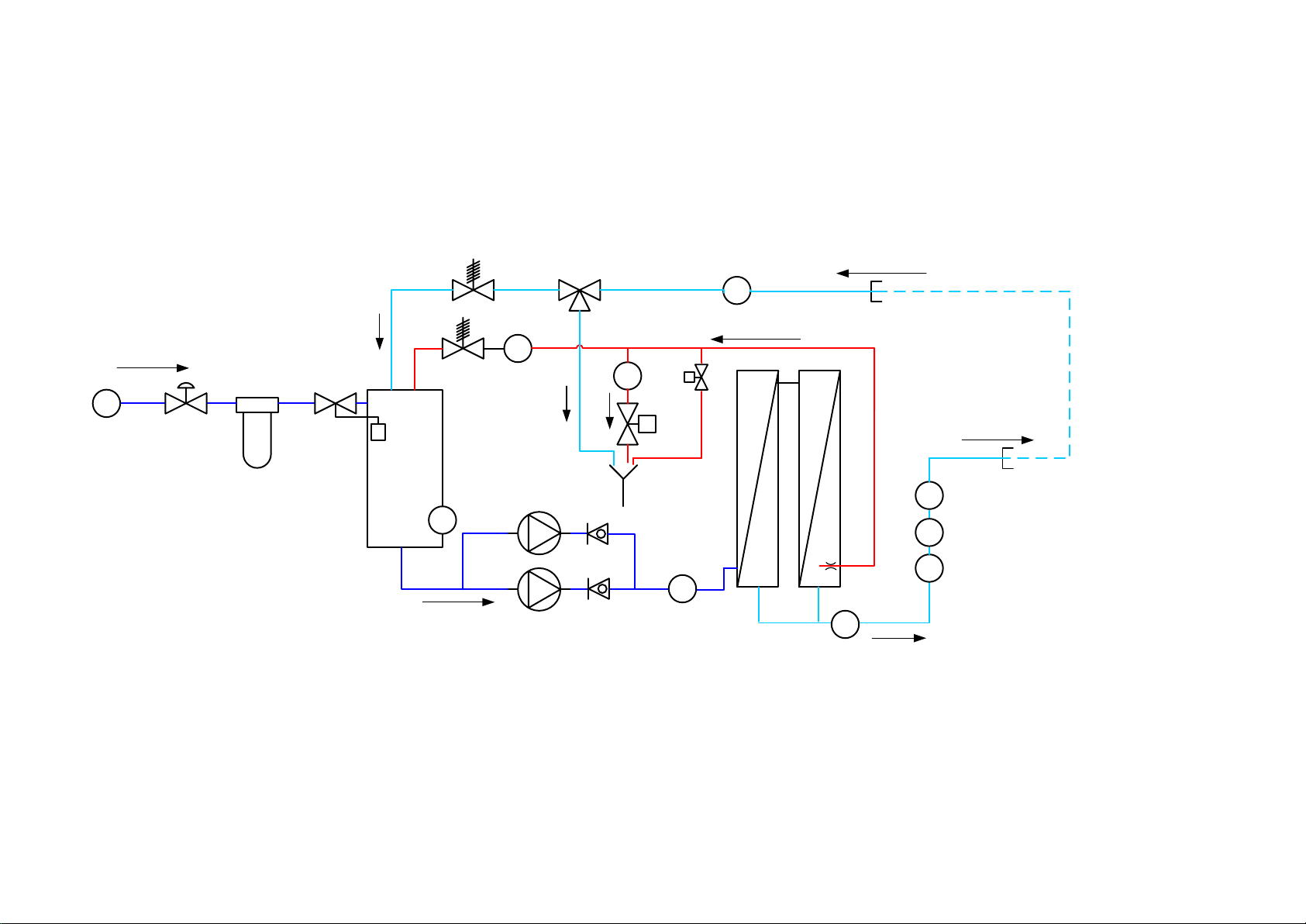
5.1 Flow-Chart
1
Water meter
2
Membrane valve input
3
Fine filter
4
Float valve
5
Dry-run protection
6
Booster pump (Pressure 10-13 bar)
7
Pressure sensor pump pressure
8
Reverse osmosis membrane
9
Flow display Permeate
10
Temperature sensor permeate
11
Conductivity probe
12
Pressure sensor Permeate
13
Not used
14
Ring Flow
15
Not used
16
Not used
17
Not used
18
Not used
19
Not used
20
Not used
21
Flow display Permeate back flow
22
Three way valve permeate to drain
23
Permeate pressure retention valve (Pressure 1-6bar)
24
Pressure retention concentrate
25
Pressure retention concentrate
26
Concentrate valve
27
Flow display concentrate to drain
28
Proportional valve
29
Flush valve
30
Not used
31
2. Booster pump (Option)
32
Ring Back Flow

Version 6| 13.01.2021 |Page 15
15
5.2 Operation Sequence Permeate Production.
Untreated water flow the main through the water line (1) and the fine filter (3) into the break
tank. The float valve (4) mounted in the break tank regulates the water level in the tank.
The booster pump (6) draws the water out of the tank and then presses it into the reverse
osmosis membrane (8). At the reverse osmosis membrane the water stream separates into the
permeate stream (pure water) and the concentrate stream.
The Quality of the produced permeate will be tested with the temperature probe (10) and the
conductivity probe (11). Afterwards it will flow into the ring line to the consumption points.
Unused permeate will be returned to the break tank over the permeate pressure valve (23).
A portion of the concentration will flow through the concentrate valve (26) back into the cycle.
The rest will leave the device through the proportional valve (28) to the drain. The ratio of
concentrate return to concentrate drainage is regulated by the proportional valve (28) based on
consumption.
Version 6| 13.01.2021 |Page 16
16
5.4 Components
Break tank
DIN EN 1717
Booster pumps
Concentrate valve
Prefilter
Pressure retention
valve
Main switch
Through flow display
Permeate flow
Ball valve Permeat
to drain
Through flow display
Permeate back flow

Version 6| 13.01.2021 |Page 17
17
6Installation
The installation must be conducted by the manufacturer or by personnel trained
and authorized by the manufacturer.
6.1 Environmental Conditions
Conditions for the osmosis room:
▪Relative air moisture < 90% at 20°C non-condensing
▪Room temperature between +10°C und +35°C (frost proof)
▪Equipped with floor drain, water supply and electrical supply
6.2 Assembly
▪Bring the system into the appropriate position
▪Adjust machine feet until the device stands level and secure on the floor.
Do not store easily flammable or explosive materials in the vicinity of the device.
Do not store chemicals in the vicinity of the device.
Only operate the device with the necessary water pre-treatment.
Room of osmosis may not be freely accessible. (Access for instructed personnel
only)
Version 6| 13.01.2021 |Page 18
18
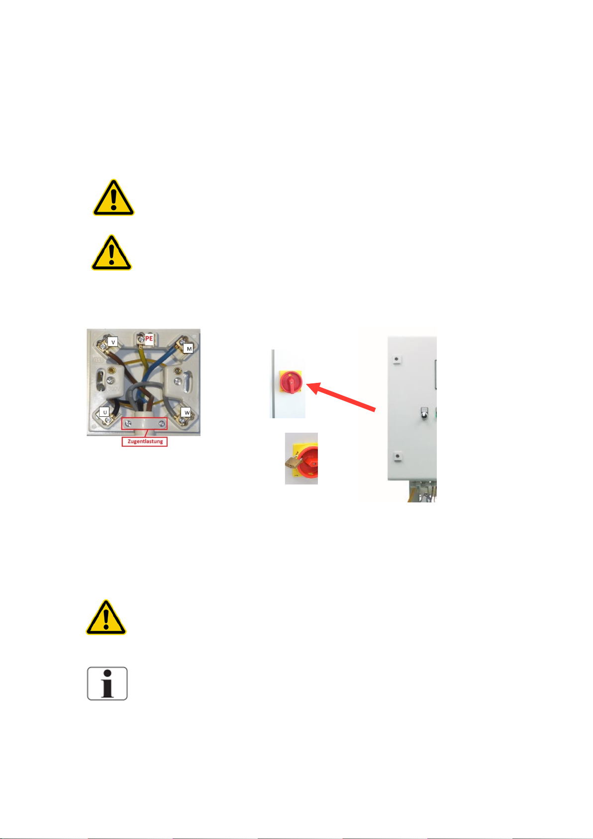
6.3 Electrical installation
The installation may only be performed by a qualified electrician.
The system must be supplied by a permanent connection, connectors are not
valid. The disconnection via the main switch at the control cabinet.
Connection box
Main switch.
For protection against a re-start of the unit, the main switch
can be locked with a padlock.
Safety class I
The device is equipped with a Protective earth terminal for
prevention against high touch current
For prevention of the hazard of an electric shock, this device
may only be connected to a power supply with protective
earth.
The power cord is fixed to the system and cannot be replaced.

Version 6| 13.01.2021 |Page 19
19
Installation plan (Example)
Local water works regulations and DIN EN 1717 must be followed.
The water pre-treatment must be adapted to the local potable water quality.
Version 6| 13.01.2021 |Page 20
20
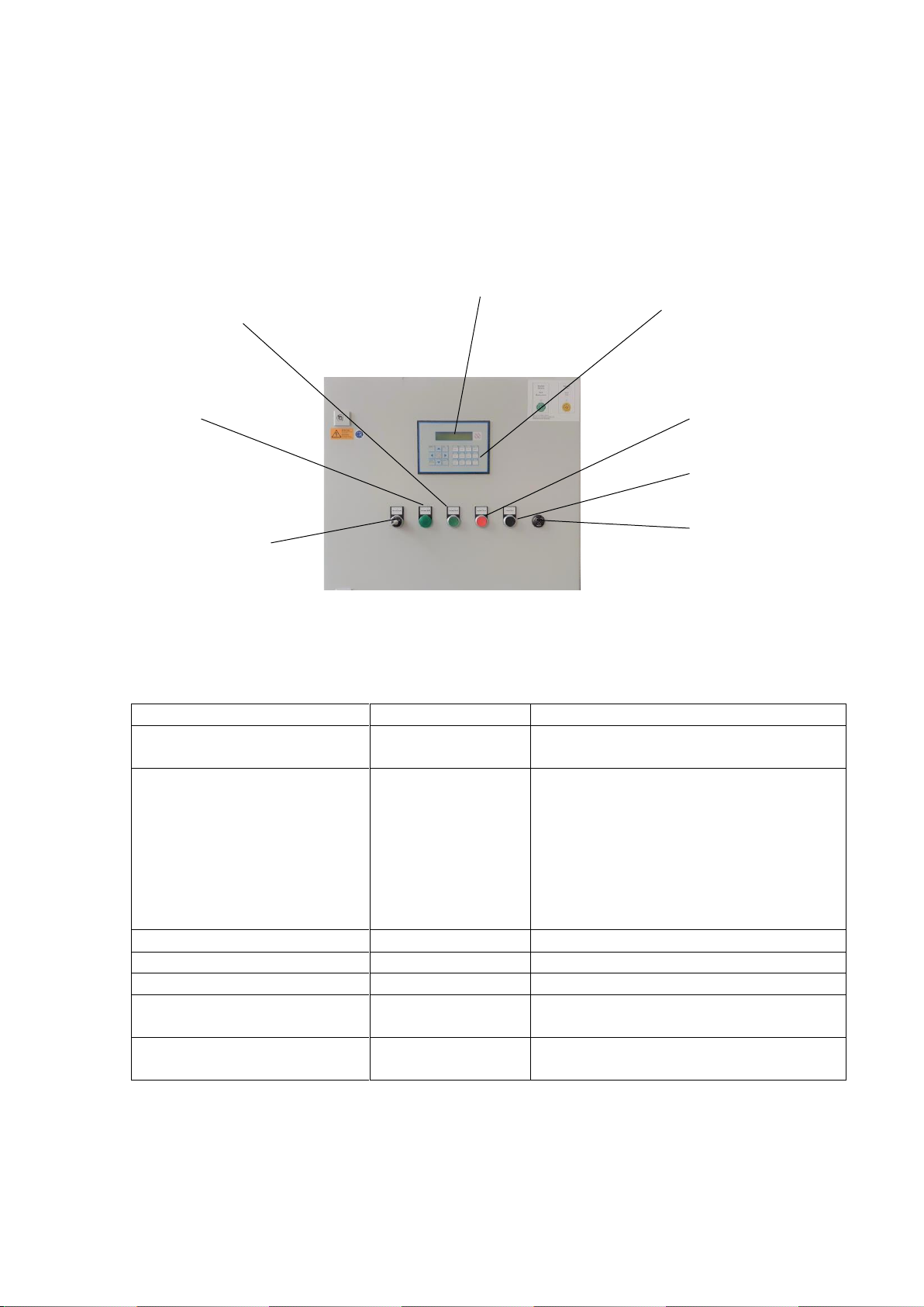
7Operation
7.1 Control Panel
Device Start
Button
Starts the permeate production
Control light unit in operation
Light
If the unit is in operation, this will be
signalled with a green light
Switch manual operation
Switch
Hand, 0, Auto
Switch with three positions:
1 Hand: If the controls fail the
unit can be switched to
emergency operation.
2 0 : Unit off (no clean, no time
start)
Auto: The unit will be operated over by
the controls
Horn
Signal
Horn will activate if an alarm is present.
Horn cancel
Button
Turns off the horn (tone off)
Device Stop
Taster
Stops the device
Keyboard
Call up operation value and settings for
service.
Display
2 lines display
Display operation value and
notifications.
Horn
Keyboard for settings and
call up operation values
Devıce Stop
Horn off
Display
Device Start
Control light unit in
operation
Switch to manual
operation (emergency
operation)
Umschaltung auf
Handbetrieb
(Notbetrieb)
Table of contents
Other Nipro Medical Equipment manuals


