Encision EM2+E User manual
AEM
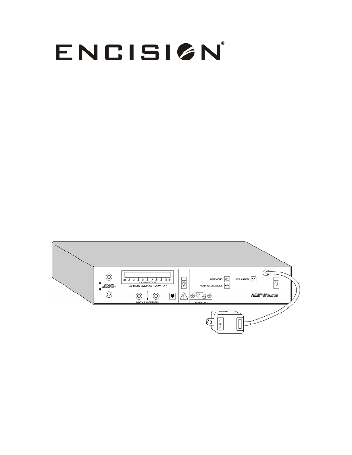
®Monitor
Operator/Service Manual
with AEM® Technology
03614-001

Operator/Service Manual
AEM®Monitor
EM2+E (220-240V)

Manufactured by:
Encision Inc.
6797 Winchester Circle
Boulder, Colorado 80301-3513
Ph: 303-444-2600
Fax: 303-444-2693
Made in USA
Authorized Representative:
MDSS GmbH
Schiffgraben 41
30175 Hannover, Germany
US Patents # 5,312,401 and 5,688,269. Other Patents Pending.
International Patents:
Japan Patent # 2,509,081
Canada Patent # 2,112,817
European Patent Convention # 0596909
Australia Patent # 667322
Trademark acknowledgments:
Encision® is a registered trademark of Encision Inc.
AEM® is a registered trademark of Encision Inc.
REM® is a registered trademark of Covidien/Valleylab
ARM™ is a trademark of ConMed/Aspen Labs
Printed in USA
Part Number: 03614-001 2011/01
© 2011 Encision Inc. All rights reserved.

Table of Contents
Page
Foreword
Indications for Use ...................................................................................................................... i
Contraindications........................................................................................................................ i
Conventions Used in This Manual........................................................................................ ii
Warnings and Cautions...........................................................................................................iii
Symbol Definitions ..................................................................................................................vii
A Accessories-Instructions for Use/Care ....................................................A-1
1 Introduction
Unpacking your System.......................................................................................................1-1
Active Electrode Monitoring ..............................................................................................1-2
Monopolar Surgery................................................................................................................1-2
Bipolar Surgery........................................................................................................................1-2
2 Controls, Indicators, and Receptacles
Front Panel................................................................................................................................2-1
Rear Panel..................................................................................................................................2-3
3 Setup and Tests
Setup of the AEM System (Monopolar) ..........................................................................3-1
Optional Functional Test for Operating Room (before procedure begins) ...........3-3
Checking the Monitoring System (Monopolar)...........................................................3-4
Setup of the End Point Monitoring System (Bipolar) ................................................3-7
Checking the End Point Monitoring System (Bipolar) ..............................................3-9
Mechanical Inspection..........................................................................................................3-9
Electrical Inspection ..............................................................................................................3-9
Cleaning.................................................................................................................................. 3-10
Storing the AEM Monitor.................................................................................................. 3-10
Service Center....................................................................................................................... 3-10
4 Troubleshooting.....................................................................................4-1
5 Principles of Operation
Theory of Operation – AEM (Monopolar) ......................................................................5-1
Circuit Operation (Monopolar)..........................................................................................5-4
Theory of Operation - End Point Monitoring System................................................5-9
Circuit Operation (Bipolar) ..................................................................................................5-9
03614-001

Table of Contents
03614-001
Page
6 Surgical Use
Before Surgery......................................................................................................................... 6-1
Monopolar Surgery ...............................................................................................................6-2
Checking the AEM Monitoring System .......................................................................... 6-3
Bipolar Surgery........................................................................................................................ 6-4
Checking the End Point Monitoring System................................................................ 6-5
General Precautions.............................................................................................................. 6-6
Responding to Monitor Alarms......................................................................................... 6-7
Preparing the AEM Monitor for Reuse............................................................................ 6-8
7 Technical Specifications
Operating Modes – AEM Monitoring.............................................................................. 7-1
Functional Characteristics................................................................................................... 7-2
Indicators and Alert Functions .......................................................................................... 7-2
Connectors and Cables ........................................................................................................ 7-3
Electrical Characteristics......................................................................................................7-5
Dimensions and Weight ...................................................................................................... 7-5
Environmental Characteristics ..........................................................................................7-5
Standards and IEC Classifications..................................................................................... 7-6
Compatible Products..........................................................................................................7-10
8 Replacement Procedures........................................................................ 8-1
9 Repair Policy & Procedures
Obtaining a Return Authorization Number.................................................................. 9-1
Returning the Monitor for Service ................................................................................... 9-1
Limited Warranty.................................................................................................................... 9-3
10 Service Parts..........................................................................................10-1
Service Center
Encision Inc.
6797 Winchester Circle
Boulder, Colorado 80301-3513 USA
(303) 444-2600
www.encision.com
Table of contents
Other Encision Medical Equipment manuals


Popular Medical Equipment manuals by other brands


Getinge
Getinge Arjohuntleigh Nimbus 3 Professional Instructions for use

Mettler Electronics
Mettler Electronics Sonicator 730 Maintenance manual

Pressalit Care
Pressalit Care R1100 Mounting instruction

Denas MS
Denas MS DENAS-T operating manual

bort medical
bort medical ActiveColor quick guide

AccuVein
AccuVein AV400 user manual


