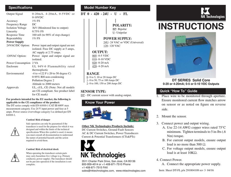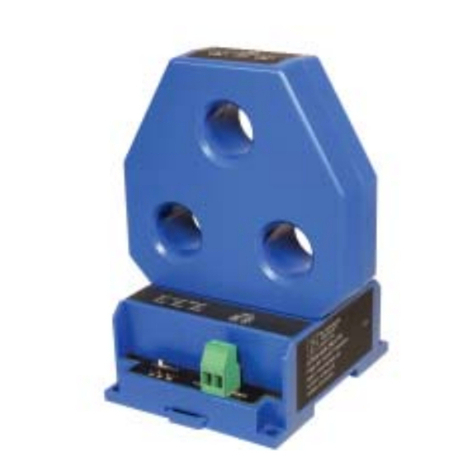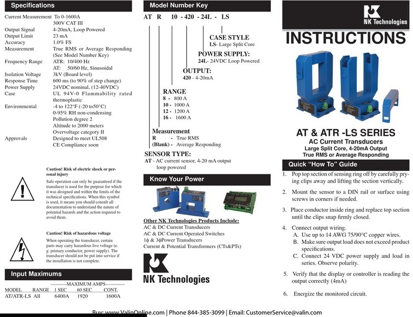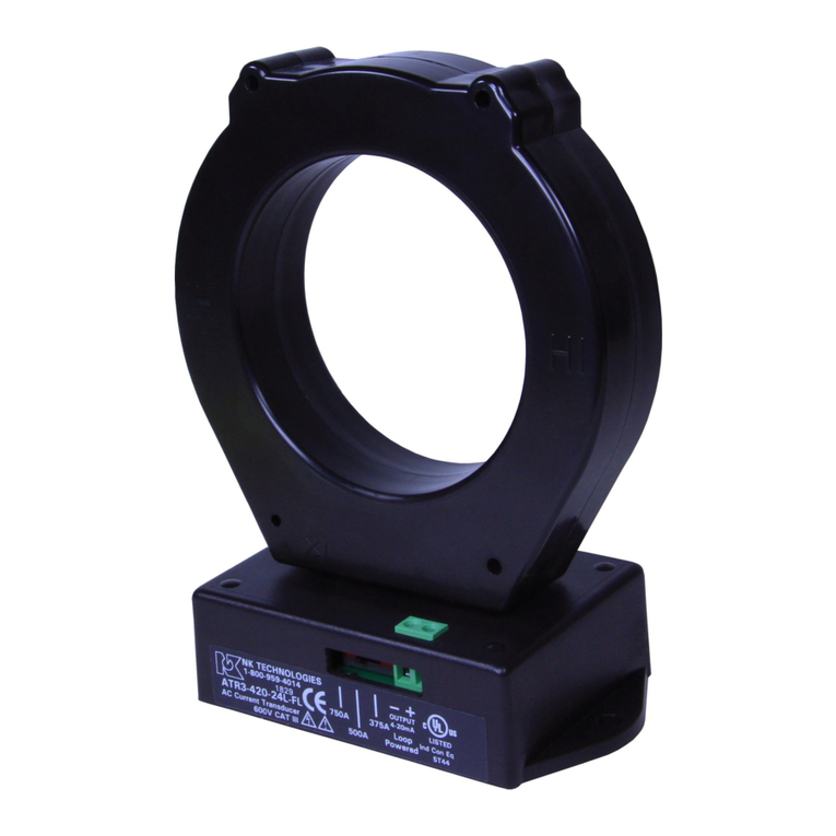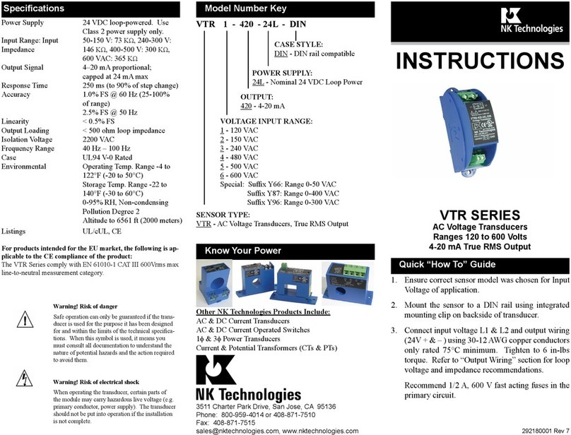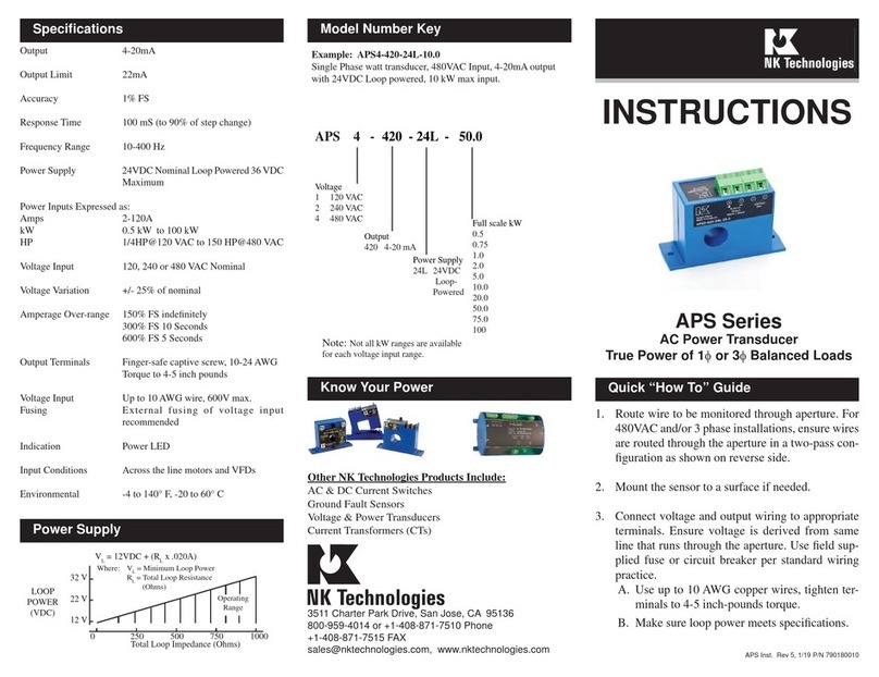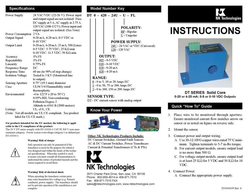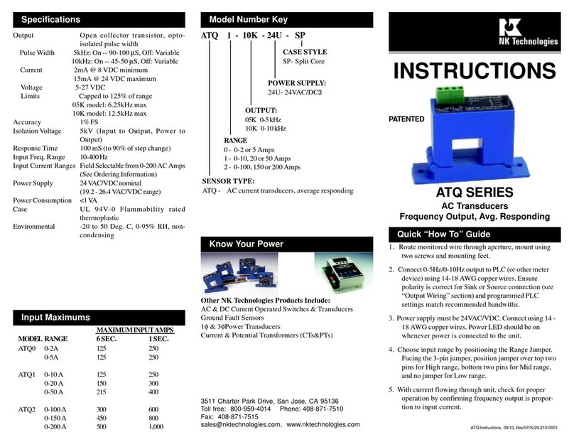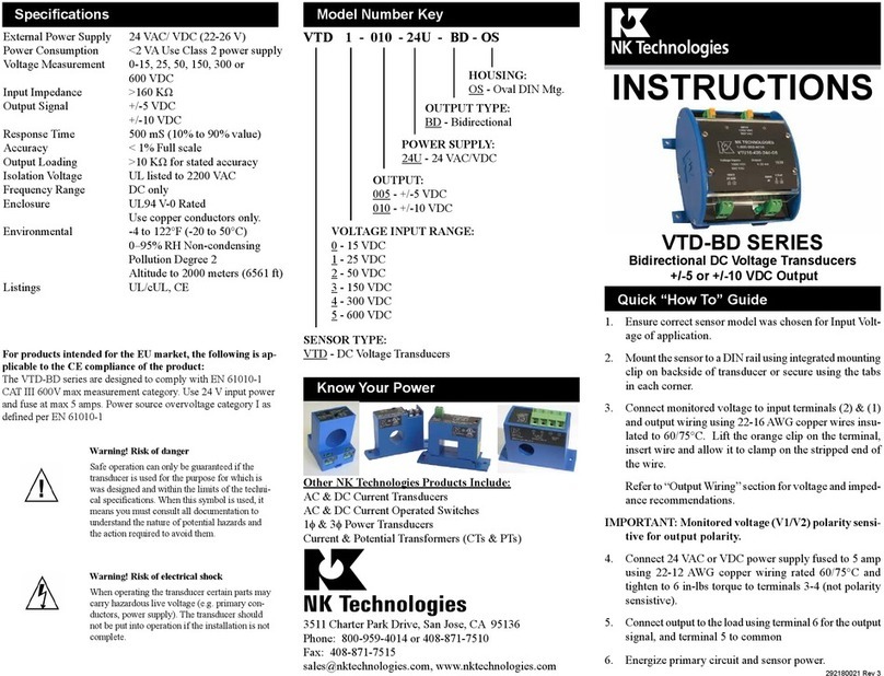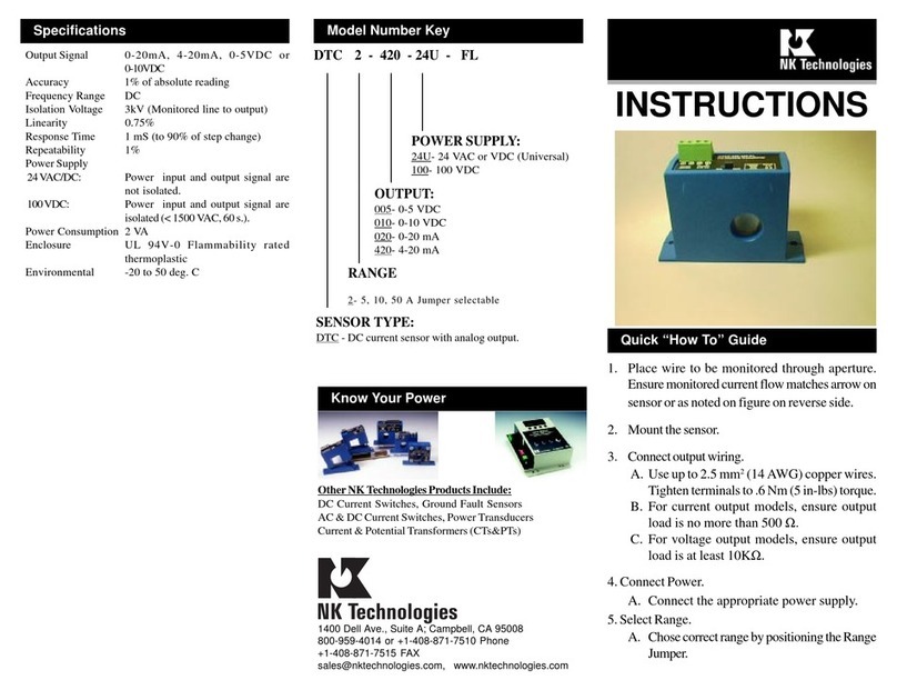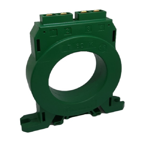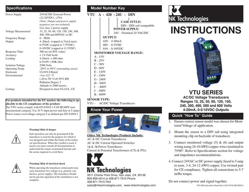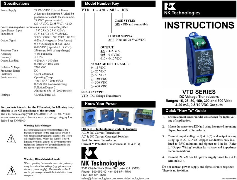
VTU transducers feature a DIN rail compatible enclosure
and are typically located in the same environment as mo-
tors, contactors, heaters, pull-boxes, and other electrical
enclosures.
To mount on DIN rail: Orient transducer so that line volt-
age terminals (1) and (2) are upright/on top of unit and snap
securely onto DIN rail. To remove, insert small screwdriver
into the slots in the lower corners and pry the two mounting
springs down until unit dislodges from DIN rail.
To mount using screws: Insert screws and mount to back
plane or other suitably flat surface.
Description
Installation
Output Wiring
VTU SeriesVoltage Transducers are designed to monitorAC
or DC voltage and detect conditions where supply voltage
is above or below normal. Detecting such conditions helps
users to avoid problems commonly associated with voltage
irregularities such as motor overheating, brownouts and
conductor failure or poor connections.TheVTU isavailable
with 4-20mA, 0-5 or 0-10 VDC output options.
1. Transducer has no output
A. Power supply is not properly sized. Check power supply
voltage and output rating. Each transducer requires less
than 4VA to operate.
B. Green LED should be on when the power supply is en-
ergized.
2. Output Signal Too Low or Too High
A. Transducer model improperly sized for application. Deter-
mine the normal operating voltage of your monitored circuit
and ensure transducer selected is equal to or slightly higher
than the normal operating voltage.
B. Output impedance is higher or lower than needed. Check the
settings of the controller or meter.
3. Sensor is always at 4mA (or zero voltage)
Monitored circuit is not on. Check that the monitored circuit
is actually switched on, and that any fuses used are intact.
Check the power supply if the sensor is designed for voltage
output and the output is reading zero.
4. Sensor is always at 20mA (or 5/10VDC)
Monitored voltage is higher than transducer range. Select a
higher range product.
Troubleshooting Tips
Monitored Voltage Wiring Connection
CAUTION: TO AVOID ANY POTENTIAL FOR SHOCK
OR SAFETY HAZARD, ENSURE MONITORED VOLT-
AGE IS DISCONNECTED AT SOURCE BEFORE WIR-
ING TO UNIT.
Connect voltage to be monitored to terminals (1) and (2)
on transducer using up to 16 AWG copper wires. Lift the
orange clip, insert the stripped wire and release the clip.
Proper torque will be applied.
(mA)
(% FS)
Transducer Output vs. Monitored Voltage
0.0 100.0
50.0
Monitored Voltage
POWER SUPPLY
OUTPUT SIGNAL
4-20mA
0-5VDC
0-10VDC
(1)
(2)
(6)(5)(4)
(3)
Monitored Voltage
GROUND
GREEN LED
POWER ON
Use twisted pair for power supply conductors for full com-
pliance with CE directives.
Note: Voltage output will be linear in the same manner, with
zero at zero monitored voltage and 5 or 10 VDC at the full range
measured voltage.
Connect output signal wires to the sensor. Use up to 14 AWG
copper wire insulated to 75/90°C and tighten terminals 3-6
to7 inch-pounds torque.
5/10VDC
20 mA
0 VDC
4 mA
Output
