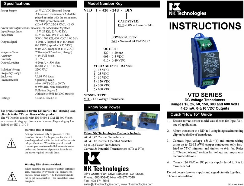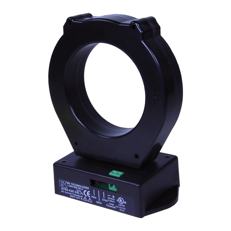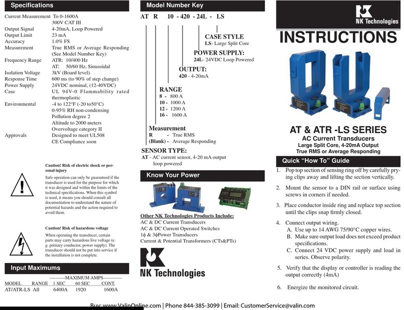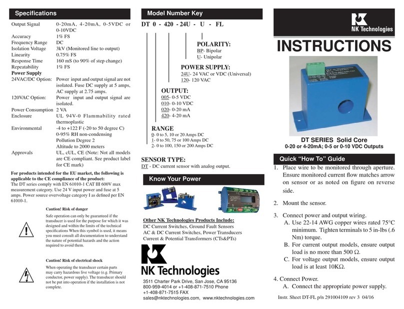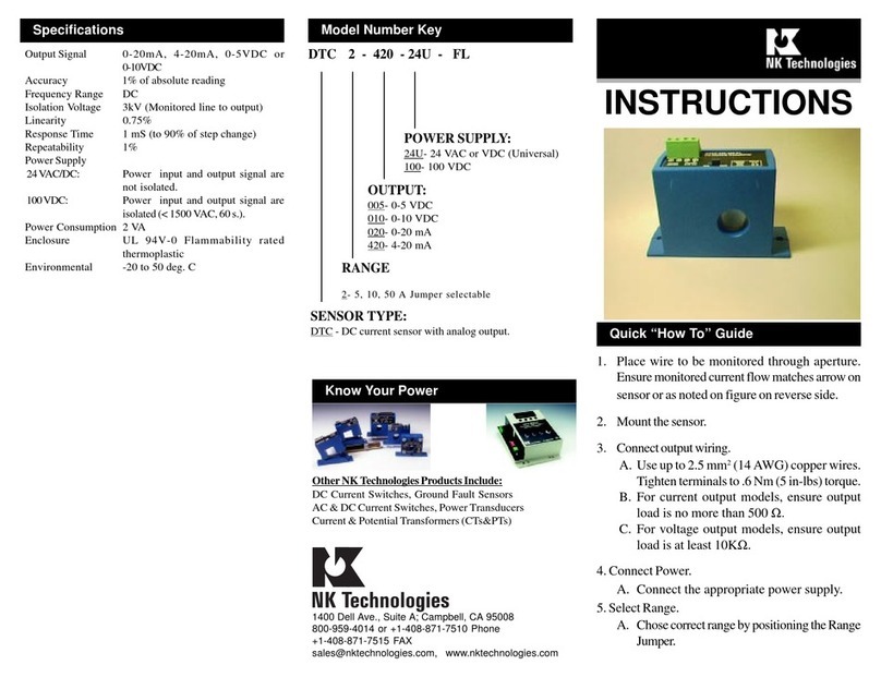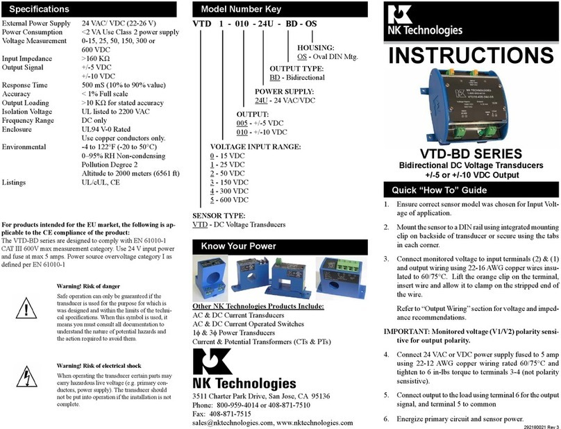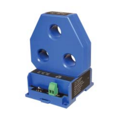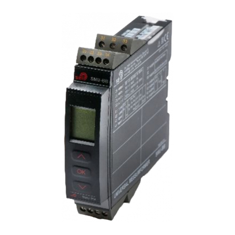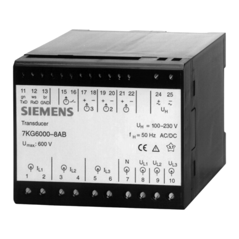
VTR transducers feature a slim DIN rail compatible enclo-
sure and are typically located in the same environment as
motors, contactors, heaters, pull-boxes, and other electrical
enclosures.
To mount on DIN rail: Orient transducer so that line volt-
age terminals L1 and L2 are upright/on top of unit and snap
securely onto DIN rail. To remove, insert small screwdriver
into the lower mounting hole of the spring loaded clip, and
push the handle end of the screwdriver toward the sensor
base to release the tension on the rail.
Description
Installation
Output Wiring
Connect control or monitoring wires to the sensor. Use
30-12 AWG copper wire, insulated to 75°C minimum
and tighten terminals to 6 inch-pounds torque. Be sure
the output load or loop power requirements are met (see
diagram below).
VTR Series Voltage Transducers are designed to monitor
AC voltage and detect conditions where supply voltage is
above or below normal. Detecting such conditions helps
users to avoid problems commonly associated with voltage
irregularities such as motor overheating, damage to drives
due to regeneration, loss of phase and the like.
The VTR is available with a 4-20 mA “True RMS” output
as standard, making them suitable for use in applications
where the monitored voltage is laden with harmonic current
components.
1. Transducer has no output
A. Power supply is not properly sized. Check power
supply voltage and current rating.
B. Polarity is not properly matched. Check and correct
wiring polarity.
2. Output Signal Too Low or Too High
Transducer model improperly sized for application. De-
termine the normal operating voltage of your monitored
circuit and ensure transducer selected is equal to or
slightly higher than the normal operating voltage.
3. Sensor is always at 4 mA
Monitored load is not AC or is not on. Check that the
monitored load is AC and that it is actually on.
Troubleshooting Tips
Loop Voltage Requirements:
LV = 12 V + (LR X 20 mA)
Where: LV = Min. Loop voltage
LR = Loop Resistance
500 Ω maximum impedance
Line Voltage Wiring Connection
CAUTION: TO AVOID ANY POTENTIAL FOR SHOCK OR
SAFETY HAZARD, ENSURE LINE VOLTAGE IS DISCON-
NECTED AT SOURCE BEFORE WIRING TO UNIT.
Connect input voltage to be monitored to terminals L1 and
L2 on transducer using 30-12 AWG copper wires and tighten
terminals to 6 inch-pounds torque. For multiple transducer
applications on separate phases, ensure all phase relationships
between L1 and L2 are consistent.
Fusing of the primary voltage inputs is recommended. Use
a 1/2 amp, 600 V rated fast acting fuse.
To mount using screws: Insert screws and mount to back
plane or other suitably fl at surface.
292180001 Rev 7
