NKT Photonics Koheras HARMONIK Series User manual

Koheras HARMONIK
PRODUCT GUIDE
Low Noise Single Frequency 2nd Harmonic Laser
System

PRODUCT GUIDE
This guide includes the following NKT Photonics products:
Koheras HARMONIK
Low Noise Single Frequency 2nd Harmonic Laser System
Koheras HARMONIK Product Description Revision 1.0 01-2020 W-10456

3
GUIDE OVERVIEW
This product guide is intended to provide functional, operational and installation
information for the Koheras HARMONIK laser systems. The guide is divided into
three sections:
• Koheras HARMONIK Description - introduces the Koheras HARMONIK
system, its functionality, interfaces and variants.
• Installation – includes the details on how to install the system and connect
optional interfaces.
• Operations – – provides information and procedures on how to connect,
configure and manage the system.
The Koheras HARMONIK system consists of four modules. This guide provides
details for the harmonic generator module and its controller. For details on
operating the seed and amplifier lasers, refer to the following documents:
Koheras ADJUSTIK Product Guide
Koheras BOOSTIK HPA Product Guide
Warning: Do not operate the laser before first reading and understanding all
warnings, cautions and handling information stated within the document:
Koheras HARMONIK Safety, Handling and Regulatory Information
Note: The paper copy of this document is included with your laser; however, it
can also be downloaded from:
https://www.nktphotonics.com/lasers-fibers/support/product-manuals/
Target audience This guide is for technical personnel involved in the selection, planning and
deployment of lasers in laboratory and industrial settings. The guide assumes a
reasonable knowledge level of lasers, photonic principles and electrical interface
connectivity.
Chapters inside This guide includes the following chapters:
• Chapter I “HARMONIK System Description” — Describes the laser system
including its general operational principles, management and interfaces.
• Chapter 2 “Optical and Control Module Installation” — Contains information
on installing and connecting the Koheras HARMONIK.
• Chapter 3 “Operations” — Provides information on turning on, connecting,
configuring and operating the Koheras HARMONIK.

4
• Appendices — The appendices contain system specifications and service and
support information.
Added information
and safety notices
Lasers are highly dangerous devices that can cause serious injury and property
damage. This guide use the following symbols to either highlight important safety
information or provide further information in relation to a specific topic.
Note: Highlights additional information related to the associated topic and/or
provides links or the name of the NKT guides describing the additional informa-
tion.
Caution: Alerts you to a potential hazard that could cause loss of data, or damage
the system or equipment.
Warning: The laser safety warning alerts you to potential serious injury that may
be caused when using the laser.
Revision The section records the document revision details.
February 2020 – First release. Note that this document has been rewritten from
an earlier draft release.

5
CONTENTS
Guide Overview ................................................................................................................... 3
TABLES ..................................................................................................................... 7
FIGURES ...................................................................................................................9
1 HARMONIK System Description .....................................................................................11
Models ......................................................................................................................11
Installation ...............................................................................................................11
Optical .......................................................................................................................... 12
Emission beam quality ....................................................................................... 12
Free-space or fiber output ................................................................................ 12
Control module .......................................................................................................... 12
Front panel ............................................................................................................ 12
Rear panel ..............................................................................................................13
Optical module ........................................................................................................... 14
Front panel .............................................................................................................14
Rear panel ............................................................................................................. 15
Optional fiber coupling ...................................................................................... 16
Miscellaneous ............................................................................................................ 16
Safety ...................................................................................................................... 16
CONTROL and CONFIGURATION ........................................................................ 16
Browser User Interface ...................................................................................... 16
Connectivity ...........................................................................................................17
Chassis labels ............................................................................................................. 18
2 Optical and Control Module Installation .......................................................................21
General ........................................................................................................................ 21
Requirements ....................................................................................................... 21
Room Requirements ........................................................................................... 21
Electrical Supply Requirements ...................................................................... 22

6
Installing the system ................................................................................................22
Control module .................................................................................................... 23
Seed and amplifier modules ............................................................................ 23
Connecting the system ........................................................................................... 23
3 Operations ..........................................................................................................................27
Safety ........................................................................................................................... 27
Damage prevention ................................................................................................. 27
General ........................................................................................................................ 27
Stability .................................................................................................................. 27
Temperature Optimization ............................................................................... 28
Settings Page ....................................................................................................... 28
Turning on the system ............................................................................................29
Connecting to the HARMONIK ............................................................................. 29
First time connecting a PC ............................................................................... 29
Setting the IP address ....................................................................................... 30
Resetting the IP address to default ................................................................. 31
Using the system ....................................................................................................... 31
Initial use ................................................................................................................ 31
Optimizing the second harmonic output ....................................................... 31
Auto Temperature button ................................................................................. 33
Fiber procedures ................................................................................................ 33
A Specifications .................................................................................................................... 35
B Service and support Information ...................................................................................37
Servicing the laser .................................................................................................... 37
“WARRANTY...” Label .........................................................................................37
Opening the modules ........................................................................................37
Support contact details ........................................................................................... 38
Support Email ....................................................................................................... 38
Online support web-page ................................................................................. 38
Shipping address ................................................................................................ 38

7
TABLES
Table 1: HARMONIK system models.................................................................................. 11
Table 2: Status LED conditions.......................................................................................... 13
Table 3: Module labels......................................................................................................... 18
Table 4: Optical module installation requirements ..................................................... 23
Table 5: Mechanical dimensions ..................................................................................... 35
Table 6: Operating and storage environment ............................................................. 35
Table 7: Electrical ................................................................................................................. 35
Table 8: Safety and regulatory compliances ............................................................... 35
Table 9: Mechanical dimensions...................................................................................... 36

8

9
FIGURES
Figure 1: Control module front panel ............................................................................... 12
Figure 2: Control module rear panel ............................................................................... 13
Figure 3: Optical module front panel .............................................................................. 14
Figure 4: Optical module rear panel ............................................................................... 15
Figure 5: Optical module rear panel ............................................................................... 16
Figure 6: BUI Ethernet connectivity ..................................................................................17
Figure 7: Label locations ...................................................................................................................19
Figure 8: Optical module rear panel .............................................................................. 22
Figure 9: Removing the optical input cover ................................................................. 24
Figure 10: Installing the collimator assembly ............................................................... 25
Figure 11: Replacing the optical input cover ................................................................. 25
Figure 12: Settings page .................................................................................................... 28
Figure 13: Browser User Interface – Home Page ....................................................... 30
Figure 14: Browser interface connection settings ........................................................ 31
Figure 15: Browser User Interface – Home Page ....................................................... 32
Figure 16: Warranty seal .....................................................................................................37
white

10

11
1 HARMONIK System Description
The HARMONIK system is a high-power frequency doubled laser system. The system
is modular and consists of the following modules:
• Optical module – the module houses the HARMONIK’s optical components
for frequency doubling the source laser beam.
Specifically, this is a photonic
crystal operating at 50-65° C (for 775 fiber) that ensures high-power delivery.
• Control module - the module houses the electronics required for control and
interface of the optical module.
• Koheras ADJUSTIK – laser seed source. The emission from the ADJUSTIK is
delivered to the BOOSTIK HPA.
• Koheras BOOSTIK HPA – Amplifies the seed laser to provide up to 15 W of
power from the optical module in a standard system. Higher custom power
levels are available on request.
Note:
All modules are specifically aligned at the factory and cannot be replaced with-
out NKTP support.
This guide describes the Koheras HARMONIK optical and control modules in detail.
For details of the seed and amplifier laser modules of the system, refer to the
following NKTP guides:
Koheras ADJUSTIK Product Guide
Koheras BOOSTIK HPA Product Guide
Models
The Koheras HARMONIK system models are listed in
Table 1
. The two systems are
defined in the table by their advantages and particular optical specifications.
Table 1 HARMONIK system models
Installation
The Optical and Control modules are designed to be placed on a table or shelf
installation. The Koheras ADJUSTIK and BOOSTIK HPA modules can be either racked
mounted in a standard 19 inch rack or directly placed on a flat surface such as table or
shelf.
Model Advantage Specification
C7 Low Relative Intensity
Noise (RIN)
RIN: -140 dBc/Hz @ 10 MHz
E7 Narrow line width and low
phase noise
Line width: < 0.2 kHz
Phase noise:-87 dB(rad/√Hz/m) at 10 Hz.
Optical
12
Optical
Emission beam
quality
The beam quality, M2 is less than 1.1 and is suitable for advanced quantum physics
projects such as quantum sensing and laser cooling and trapping. Contact NKT
Photonics to discuss the applications that are possible.
Free-space or fiber
output
By default, the HARMONIK systems are equipped with free-space output apertures. If
a fiber coupling is required, an efficient coupling using NKTP’s unique polarization-
maintaining single mode fiber can be included.
Laser classification
The optical output is classified as a CLASS 4 laser emission.
Control module
The Control module houses a micro-controller and associated electronics used to
control and power the Optical module. The Control module includes a
communications and power port that is connected to the Optical module and an
Ethernet port for communications with a PC for system management functions using
a Browser User Interface (BUI) client.
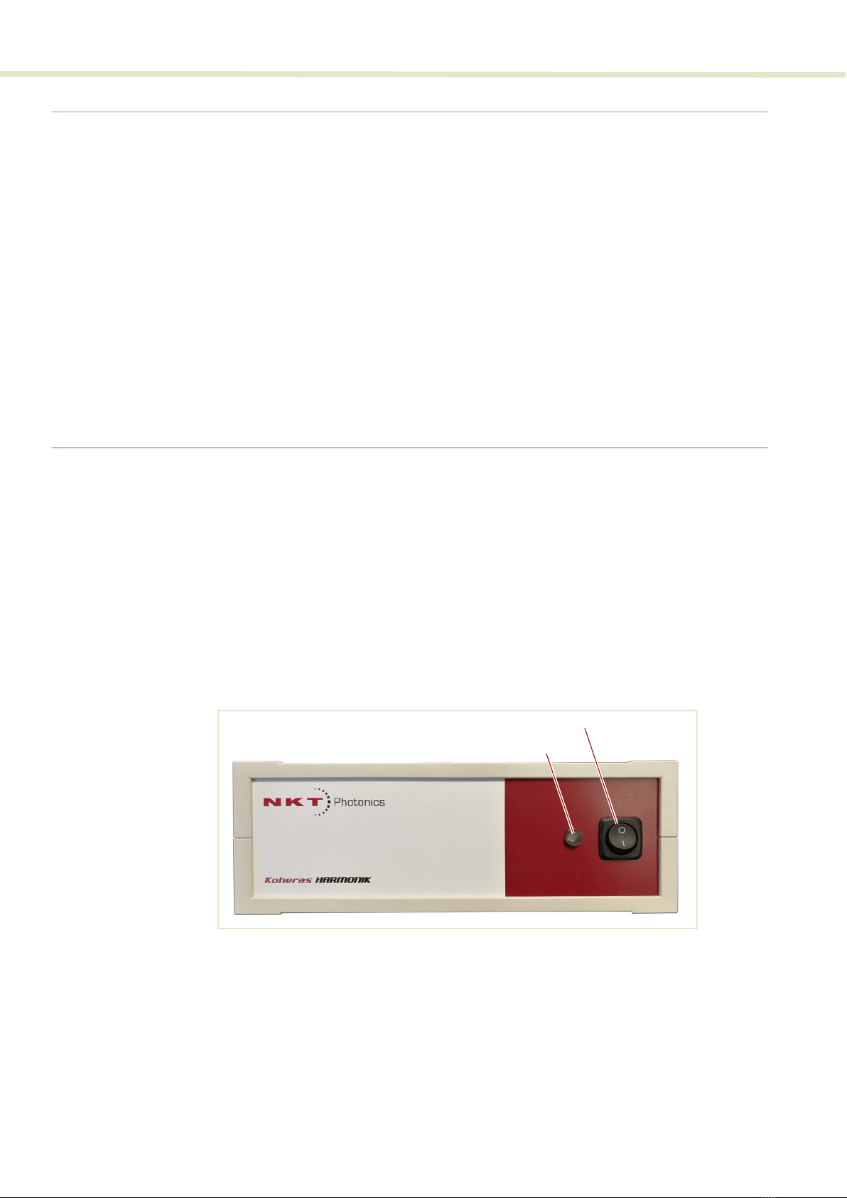
Front panel
The front panel houses a power switch for the module and a single multi-color status
LED.
Figure 1 Control module front panel
Power Switch
Press the switch to ( | } position to turn the control module DC power ON and to the
( O ) position to turn the module DC power OFF.
Power switch
Status LED
13
Control module
Status LED
The front panel LED indicates both when power is applied and if the second harmonic
crystal oven has reached and stabilized at the set point temperature.
Table 2 Status LED conditions
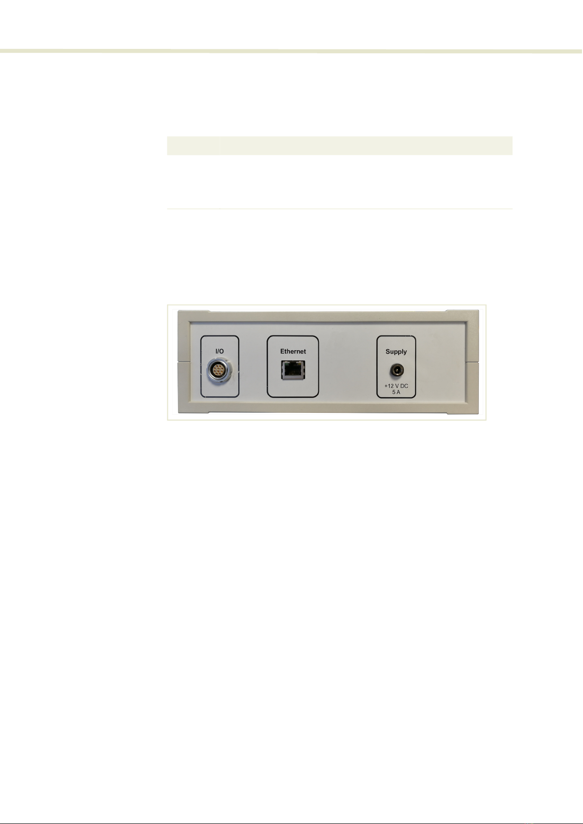
Rear panel
The rear panel houses the communication ports and DC power input for the control
module.
Figure 2 Control module rear panel
IO port
10 pin LEMO female connector – delivers communications and power from the
Control module to the Optical module.
Ethernet port
RJ-45 female connector – provides IPv4/Ethernet access to the Control module from
a PC. The port can be either statically configured or configured as a DHCP client.
Supply
12 VDC 5 A power input – connect to the included power adapter.
Condition Description
ON BLUE Temperature is stabilized at the setpoint i.
i. 50-65° C for 775 nm and 125-135° C for 780 nm
ON RED Temperature has not reached or stabilized at the setpoint.
OFF System switched off or no DC power

Optical module
14
Optical module
Front panel The optical module front panel houses the electrical interfaces and an optical
input assembly in a cut-out along the front and right side panel as shown in
Figure 3.
Figure 3 Optical module front panel
Input laser power – monitor port
SMA connector - Outputs an analog voltage signal proportional to the input
fundamental laser power. Range: 0 to 3.3 V without calibration.
Output harmonic power – monitor port
SMA connector - Outputs a signal proportional to the output second harmonic laser
power. Range: 0 to 3.3 V without calibration.
C
ommunications and power port – 10 pin LEMO connector
Connects the Optical module directly to the Control module. The cable carries data
communications and DC power from the Control module to the Optical module.
Collimator assembly and cover
The assembly consists of a collimator and a holder with alignment pins that insert into
the Optical module chassis for correct alignment. The assembly is aligned at the
factory so that the collimator output is aligned with the input aperture of the optical
module.
1 Input laser power – monitor port 4 Collimator assembly (cover off)
2 Output harmonic power – monitor port 5 Optical input aperture
3 Communications and power port
2
1
5
4
3
Caution: DO NOT REMOVE or LOOSEN
the screws marked with the Caution
symbol in this image.
15
Optical module
Caution: Under no circumstances should the collimator assembly be disassem-
bled by unscrewing the collimator clamp screws.
Optical input aperture
The emission from the BOOSTIK HPA is coupled through the collimator assembly to
the optical input aperture from the factory aligned collimator assembly.
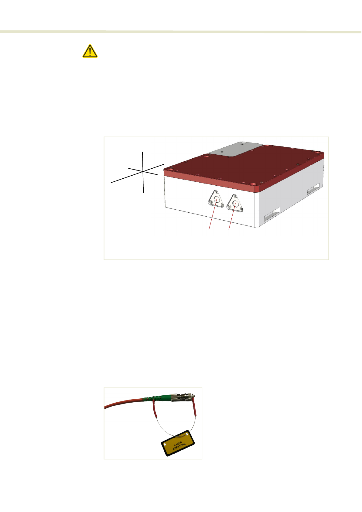
Rear panel
The rear panel houses two free-space output apertures.
Figure 4 Optical module rear panel
Fundamental output aperture
This free-space aperture emits the residual fundamental beam with vertical
polarization (z-axis in
Figure 4
).
Second harmonic output aperture
This free-space aperture emits the second harmonic beam with vertical polarization
(z-axis in
Figure 4
).
Optional fiber
coupling
Pigtail fiber coupling are available as an option and can be fitted to one or both of the
laser output apertures. The polarization axis for a fiber connector output is parallel to
the fiber coupler alignment key.
Figure 5 Optical module rear panel
Fundamental output 2nd Harmonic
aperture output aperture
x
z
y
x

Miscellaneous
16
Miscellaneous
Safety
Warning: The Koheras HARMONIK system emission is rated as Class 4 laser and
is therefore hazardous. Before turning on the laser, ensure to read and under-
stand all safety statements of the document:
Koheras HARMONIK Safety, Handling and Regulatory Information
A paper copy of this document is included with your laser. If you do not have access
it, you can download a copy from:
https://www.nktphotonics.com/lasers-fibers/support/product-manuals/
CONTROL and CONFIGURATION
Browser User
Interface
The Control and Optical modules are managed using a Browser User Interface (BUI)
from a PC connected over IP with the Control module. The BUI can be used to:
• configure the temperature setpoint of the second harmonic conversion
crystal oven
• monitor the input optical power (pump) and the 2nd harmonic output power
(SHG).
• the network interface with a static IP or as a DHCP client.
• perform HARMONIK administrative functions such as:
• firmware upgrade
• shutdown
• reboot
Note:
The seed and amplifier lasers are controlled using NKT Photonics CONTROL
Graphical User Interface (GUI) installed on a PC or the front panel interface. For man-
aging these modules of the system refer to their respective product guides:
Koheras ADJUSTIK Product Guide
Koheras BOOSTIK HPA Product Guide
Note:
DO NOT OPERATE the laser system until you are familiar with the controls and
have taken all precautions necessary for your region and as described in the docu-
ment: Koheras HARMONIK Safety, Handling and Regulatory Information.

17
CONTROL and CONFIGURATION
Connectivity
The Control module can connect to a PC over an IP network using Ethernet. You can
connect the Ethernet port of the module either directly to a PC or to an L2 or L3
network that the PC is connected to.
Figure 6 BUI Ethernet connectivity
L2 or L3
Network

Chassis labels
18
Chassis labels
A Koheras HARMONIK chassis has a number of labels on it that indicate hazards,
regulatory, or manufacturing information. The labels are described in
Table 3
with the
label placements shown in
Figure 7
.
Table 3 Module labels
Label Panel Description
Classification -
Emission
Hazards
Top Safety information stating the laser
emission hazards and the laser’s class
rating.
Product
Information
Top Safety label showing the emission
specifications of the laser.
Manufacturing Side Manufacturing information including
address, part and serial number, date
manufactured and regulatory
compliance.
Laser Radiation
Warning
Top Safety information alert indicating this
area of the laser is near a source of
dangerous laser emissions.
Warranty Seal Side Safety information alert indicating the
location of the aperture where laser
radiation is emitted from the laser. If the
module includes a monitor output, this is
a class 1 laser output and does not
require a a label.
Laser Aperture Rear Safety information alert indicating the
location of the aperture where laser
radiation is emitted from the laser. If the
module includes a monitor output, this is
a class 1 laser output and does not
require a a label.
DANGER - INVISIBLE LASER RADIATION
AVOID EYE OR SKIN EXPOSURE TO
DIRECT OR SCATTERED RADIATION
CLASS 4 LASER PRODUCT
MAXIMUM OUTPUT POWER: 15 W
WAVELENGTH: 500 - 2100 nm
EN60825-1:2014
WARRANTY VOID IF SEAL
IS BROKEN OR REMOVED
LASER
APERTURE
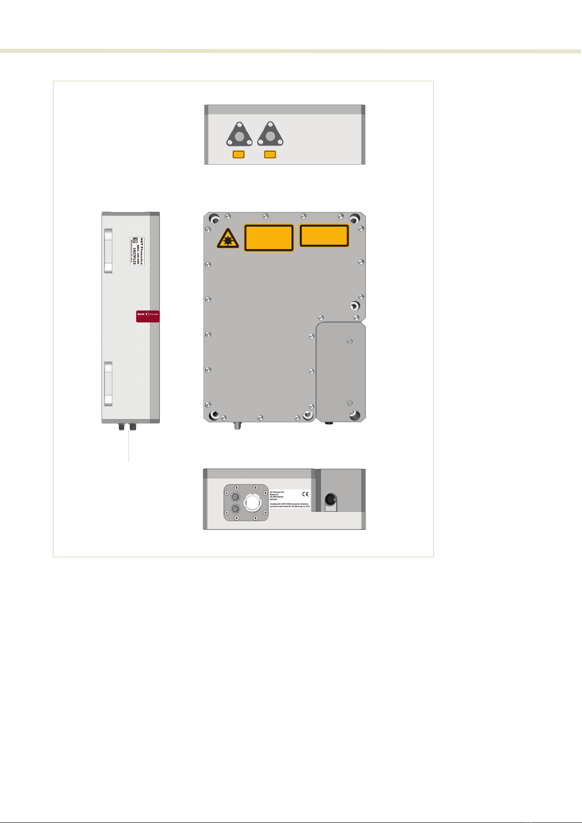
19
Chassis labels
Figure 7 Label locations
DANGER - INVISIBLE LASER RADIATION
AVOID EYE OR SKIN EXPOSURE TO
DIRECT OR SCATTERED RADIATION
CLASS 4 LASER PRODUCT
MAXIMUM OUTPUT POWER: 15 W
WAVELENGTH: 500 - 2100 nm
EN60825-1:2014
LASER
APERTURE
LASER
APERTURE
Rear
Top
Front
WARRANTY VOID IF SEAL
IS BROKEN OR REMOVED
Side

Chassis labels
20
This manual suits for next models
2
Table of contents
Other NKT Photonics Measuring Instrument manuals

NKT Photonics
NKT Photonics ADJUSTIK User manual

NKT Photonics
NKT Photonics PILAS User manual

NKT Photonics
NKT Photonics SuperK EVO User manual

NKT Photonics
NKT Photonics Koheras ADJUSTIK HP User manual

NKT Photonics
NKT Photonics MIKRO C15 User manual

NKT Photonics
NKT Photonics SuperK COMPACT User manual

NKT Photonics
NKT Photonics Koheras ADJUSTIK User manual

NKT Photonics
NKT Photonics SuperK FIANIUM User manual

NKT Photonics
NKT Photonics SuperK FIANIUM FIU-6 User manual

NKT Photonics
NKT Photonics Koheras ACOUSTIK User manual


