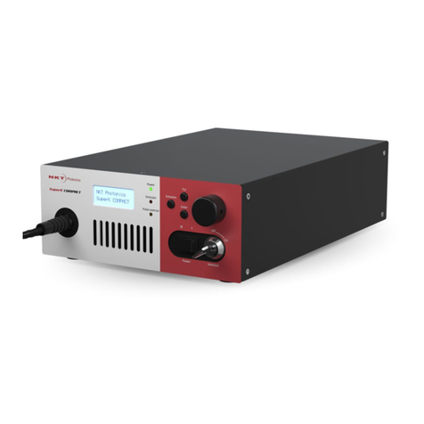
NKT Photonics SuperK CHROMATUNE User manual

SuperK
CHROMATUNE
Product Guide Revision 1.0 09-2023
800-642-01
Select Emission

PRODUCT GUIDE
This guide includes information for the following NKT Photonics products:
SuperK CHROMATUNE
400 to 1000 nm Wavelength Tunable Laser
CAUTION: Do not open the laser chassis. The laser is equipped with warranty
labels (see Figure 83) on the covers of the laser chassis. The warranty is void
if the system is opened.
CAUTION: Do not lift the laser alone. The laser is heavy and weighs close to 20
kg; two people are required to lift the laser when placing it into its packaging.
Manufactured by:
NKT Photonics A/S
Blokken 84, Birkerød-3460 Denmark
The information in this publication is subject to change without notice.
All company and product names mentioned within are either trademarks or registered trademarks of
NKT Photonics.
Specifications are listed as metric units. Imperial units listed are conversions.
Copyright 2023 NKT Photonics A/S. All rights reserved.
NKT Photonics Rev. 1-0 Author: W-10456

<3>
Guide Overview
This product guide is intended to provide functional, operational and
installation information for the SuperK CHROMATUNE laser systems.
WARNING: Do not operate the laser before first reading and understanding all
warnings, cautions and handling information stated within the document:
SuperK CHROMATUNE Laser Safety, Handling and Regulatory Information
The paper copy of this document is included with your laser however it can
also be downloaded from:
https://www.nktphotonics.com/product-manuals-and-documentation/
CAUTION: Use of controls or adjustments or performance of procedures other
than those specified herein may result in hazardous radiation exposure
Target Audience This guide is for technical personnel involved in the selection, planning and
deployment of lasers in laboratory and industrial settings. The guide assumes a
reasonable knowledge level of lasers, photonic principles and electrical
interface connectivity.
NOTE: CHROMATUNE lasers are designed for anyone to operate. Other than
safety measures, laser expertise is not required.
Chapters Inside This guide includes the following chapters:
• Chapter I “Laser Description” — Describes the SuperK CHROMATUNE laser
series including its general operational principles, management and
interfaces.
• Chapter 2 “Mechanical Installation” — Includes information and procedures
on how to correctly install the laser chassis. Procedures within this chapter
focus on providing adequate temperature regulation.
• Chapter 3 “Connecting the Laser” — This chapter provides the information
on how to physically connect the safety interlock, power, the optical
collimator, synchronization interfaces and how to implement external

< 4>
signals to modulate the output, enhance power stability and gate output
pulses.
• Chapter 5 “Overview” — Describes the laser’s front panel menu and
controls that directly operate the laser.
• Chapter 6 “Using Control to Turn On the Laser” — Provides information and
procedures on how to connect to the laser’s management software and
use it to turn the laser emission ON and OFF.
• Chapter 7 “Control Interface” — Includes descriptions and procedures of all
other CONTROL menu and panel items.
• Appendices — The guide includes multiple appendices including laser
specifications, support contact details, pinout information, and
miscellaneous procedures supporting the laser operation and installation.
Added information
and Safety Notices
Lasers are highly dangerous devices that can cause serious injury and property
damage. This guide use the following symbols to either highlight important
safety information or provide further information in relation to a specific topic.
NOTE: Highlights additional information related to the associated topic and/or
provides links or the name of the NKT guides describing the additional informa-
tion.
CAUTION: Alerts you to a potential hazard that could cause loss of data, or dam-
age the system or equipment.
WARNING: The laser safety warning alerts you to potential serious injury when
using the laser.
Revision The section records the document revision details.
Release date Version and changes
09-2023 First release

<5>
Contents
Guide Overview ........................................................................................................................... 3
Figures ....................................................................................................................................... 13
Tables ........................................................................................................................................ 17
Procedures ................................................................................................................................. 19
1 Laser Description ....................................................................................................................... 21
Terminology ................................................................................................................... 21
Maintenance ................................................................................................................... 21
Front panel controls ....................................................................................................... 21
CONTROL ...................................................................................................................... 22
Temperature regulation .................................................................................................. 22
Optical output ....................................................................................................................... 22
Optical specifications ..................................................................................................... 22
Spectral output ............................................................................................................... 22
Collimator ....................................................................................................................... 23
Integrated spectrometer ................................................................................................. 24
Beam diameter ............................................................................................................... 24
Factory test report .......................................................................................................... 24
Output polarization ......................................................................................................... 24
Polarization ring ............................................................................................................. 25
Pulse picker – VRR (optional) .............................................................................................. 25
Repetition rates .............................................................................................................. 25
Using VRR ..................................................................................................................... 26
Output power .................................................................................................................. 26
Reflection monitor ................................................................................................................ 26
Front panel controls ............................................................................................................. 27
Power button .................................................................................................................. 27
Select button ..................................................................................................................27
Display panel ..................................................................................................................27
Power down button ........................................................................................................ 27
Power up button ............................................................................................................. 28
Key switch ...................................................................................................................... 28
Emission button .............................................................................................................. 28
Rear panel............................................................................................................................ 29
CHROMATUNE ports .......................................................................................................... 30

< 6>
Trig in ............................................................................................................................. 30
Trig Out .......................................................................................................................... 30
ASCII out ........................................................................................................................ 30
External control and synchronization BNC ports ................................................................. 30
Pre-VRR ports ................................................................................................................ 30
Post-VRR ports .............................................................................................................. 32
External Feedback ......................................................................................................... 32
Output Control ................................................................................................................ 33
Connecting a PC.................................................................................................................. 33
USB port ......................................................................................................................... 33
RS-232 serial port .......................................................................................................... 34
Ethernet port ..................................................................................................................34
Configuration and operation overview ................................................................................. 34
CONTROL application ................................................................................................... 34
Script interface ...............................................................................................................35
Advanced laser control ................................................................................................... 35
Key switch and interlock safety ...................................................................................... 35
External Bus ...................................................................................................................35
Status LEDs ......................................................................................................................... 36
Chassis labels...................................................................................................................... 37
2 Mechanical Installation............................................................................................................... 39
General installation .............................................................................................................. 39
Installation............................................................................................................................ 40
3 Connecting the Laser................................................................................................................. 41
Connecting the safety interlock............................................................................................ 41
Interlock operation description ....................................................................................... 41
Safety door switch .......................................................................................................... 43
Connecting power ................................................................................................................ 43
Connecting the optical output .............................................................................................. 44
Back reflection ................................................................................................................44
Installing the collimator ................................................................................................... 45
Connecting accessories with the External Bus .................................................................... 46
External Bus ...................................................................................................................46
Connecting the External Bus .......................................................................................... 47

<7>
Connecting pulse synchronization ports .............................................................................. 49
Example synchronization circuit ..................................................................................... 50
Gate out ......................................................................................................................... 50
Pulse out ........................................................................................................................ 50
NIM pulse ....................................................................................................................... 51
Connecting external control ports ........................................................................................ 52
External feedback port ................................................................................................... 52
Output Control ................................................................................................................ 53
4 Front Panel ................................................................................................................................ 55
Overview .............................................................................................................................. 55
Display ................................................................................................................................. 56
Operation ....................................................................................................................... 56
A fault occurs .................................................................................................................56
Notification ..................................................................................................................... 56
Boot-up ........................................................................................................................... 56
Dimming ......................................................................................................................... 56
Operation page .................................................................................................................... 57
Emission parameters ..................................................................................................... 57
Status badge .................................................................................................................. 58
Error page ............................................................................................................................ 59
Error identification .......................................................................................................... 59
Clearing the error message ............................................................................................ 59
Notification page .................................................................................................................. 60
Clearing the notification page ......................................................................................... 60
Operating the laser from the front panel .............................................................................. 60
Front panel operations ................................................................................................... 60
Powering ON and OFF the laser .................................................................................... 61
Rotating the emission parameter positions .................................................................... 62
Adjusting emission parameters ...................................................................................... 62
Set the wavelength ......................................................................................................... 63
Set the bandwidth .......................................................................................................... 64
Set the power ................................................................................................................. 64
Set the repetition rate ..................................................................................................... 65
Arming the laser ............................................................................................................. 65
Enable and disable emission ......................................................................................... 66

< 8>
5 Using Control to Turn On the Laser........................................................................................... 69
CONTROL software............................................................................................................. 69
Installing the software .................................................................................................... 69
Connecting the laser to a CONTROL PC ............................................................................ 69
Ethernet connection ....................................................................................................... 71
Grouping connections .................................................................................................... 73
Controlling laser emission.................................................................................................... 75
Safety ............................................................................................................................. 75
Preparation ..................................................................................................................... 75
Turning ON the laser ...................................................................................................... 76
Errors ............................................................................................................................. 78
Turning OFF the laser emission ..................................................................................... 78
6 Control Interface ........................................................................................................................ 79
Overview ........................................................................................................................ 79
Relocating panels ........................................................................................................... 79
Toggling the panels visible ............................................................................................. 81
Connecting to the laser .................................................................................................. 81
Device Selector.................................................................................................................... 82
Base laser source .......................................................................................................... 82
CHROMATUNE module ................................................................................................. 82
Status Panel – FIANIUM...................................................................................................... 83
Status Indicators ............................................................................................................ 83
Powerlock ....................................................................................................................... 84
System Info ....................................................................................................................84
Emission button .............................................................................................................. 84
Control settings – FIANIUM ................................................................................................. 85
Ethernet .......................................................................................................................... 85
Static network settings ................................................................................................... 86
External Feedback ......................................................................................................... 87
Watchdog .......................................................................................................................88
Clock .............................................................................................................................. 89
View ............................................................................................................................... 89
Status Panel - CHROMATUNE............................................................................................ 90
Status Indicators ............................................................................................................ 90
System Info ....................................................................................................................91

<9>
Script Info ....................................................................................................................... 91
Shutter button .................................................................................................................92
Emission button .............................................................................................................. 92
Control settings – CHROMATUNE ...................................................................................... 92
View ............................................................................................................................... 93
Control panel – FIANIUM..................................................................................................... 94
Normal mode .................................................................................................................. 94
External Feedback mode ............................................................................................... 94
Low emission power ....................................................................................................... 95
Repetition rate ................................................................................................................95
Repetition rates and power modes ................................................................................ 96
Control panel – CHROMATUNE tabs .................................................................................. 97
Control panel tab ............................................................................................................ 97
Sequence tab ................................................................................................................. 97
Control panel tab.................................................................................................................. 98
Control groups ................................................................................................................ 98
Emission wavelength manual controls ................................................................................. 99
Center wavelength ......................................................................................................... 99
Bandwidth ......................................................................................................................99
Lower Upper ................................................................................................................... 99
Adding fluorophore datasets .............................................................................................. 100
Loading fluorophore datasets............................................................................................. 101
Spectrum view.................................................................................................................... 102
Basic ............................................................................................................................ 102
Spectrometer ................................................................................................................ 102
Ex ................................................................................................................................. 103
Em ................................................................................................................................ 103
Dynamic ....................................................................................................................... 104
Mouse over function ..................................................................................................... 104
Power ................................................................................................................................. 104
Power setpoint ............................................................................................................. 104
Power mode ................................................................................................................. 105
Total optical output power available ............................................................................. 106
Script .................................................................................................................................. 106
Sequence tab ..................................................................................................................... 107

< 10 >
Sequence configuration ............................................................................................... 107
Sequence controls ............................................................................................................. 108
Move step ..................................................................................................................... 108
Add step .......................................................................................................................108
Script select ..................................................................................................................108
Write sequence to a script bank ................................................................................... 108
Run sequence ............................................................................................................. 108
Run step .......................................................................................................................108
Stop .............................................................................................................................. 108
Save ............................................................................................................................. 108
Load ............................................................................................................................. 108
Sequence steps ................................................................................................................. 109
Step title ....................................................................................................................... 109
Run condition ............................................................................................................... 109
Wavelength .................................................................................................................. 109
Bandwidth .................................................................................................................... 109
Power ........................................................................................................................... 109
Exposure time .............................................................................................................. 109
Step delay time ............................................................................................................ 109
Deleting a step from the sequence .............................................................................. 109
Slider control ................................................................................................................ 110
CONTROL menu ............................................................................................................... 111
Key Updater tool .......................................................................................................... 111
Log Downloader ........................................................................................................... 112
Extensions overview .................................................................................................... 113
Application Log panel......................................................................................................... 114
Device Monitor ................................................................................................................... 115
A Specifications........................................................................................................................... 117
B Service and Support ................................................................................................................ 119
Servicing the laser ............................................................................................................. 119
Opening the laser chassis ............................................................................................ 119
WARRANTY VOID IF REMOVED label ....................................................................... 119
Support contact details ...................................................................................................... 119
Support website ........................................................................................................... 119
Shipping the laser .............................................................................................................. 120

<11 >
Shipping address ......................................................................................................... 120
Packing the laser for return .......................................................................................... 120
Disposal ............................................................................................................................. 124
Within EU territory ........................................................................................................ 124
Outside EU territories ................................................................................................... 124
D Control Software Installation .................................................................................................... 127
Installing CONTROL .......................................................................................................... 127
E Troubleshooting and Errors ..................................................................................................... 133
Troubleshooting ................................................................................................................. 133
Error codes - CONTROL.................................................................................................... 134
Possible fault causes ................................................................................................... 134
Errors - front display panel ................................................................................................. 135

< 12 >

<13 >
Figures
Figure 1: SuperK CHROMATUNE general view......................................................................... 21
Figure 2: Bandwidth tuning range across spectral power density............................................... 23
Figure 3: SuperK CHROMATUNE collimator.............................................................................. 23
Figure 4: Front panel controls ..................................................................................................... 27
Figure 5: Rear panel features and connectors............................................................................ 29
Figure 6: NIM pulse output.......................................................................................................... 31
Figure 7: Pulse output................................................................................................................. 32
Figure 8: SuperK CHROMATUNE rear panel status LEDs ........................................................ 36
Figure 9: Rear panel labels......................................................................................................... 37
Figure 10: SuperK CHROMATUNE installation .......................................................................... 40
Figure 11: Interlock connected to a door switch - laser armed ................................................... 42
Figure 12: Interlock connected to a door switch - Laser SHUTDOWN ....................................... 42
Figure 13: Collimator installed into a SuperK accessory receptacle........................................... 46
Figure 14: Inserting a collimator into a holder............................................................................. 46
Figure 15: Bus defeater .............................................................................................................. 47
Figure 16: External Bus circuit - with no accessories connected................................................ 48
Figure 17: External Bus circuit - with multiple accessories in a daisy chain ............................... 48
Figure 18: Synchronization ports with output signals.................................................................. 49
Figure 19: Example NIM pulse circuit ......................................................................................... 50
Figure 20: Pulse (NIM) trigger delay control ............................................................................... 51
Figure 21: External control ports with output signals .................................................................. 52
Figure 22: Output Control trigger vs optical output rise .............................................................. 53
Figure 23: Front panel buttons and display................................................................................. 55
Figure 24: Keyswitch control – set to Armed .............................................................................. 55
Figure 25: Operation page .......................................................................................................... 57
Figure 26: Error page.................................................................................................................. 59
Figure 27: Notifications page – laser calibration ......................................................................... 60
Figure 28: Boot-up page ............................................................................................................. 61
Figure 29: Parameters rotating position after Select button pressed.......................................... 62
Figure 30: Parameters rotating when no pulse picker is equipped ............................................. 62
Figure 31: Wavelength parameter selected ................................................................................ 63
Figure 32: Bandwidth parameter selected .................................................................................. 64
Figure 33: Power parameter selected......................................................................................... 64
Figure 34: Repetition rate parameter selected............................................................................ 65

< 14 >
Figure 35: Laser in the Armed state............................................................................................ 66
Figure 36: Emission enabled ...................................................................................................... 66
Figure 37: CONTROL navigation................................................................................................ 79
Figure 38: Dragging panels to a new location in the main window ............................................. 80
Figure 39: Dragging panels outside the main window ................................................................ 80
Figure 40: Toggling panel visibility.............................................................................................. 81
Figure 41: Quick connect............................................................................................................ 81
Figure 42: Device selector panel ................................................................................................82
Figure 43: Status Panel .............................................................................................................. 83
Figure 44: CONTROL settings.................................................................................................... 85
Figure 45: Network address assignment – DHCP/Static ............................................................ 86
Figure 46: Ethernet (network) static settings .............................................................................. 86
Figure 47: Network settings – DHCP/Static ................................................................................ 87
Figure 48: External feedback - sample rate setting .................................................................... 88
Figure 49: Watchdog................................................................................................................... 88
Figure 50: Clock settings ............................................................................................................ 89
Figure 51: View - added new screenshot.................................................................................... 89
Figure 52: Status Panel .............................................................................................................. 90
Figure 53: CONTROL settings.................................................................................................... 92
Figure 54: View - added new screenshot.................................................................................... 93
Figure 55: Selecting the source laser operating mode ............................................................... 94
Figure 56: Power control slider – normal mode .......................................................................... 94
Figure 57: Power control slider – External Feedback ................................................................. 94
Figure 58: Repetition rate and NIM trigger delay controls .......................................................... 95
Figure 59: Repetition rate scale selection................................................................................... 95
Figure 60: CHROMATUNE tabs ................................................................................................. 97
Figure 61: Control panel tab control groups................................................................................ 98
Figure 62: Laser wavelength control........................................................................................... 99
Figure 63: Bandwidth controls .................................................................................................... 99
Figure 64: Wavelength limit control........................................................................................... 100
Figure 65: Spectrum view with fluorophore graphs................................................................... 100
Figure 66: Fluorophore manager .............................................................................................. 101
Figure 67: Spectrum view - basic.............................................................................................. 102
Figure 68: Spectrum view - spectrometer option ...................................................................... 103
Figure 69: Spectrum view - adding fluorophore excitation curves ............................................ 103
Figure 70: Spectrum view - adding fluorophore emission curves ............................................. 103

<15 >
Figure 71: Spectrum view - fluorophore dynamic simulation option ......................................... 104
Figure 72: Spectrum view – mouse-over function..................................................................... 104
Figure 73: Setpoint power control ............................................................................................. 105
Figure 74: Power mode menu................................................................................................... 106
Figure 75: Sequence tab control groups................................................................................... 107
Figure 76: Sequence controls ................................................................................................... 108
Figure 77: Sequence steps .......................................................................................................109
Figure 78: Slider control for a step attribute field ...................................................................... 110
Figure 79: Menu items .............................................................................................................. 111
Figure 80: Extensions Overview ............................................................................................... 114
Figure 81: Application Log window ........................................................................................... 115
Figure 82: Mechanical dimensions ........................................................................................... 118
Figure 83: WARRANTY VOID LABEL ...................................................................................... 119

< 16 >

<17 >
Tables
Table 1: Optical specifications .................................................................................................... 22
Table 2: Wavelength vs. beam measurement: averages of a sample batch ............................. 24
Table 3: Frequency versus VRR factor....................................................................................... 25
Table 4: RS-232 serial port settings............................................................................................34
Table 5: Status LEDs .................................................................................................................. 36
Table 6: Chassis labels............................................................................................................... 37
Table 7: Air flow considerations .................................................................................................. 40
Table 8: Interlock circuit specifications .......................................................................................43
Table 9: External Bus port – connecting accessories ................................................................. 47
Table 10: Pulse synchronization signals..................................................................................... 49
Table 11: Gate out port specification .......................................................................................... 50
Table 12: Pulse out ports specification ....................................................................................... 51
Table 13: NIM pulse ports specification ...................................................................................... 51
Table 14: External Feedback port and cabling parameters ........................................................ 52
Table 15: Output Control port and cabling parameters............................................................... 53
Table 16: Panel buttons and keyswitch ...................................................................................... 55
Table 17: Display pages ............................................................................................................. 56
Table 18: Emission parameters .................................................................................................. 57
Table 19: Status badges – descriptions...................................................................................... 58
Table 20: Front panel operations ................................................................................................60
Table 21: Power setting increment ............................................................................................. 64
Table 22: Device Monitor parameters....................................................................................... 115
Table 23: Interfaces .................................................................................................................. 117
Table 24: Mechanical dimensions............................................................................................. 117
Table 25: Electrical ................................................................................................................... 117
Table 26: External bus pinout ...................................................................................................125
Table 27: Laser troubleshooting ............................................................................................... 133
Table 28: Errors codes - CONTROL......................................................................................... 134
Table 29: Error codes - front panel ........................................................................................... 135

< 18 >

<19 >
Procedures
Procedure 1: Connecting the door interlock circuit .................................................................... 43
Procedure 2: Connecting power ................................................................................................ 44
Procedure 3: Installing the collimator......................................................................................... 45
Procedure 4: Turning ON the laser: front panel ......................................................................... 61
Procedure 5: Turning OFF the laser: front panel ....................................................................... 61
Procedure 6: Set the wavelength: front panel............................................................................ 63
Procedure 7: Setting the bandwidth: front panel........................................................................ 64
Procedure 8: Setting the power: front panel .............................................................................. 64
Procedure 9: Setting the repetition rate: front panel .................................................................. 65
Procedure 10: Arming the laser: front panel .............................................................................. 65
Procedure 11: Enabling emission: front panel ........................................................................... 66
Procedure 12: Connecting a PC to the laser over USB ............................................................. 70
Procedure 13: Connecting a PC to the laser using Ethernet ..................................................... 71
Procedure 14: Grouping connections in a collection.................................................................. 73
Procedure 15: Enabling emission with CONTROL .................................................................... 76
Procedure 16: Disabling emission with CONTROL ................................................................... 78
Procedure 17: Relocating panels............................................................................................... 80
Procedure 18: Adding fluorophore datasets to the spectrum view .......................................... 100
Procedure 19: Using the Key Updater tool .............................................................................. 111
Procedure 20: Using the Log Downloader ............................................................................... 112
Procedure 21: Packing the laser.............................................................................................. 120
Procedure 22: Legacy wooden crate packaging...................................................................... 123
Procedure 23: Installing CONTROL.......................................................................................... 127

< 20 >
Table of contents
Other NKT Photonics Measuring Instrument manuals

NKT Photonics
NKT Photonics Koheras HARMONIK User manual
NKT Photonics
NKT Photonics MIKRO C15 User manual

NKT Photonics
NKT Photonics PILAS User manual
NKT Photonics
NKT Photonics SuperK EVO User manual
NKT Photonics
NKT Photonics ADJUSTIK User manual

NKT Photonics
NKT Photonics Koheras ADJUSTIK User manual

NKT Photonics
NKT Photonics SuperK Extreme User manual
NKT Photonics
NKT Photonics Koheras BASIK User manual
NKT Photonics
NKT Photonics Koheras HARMONIK User manual
NKT Photonics
NKT Photonics Koheras ACOUSTIK User manual
