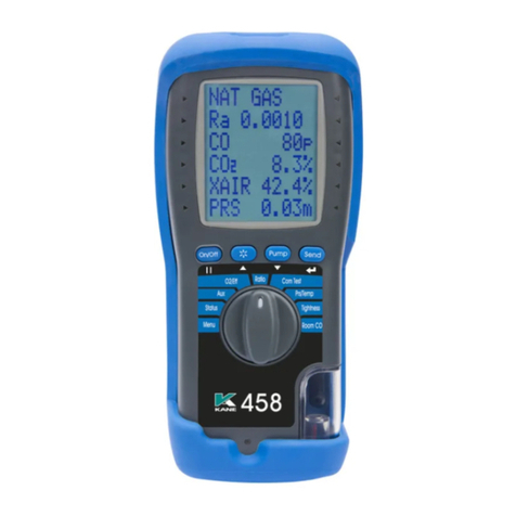
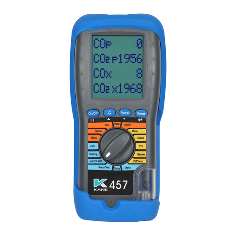
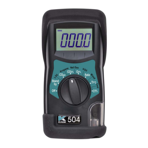
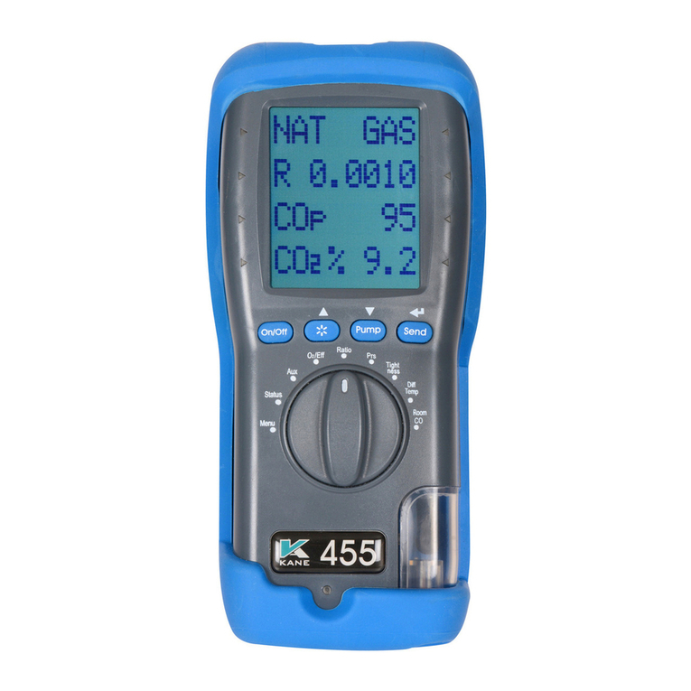
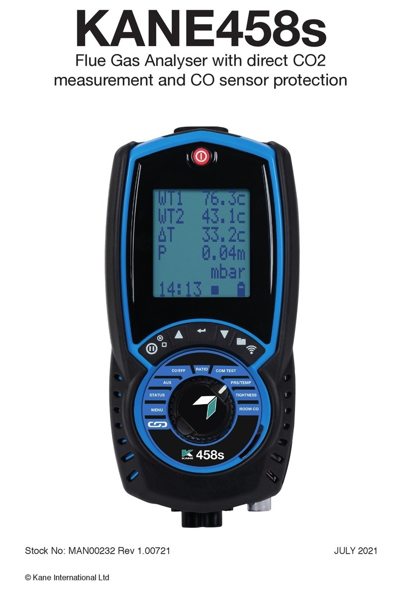
Kane KANE458s User manual

KANE458s
Stock No: MAN00232 Rev: 1.01022 OCTOBER 2022
© Kane International Ltd
Flue Gas Analyser with direct CO2
Measurement and CO sensor protection
KANE LINK

CONTENTS Page No.
2 KANE458s MANUAL
2.1
2
1
3
2.3
2.2
4.2
4.1
4
4.5
4.4
4.3
6.1
6
5
6.3
6.2
ANALYSER AT A GLANCE 7-10
KANE458s OVERVIEW & KANE LINK 6
ANALYSER LAYOUT 8
KEYPAD & ROTARY DIAL 9
BACK OF ANALYSER & PROBE 10
BATTERIES 12
BATTERY TYPE 12
REPLACING BATTERIES 12
UPDATING TIME AND DATE 12
CHARGING NIMH BATTERIES 12
BATTERY DISPOSAL 12
FIRST TIME USE 13
GENERAL OPERATING PRINCIPLE 13
QUICK START & POWER ON 13
USER INTERFACE 13
STATUS 14
GENERAL SAFETY 11
3.1
3.2
FLUE GASES 11
PROTECTION AGAINST ELECTRIC SHOCK 11
6.4 STATUS BAR 14

6.8
6.7
7.1
6.9
KANE458s MANUAL 3
STATUS BAR ICON ZONE 16
STATUS BAR MENU OPTIONS 17
STANDARD OPTIONS 17
7USING MENU 17
MENU CHOICES 18-19
ANALYSER MEMORY 20
7.3
7.4 MEMORY OPTIONS 20
VIEWING STORED LOGS 21
7.5
7.6 SELECT LOG TYPE 21
7.7 SELECT LOG STORED 21
7.8 SELECT LOG OPTIONS 22
7.2 SEND, PRINT OR STORE A TEST 20
8MEASURING FLUE GASES 23
9HIGH CO LEVELS 24
VIEWING FLUE GASES USING ROTARY DIAL 24
10
AUX SCREEN 24
02 / EFF SCREEN 25
CO / CO2 SCREEN 25
6.6
6.5 STATUS BAR LAYOUT 15
STATUS BAR MESSAGE ZONE 15
6.5
IAQ SCREEN 25
10.1
10.2
10.3
10.4
2.1

11.2
11.1
11
11.3
12
12.1
14
13
15
15.1
15.3
15.2
TEMPERATURE & PRESSURE TESTING 26
TEMPERATURE & PRESSURE DISPLAY 26
PRESSURE MEASUREMENT 27
LARGE BORE TUBING ISSUES 27
TESTS 28
APPLIANCE COMMISSIONING TEST 28
12.2 ROOM CO & CO2 TESTS 29-31
12.3 LET-BY / TIGHTNESS TESTING & EDITING TIMES 32-33
PRINTING TO INFRARED PRINTER 34
SAMPLE PRINTOUTS 35
KANE LINK 37-38
WPCP2 PIPE CLAMP TEMPERATURE PROBES 37
DTHA2 ANEMOMETER 37
KANE79 PERSONAL & ROOM CO MONITOR 38
12.4 NAVIGATING STORED TESTS 33
14.1 SAMPLE SIMULTANEOUS ROOM CO TESTS WITH
KANE LINK CO MONITORS 36
15.4 TRANSFER DATA TO SMARTPHONE OR TABLET 39
16 MAINTENANCE 40
KANE458s MANUAL 4
16.2
16.1
FLUE GAS & TEMPERATURE PROBE 40
16.3
WATER TRAP, PARTICLE FILTER & WATER STOP
FILTER 40
BATTERY CHARGER & BATTERIES 41
16.4 SYSTEM LEAK TEST 41

KANE458s MANUAL 5
21
22
23
KANE CARE 46-49
COMBUSTION PROBE OPTIONS 50
KANE CARE 5 YEAR SERVICE PLAN 50
24 ASSESSORIES & CONSUMABLES 51
23 ANALYSER RECYCLING 52
24 THANK YOU 53
19
20
17
SPECIFICATION 43-44
EU DECLARATION OF CONFORMITY 45
COLD WEATHER PRECAUTIONS 42
18 WHERE TO SEND YOUR ANALYSER 42
20

KANE458s OVERVIEW & KANE LINK
Your KANE458s flue gas analyser measures:
• Carbon Monoxide (CO)
• Carbon Dioxide (CO2)
• Differential Pressure
• Differential Temperature
Depending on configuration it also measures or calculates:
• Oxygen (O2)
• Nitric Oxide (NO) & Oxides of nitrogen (NOx)
• CO/CO2 ratio
• Combustion Efficiency, loses & excess air
• Ambient Carbon Dioxide (CO2)
• Tightness, Let by, Commission & Room Co Tests
Your analyser has:
Protective rubber cover with magnets for hands-free operation
Flue probe with integral temperature sensor
Battery charger & 3 NiMH batteries.
Low flow detection to power off pump if water enters analyser
Large 6 line display showing data & test results - Display bottom line also
highlights analyser status.
Test reports to optional infrared printer or wirelessly to KANE LIVE App.
45 log memory for any combination of Combustion, AUX, Temperature &
Pressure tests.
Memory for 25 Tightness Tests, 25 Commissioning tests & 14 ROOM CO
tests - see page 19
2 lines of 24 characters to personalise with your details.
KANE LINK
Wirelessly connect optional KANE LINK devices to your analyser.
When powered on, they replace or add measurements your analyser makes.
See page 36 to manage optional KANE LINK devices.
6 KANE458s MANUAL
1

ANALYSER AT A GLANCE
KANE458s MANUAL 7
2

ANALYSER LAYOUT
Power
Keypad
Rotary Dial
Water trap &
particle filter
8 KANE458s MANUAL
Flue Gas Probe Temperature
Plug -
Connect to Temperature T1
Narrow (+ve) pin must be
on right side
Red connector
Connect to Flue Gas Inlet
Flue probe hose
Battery
charger
Pressure port
P2 - Differential
Flue Gas
inlet
Water trap drain with
red plug
Pressure port P1
Ambient Temperature Socket T2
Differential
Flue Gas Temperature
Socket T1
2.1
6 line display
with backlight
Infrared printer emitter
Battery status
indicator

KEYPAD & ROTARY DIAL
Keypad
SYMBOL DESCRIPTION
PUMP Press to turn pump on or off
DATA HOLD - Short press to hold current data on screen - see status
bar section on page 14
NAVIGATE UP - Short press to scroll up
ENTER ENTER KEY - Use to select current option - also selects torch in some
dial positions
NAVIGATE DOWN - Short press to scroll down
STORED LOG - Long press to store data
SEND PRINT LOG - Short press to transfer a log - Analyser offers a
destination choice
KANE458s MANUAL 9
Rotary
Dial
2.2
SYMBOL DESCRIPTION
Add, Manage or Delete KANE LINK devices & App Settings
MENU Manage Analyser Settings
STATUS View Analyser Status
AUX Personalise Analyser Display
O2 / EFF Appliance Efficiency Test
RATIO Appliance CO / CO2 Ratio Test
IAQ Ambient CO & CO2 Test
COM TEST Domestic Gas Boiler Commissioning Test
TEMP / PRS Temperature & Pressure Test
TIGHTNESS Let-by & Tightness Test
ROOM CO Migration & Sweep Test

10 KANE458s MANUAL
Flue
Temperature
Probe
Flue Gas
Probe
Depth stop
cone
Flue Gas
Probe
hose
Thermocouple
wire
Water trap
drain with
red plug
Magnets x 2
Gas
exhaust
2.3 ANALYSER BACK & PROBE

Your analyser extracts combustion gases that are toxic in relativity low
concentrations.
These gases are exhausted from the bottom of the analyser.
This analyser must only be used in well-ventilated locations by
trained and competent persons after considering all potential hazards.
Portable gas detectors should conduct “bump” tests before relying
on units to verify atmospheres are free from hazards.
A “bump” test is a way to check an instrument works within acceptable
limits by briefly exposing it to known gas mixtures to change output
of all sensors present.
NOTE: This is different from calibration where your analyser is exposed
to known gas mixtures but allowed to settle to a steady figure with
readings adjusted to the gas concentration of the test gas.
This analyser is designed as Class III equipment and should only be
connected to SELV circuits. The battery charger is designated as:
• Class II equipment
• Installation category II
• Pollution degree 2
• Indoor use only
• Altitude to 2000m
• Ambient temperature 0°C -40°C
• Maximum relative humidity 80% for temperatures up to 31°C
decreasing linearly to 50%RH at 40°C
• Mains supply fluctuations not to exceed 10% of the nominal voltage
KANE458s MANUAL 11
3GENERAL SAFETY
3.1 FLUE GASES
3.2 PROTECTION AGAINST ELECTRIC SHOCK
(IN ACCORDANCE WITHN 61010-1:2010):
SAFETY WARNING

BATTERY TYPE
Your analyser uses rechargeable Nickel Material Hydride (NiMH)
batteries.- Using other battery types may void your analyser warranty.
WARNING
You can use Alkaline batteries but do not charge analyser when fitted.
Do not mix NiMH cells with different capacities or from different
manufacturers - All batteries must be identical.
REPLACING BATTERIES
Turn over analyser & remove protective rubber cover to find battery
compartment.
Fit 3 NiMH “AA” rechargeable batteries ensuring correct battery polarity.
Replace battery cover & protective rubber cover.
UPDATING TIME AND DATE
Reset analyser time & date after changing batteries.
CHARGING NiMH BATTERIES
Your analyser uses a standard Micro USB connector - For best results
power off before connecting charger. Charging indicator illuminates then
flashes off when charging is complete.
First charge for 8 hours - Thereafter NiMH batteries can be topped up any
time, even for short periods
If batteries discharge and analyser enters low power shutdown, 1 hour
charge provides approx. 2 hours continuous use.
BATTERY DISPOSAL
Always dispose of depleted batteries using approved disposal methods that
protect the environment.
12 KANE458s MANUAL
4BATTERIES
4.1
4.2
4.3
4.4
4.5

Charge your analyser batteries for 8 hours - an overnight charge should be
sufficient for an average 8-hour day.
Take time to read this manual fully and be aware your analyser configuration
may not support all features explained in this manual.
Before using your analyser ensure it is setup for your requirements.
NOTE: Your analyser STATUS bar displays current time, date and
battery status - Time & date can only be changed with no stored logs in
memory to protect integrity of stored logs.
GENERAL OPERATING PRINCIPLE
Using your analyser is simple with the rotary dial and user interface.
Most tests can be made with little user activity.
Your analyser status bar offers options based on tasks you are
performing and displays useful information and messages.
QUICK START & POWER ON
Your analyser has two power on modes: Quick Start & Combustion analysis.
For quick start, rotate dial to any position not starting combustion analysis e.g:
MENU, STATUS, TEMP/PRS.
Your analyser will give quick access to non gas measurement functions.
Rotating dial to a position to measure gas starts auto zero calibration.
Power on analyser with dial set to any position starting combustion analysis
starts auto zero calibration.
Power on analyser by pressing button for 2 seconds.
NOTE: Always power on analyser in fresh outdoor air.
USER INTERFACE
Your analyser displays 5 lines of tests & a status bar.
The display backlight power on with each button press then powers off after 10
seconds.
Navigate through options and menu choices via or & ENTER.
KANE458s MANUAL 13
5FIRST TIME USE
6
6.1
6.2

Rotate dial to STATUS to view:
Status bar shows analyser status & offers options based on your settings
Navigate through status bar options via or when status bar on display.
14 KANE458s MANUAL
Status bar
Current fuel selection - use status bar
menu to change fuel selection
Current ambient temperature
Current atmospheric pressure (mbar)
No. of days until next calibration due
Status bar
6.3
6.4
STATUS
STATUS BAR

Status bar has 2 zones: MESSAGE & ICONS
STATUS BAR MESSAGE ZONE
CLOCK FUCTION
DATA HOLD
FUNCTION
CALIBRATION DUE
WARNING MESSAGE
AIR PURGE
“SNOOZE”
TIMER
LOW BATTERY
WARNING
MESSAGE
Displays current time
Display alternates
between hold symbol &
time stamp of held data
Display alternates
between calibration due
& current time
Display alternates between
air purge delay symbol &
current time
Display alternates
between BAT symbol &
current time
KANE458s MANUAL 15
STATUS BAR LAYOUT
6.5
6.6

STATUS BAR ICON ZONE
Icons give sample status information:
PUMP
LOGGED DATA
SENDING DATA
BATTERY
Pump status On or Off
Analyser has logged /
stored data
Data being sent to
App or Printer
Battery status indication
16 KANE458s MANUAL
6.7

STATUS BAR MENU OPTIONS
Status Bar offers contextual menu options based on your screen.
STANDARD OPTIONS
USING MENU
Rotate dial to MENU to change analyser settings to your requirements.
Navigate through MENU using or & ENTER
As you navigate up or down items move up or down screen returning to the
beginning.
To exit MENU rotate dial to any position but note unsaved changes will be
lost.
Date - Displays current date
Displays selected fuel type - To change,
long press ENTER to display
selection Indicators
Press or to select fuel then press
ENTER
Menu option to edit
KANE458s MANUAL 17
Rotate dial to AUX to change AUX
screen then long press ENTER until
cursor flashes
6.9
6.10
7

18 KANE458s MANUAL
7.1
MENU ITEM MENU TEXT OPTIONS / COMMENTS
TIME
TIME
Select TIME to set analyser time - Press
ENTER then use or & ENTER to set
correct HH:MM:SS
DATE
DATE
Select DATE to set analyser date - Press
ENTER then use or & ENTER to set
To set correct DD:MM:YY
HEADER
HEADER
Select HEADER to personalise 2 lines of 24
characters - Press ENTER, select line to edit
pressing & to select LINE 1 or LINE 2.
Use & to select correct character then
press ENTER
To set HEADER via KANE LIVE app, select
CONTROLS on app, select ANALYSER
HEADERS, select LINE to edit
Select SAVE to set header
PRINTER TYPE
PRINTER TYPE
Select IR PRINTER to set infrared printer -
press ENTER then use or & ENTER to
select KMIRP or IRP-2/3
GAS SCALE
GAS SCALE
Select GAS UNIT by pressing ENTER then
select gas scale ppm, mg/m3 or mg/kWh
using or & ENTER
O2 REF
O2 REF
Select O2 REF to set % reference O2 for
each gas measured - Press ENTER then
select gas using & then ENTER.
Change % reference O2 by pressing or
then press ENTER to confirm
MENU CHOICES

CONTINUED MENU CHOICES
KANE458s MANUAL 19
NOX CALC
NOX CALC
(If NO sensor fitted)
Set REFERENCE NOx to percentage
required or defined by local regulations.
It is typically assumed boiler emissions of
NOx = NO + 5% NO2
If required, you can calculate NOx from 3
options - SUM, NO or NO2.
SUM adds NO & NO2 if both sensors are
fitted.
NO calculates NOx from NO, if fitted, where
NOx = NO x 1.1
NO2 calculates NOx from NO2 only, if fitted,
where NOx = NO2 x 2.05.
Use or to select then press ENTER
LOGS LOGS View current memory usage & stored logs
EFF
EFF
Select EFF to set efficiency scale by
pressing ENTER.
Select NETT or GROSS using & , then
press ENTER to confirm
Considering calculation automatically
selected based on selected fuel
UTIL
UTIL
Select UTIL to access utility menu - Press
ENTER then or & ENTER to select
from:
INFO - Shows Analyser firmware, wireless
firmware & date next calibration due
LEAK - Performs system leak test following
onscreen instructions
B’LIGHT - Selects time backlight is on from
15 to 300 seconds using or & ENTER
to confirm
NOTE: Extending backlight time reduces
analyser battery life
CODE
CODE Password protected for authorised service
agents only - Default to 000000

SEND, PRINT OR STORE A TEST
Short press SEND to send a test to your optional KANE-IRP3 printer or
KANE LIVE App.
Long press SEND for 2 seconds to store a test, called log.
Your analyser has a shared memory system to store up to 45 tests, called
logs.
For example: combustion logs or any combination of combustion, Aux &
Pressure / Temperature logs up to 45.
Your analyser also stores up to 25 tightness tests, 25 commission tests and
14 room tests called logs - view when you rotate dial to relevant test.
A logged data icon displays when your analyser has stored a test - see page
16.
To view memory rotate dial to MENU then select LOGS using or &
ENTER to display.
20 KANE458s MANUAL
7.3
No. of stored Combustion logs
No. of stored Pressure / Temperature
Total memory used
Menu options
No. of stored Auxiliary logs
View stored logs if available
Return to main menu
MEMORY OPTIONS
Delete all stored logs if available - to
delete long press ENTER
7.4
ANALYSER MEMORY
7.2
Other manuals for KANE458s
2
Table of contents
Other Kane Measuring Instrument manuals
Popular Measuring Instrument manuals by other brands

WB Johnson Instruments
WB Johnson Instruments AM-801 Operation & maintenance manual

Vega
Vega VEGABAR 81 operating instructions

Hanna Instruments
Hanna Instruments HI 83540 instruction manual

Moeller
Moeller Xcomfort CTEU-02/01 Assembly instructions

Landis+Gyr
Landis+Gyr ULTRAHEAT XS operating instructions

Buhler
Buhler SM-6 Installation and operation instructions