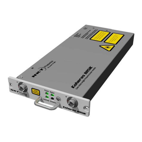
NKT Photonics MIKRO C15 User manual

Item: 800-610-01
Customer Revision: 1.3
NKTP Revision: 2.0
Release Date: 03-2022
Koheras MIKRO
PRODUCT GUIDE
Low Noise Single Frequency Laser Module

PRODUCT GUIDE
This guide includes the following NKT Photonics Lasers:
Koheras MIKRO
Low Noise Single Frequency Laser Module
Previously referred to as the Koheras BASIK MIKRO.
W-10456

3
GUIDE OVERVIEW
This product guide is intended to provide functional, operational and installation
information for the Koheras MIKRO laser modules. The guide is divided into three
sections:
• Koheras MIKRO Description - introduces the laser, its functionality,
interfaces and chassis variants.
• Operating the laser – provides information and procedures on how to
connect and configure communications with the laser and manage its
operation.
• Installing the laser – includes the details on how to install the laser chassis
variants and connect optional interfaces.
Warning: Do not operate the laser before first reading and understanding all
warnings, cautions and handling information stated within the document:
Koheras MIKRO Safety, Handling and Regulatory Information
Note: The paper copy of this guide is included with your laser however it can also
be downloaded from:
https://www.nktphotonics.com/lasers-fibers/support/product-manuals/
Terminology The guide may refer to the Koheras MIKRO modules as “the laser”. In specific
cases where a distinction is required, the guide will use the actual laser model
names or simply as “the module”.
Target audience This guide is for technical personnel involved in the selection, planning and
deployment of lasers in laboratory and industrial settings. The guide assumes a
reasonable knowledge level of lasers, photonic principles and electrical interface
connectivity.
Chapters inside This guide includes the following chapters:
• Chapter I “Laser description” — Describes the laser including its general
operational principles, management and interfaces.
• Chapter 2 “Communicating with the Laser” — Provides information and
procedures on how to setup a PC with the laser’s management software and
connect it to the laser.
• Chapter 3 “Turning ON the Laser” — Contains procedures on how to safely
turn the laser emissions on and off using the management software.
• Chapter 4 “Using CONTROL” — Includes descriptions and procedures of all
other GUI menu and panel items.

4
• Chapter 5 “Software Development Kit” — Includes descriptions and
procedures for certain key settings that can be configured using the SDK.
• Chapter 6 “Mechanical Installation” — Includes information and procedures
on how to correctly install the laser chassis. Procedures within this chapter
focus on providing adequate temperature regulation.
• Chapter 7 “Connecting the laser” — This chapter provides the information on
how to physically connect the safety interlock, power, the optical collimator,
and the optional interfaces.
• Appendices — The guide includes multiple appendices including laser
specifications, support contact details, accessory descriptions, a
configuration ID cross-reference and miscellaneous procedures supporting
the laser operation and installation.
Added information
and safety notices
Lasers are highly dangerous devices that can cause serious injury and property
damage. This guide use the following symbols to either highlight important safety
information or provide further information in relation to a specific topic.
Note: Highlights additional information related to the associated topic and/or pro-
vides links or the name of the NKT guides describing the additional information.
Caution: Alerts you to a potential hazard that could cause loss of data, or damage
the system or equipment.
Warning: The laser safety warning alerts you to potential serious injury that may
be caused when using the laser.
Revision This section records the document revision details.
Date Revision Changes
2019-09 1.0 First release - documents rewritten and overhauled from earlier releases.
2020-01 1.1 Added Appendix F - Configuration IDs. Configuration ID description and
cross-reference for standard configuration IDs.
2020-01 1.2 Updated information regarding implementing the interlock with a safety
door switch. The following sections are affected:
•“Main electrical interface” on page 26
•“Connecting CONTROL to the laser” on page 32
•“Connecting the SDK GUI to the laser” on page 33
•“Connecting the safety interlock” on page 61
•“Main electrical interface” on page 71
•“Interlock” on page 79
2021-01 1.3 Updated support contact information in Appendix B.
2021-03 1.4 Errors in text edited or removed.
2021-03 1.0 Revision rolled back to 1.0 due to internal system requirements.

5
2022-01 1.1 Null change
2022-02 1.2 •Product name changed to Koheras MIKRO from Koheras BASIK
MIKRO.
•Added scales drop down selection description in Procedure 3 on
page 56.
•Added power scale drop down selection of wavelength or offset to
section “Power mode” on page 76.
•Added Figure 33 on page 71 showing the pinout of the main
electrical interface.
•Updated Procedure 9 on page 73 to Windows 10.
•Minor grammar corrections and improvements in language clarity.
•Some figures have also been modified for clarity.
2022-03 1.3 Updated with the following:
•Removed the misapplied serial monitor description and replaced it
“Device Monitor” on page 51.
Date Revision Changes

6

6
CONTENTS
Guide Overview ............................................................................................... 3
Terminology ......................................................................................... 3
CONTENTS .................................................................................................... 6
TABLES ........................................................................................................ 11
FIGURES ...................................................................................................... 13
PROCEDURES ............................................................................................ 15
Section 1 MIKRO DESCRIPTION 17
1 Laser description ........................................................................................... 19
Theory of operation ............................................................................ 19
Module variants .......................................................................................20
Configuration ID ................................................................................. 20
Center wavelength ............................................................................. 20
Tuning types ...................................................................................... 20
Laser features ......................................................................................... 20
Thermal tuning ................................................................................... 20
Fast wavelength modulation .............................................................. 21
Operating mode ................................................................................. 21
Auto-start ........................................................................................... 22
Emission delay ................................................................................... 22
Shutdown delay ................................................................................. 22
High temperature shutdown ............................................................... 22
Power verification ............................................................................... 23
Miscellaneous ......................................................................................... 23
Power supply ..................................................................................... 23
Safety ................................................................................................. 23
Accessories ........................................................................................ 23
Optical interface ......................................................................................24

7
Electrical Interfaces .................................................................................25
Main electrical interface ..................................................................... 26
Fast wavelength modulation input ..................................................... 26
Laser Control ..........................................................................................26
User interface .................................................................................... 26
Status LEDs ............................................................................................27
Module labels .........................................................................................28
Section 2 OPERATING THE LASER 29
2 Communicating with the Laser ...................................................................... 31
CONTROL software ...............................................................................31
Installing the software ........................................................................ 31
Software Development Kit ......................................................................31
Generic User Interface ....................................................................... 31
Connecting CONTROL to the laser ........................................................ 32
Connecting the SDK GUI to the laser .....................................................33
3 Turning ON the Laser ................................................................................... 35
Safety .....................................................................................................35
Preparation ............................................................................................. 35
Controlling laser emission .......................................................................36
Turning On the laser .......................................................................... 36
4 Using CONTROL .......................................................................................... 39
CONTROL overview ............................................................................... 39
Relocating panels .............................................................................. 40
Toggling panels visible ...................................................................... 41
Connecting to the laser ...................................................................... 41
Status panel............................................................................................. 43
Status indicators ................................................................................ 43
System info ........................................................................................ 43
Emission button ................................................................................. 44
Settings .............................................................................................. 44

8
CONTROL menu items ...........................................................................46
Key Updater tool ................................................................................ 46
Log Downloader ................................................................................. 47
Extensions Overview ......................................................................... 48
CONTROL – Control panel......................................................................50
Power mode ....................................................................................... 50
Current mode ..................................................................................... 50
Device Monitor.........................................................................................51
Application log ........................................................................................52
5 Software Development Kit ............................................................................. 53
Tuning the wavelength ...........................................................................53
Setting the operating mode .....................................................................54
Auto start ................................................................................................54
Setting the emission delay ......................................................................55
Section 3 INSTALLING THE LASER 57
6 Mechanical Installation .................................................................................. 59
General ................................................................................................... 59
Heat dissipation ................................................................................. 59
Installation method ..................................................................................60
Operating and storage environment .................................................. 60
7 Connecting the laser ..................................................................................... 61
Connecting the safety interlock ..............................................................61
Interlock operation ............................................................................. 61
Connecting an interlock switch .......................................................... 62
Connecting power....................................................................................63
Fast wavelength modulation input ..........................................................63
Capacitance ....................................................................................... 64
Slew rate ............................................................................................ 64
Connecting the optical output .................................................................64

9
Appendices
A Specifications ................................................................................................ 67
B Service and support Information ................................................................... 69
Servicing the laser .................................................................................. 69
Opening the module casing ............................................................... 69
WARRANTY VOID IF REMOVED Label ........................................... 69
Support contact details............................................................................70
Support website ................................................................................. 70
Online support web-page ................................................................... 70
Shipping address ............................................................................... 70
C Interface pin assignments ............................................................................. 71
Main electrical interface .......................................................................... 71
Fast wavelength modulation input ...........................................................72
D CONTROL installation .................................................................................. 73
Installing CONTROL ...............................................................................73
E RS-485 adapter ............................................................................................. 79
Main adapter ...................................................................................... 79
F Configuration ID ........................................................................................... 81
Module Configuration ID .................................................................... 81

11
TABLES
Table 1: MIKRO output specifications .............................................................. 20
Table 2: Recommended Power Modes ............................................................ 22
Table 3: Optical interface specifications .......................................................... 24
Table 4: Connectors ......................................................................................... 25
Table 5: Status LEDs........................................................................................ 27
Table 6: Module labels ..................................................................................... 28
Table 7: CONTROL panels and menu items.................................................... 39
Table 8: Device Monitor parameters ................................................................ 51
Table 9: Power adapter specifications.............................................................. 63
Table 10: Fast wavelength modulation specifications ...................................... 64
Table 11: Optical ............................................................................................. 67
Table 12: Mechanical dimensions ................................................................... 67
Table 13: Operating and storage environment ................................................ 67
Table 14: Electrical ........................................................................................... 68
Table 15: Safety and regulatory compliances .................................................. 68
Table 16: Main electrical interface pin assignment........................................... 71
Table 17: Fast Wavelength Modulation input ................................................... 72
Table 18: RS-485 adapter status LEDs............................................................ 80
Table 19: Standard MIKRO Configuration ID ................................................... 81

12

13
FIGURES
Figure 1: Working panel of the MIKRO ............................................................ 19
Figure 2: Frequency response using wavelength modulation ......................... 21
Figure 3: USB-RS485 adapter ......................................................................... 24
Figure 4: MIKRO equipped with fiber cord and FC/APC connector ................ 24
Figure 5: Front panel electrical connections .................................................... 25
Figure 6: Status LEDs ..................................................................................... 27
Figure 7: Top Panel Label Locations ............................................................... 28
Figure 8: GUI panel navigation ........................................................................ 39
Figure 9: Relocating panels within CONTROL ................................................ 40
Figure 10: Dragging panels outside the main window ..................................... 40
Figure 11: Toggling panel visibility .................................................................. 41
Figure 12: Welcome screen and connecting ................................................... 41
Figure 13: Connect button ............................................................................... 42
Figure 14: Status panel ................................................................................... 43
Figure 15: Settings .......................................................................................... 44
Figure 16: Controls displayed in current mode ................................................ 45
Figure 17: Enabling the auto-start function ...................................................... 45
Figure 18: View setting .................................................................................... 45
Figure 19: Menu Items ..................................................................................... 46
Figure 20: Extensions Overview ...................................................................... 49
Figure 21: Operating mode set to power ......................................................... 50
Figure 22: Operating Mode set to Power ......................................................... 50
Figure 23: Serial Monitor ................................................................................. 52
Figure 24: Setting Register 0x2A – Wavelength .............................................. 53
Figure 25: Setting register 0x31 – setup bits (operating mode) ....................... 54
Figure 26: Setting Register 0x31 – Setup bits (Auto-start function) ................ 54
Figure 27: Setting Register 0x3A – Emission delay ........................................ 55
Figure 28: Mounting the laser .......................................................................... 60

14
Figure 29: RS-485 adapter connected to a door switch (open position) ......... 62
Figure 30: Power supply .................................................................................. 63
Figure 31: Mechanical dimensions .................................................................. 68
Figure 32: Warranty seal ................................................................................. 69
Figure 33: Main electrical interface PIN layoutl ............................................... 71
Figure 34: RS-485 adapter .............................................................................. 80
Figure 35: How to read the configuration ID .................................................... 81
white

15
PROCEDURES
Procedure 1: Connecting CONTROL to the laser ........................................... 32
Procedure 2: Connecting the Generic User Interface to the laser................... 34
Procedure 3: Enable emission using CONTROL ............................................ 36
Procedure 4: Enable emission using the SDK Generic User Interface ........... 37
Procedure 5: Relocating panels ...................................................................... 40
Procedure 6: Using the Key Updater tool........................................................ 46
Procedure 7: Using the Log Downloader......................................................... 47
Procedure 8: Connecting the door interlock circuit.......................................... 62
Procedure 9: Installing CONTROL ................................................................... 73

16

17
SECTION 1
MIKRO DESCRIPTION
This section provides a description of the laser and its chassis types. It includes
the following topics:
•“Laser description” on page 19
•“Module variants” on page 20
•“Laser features” on page 20
•“Miscellaneous” on page 23
•“Optical interface” on page 24
•“Electrical Interfaces” on page 25
•“Laser Control” on page 26
•“Status LEDs” on page 27
•“Module labels” on page 28

18

19
1 Laser description
The Koheras MIKRO is an industrial single frequency fiber laser housed within a
micro-casing. Further, the laser and its micro-casing (referred to as a module) is
designed for integration with industrial applications where its built-in laser control
circuits can continuously monitor the laser’s performance. Using these
monitoring circuits, the laser supports applications that demand ultra-low noise,
high wavelength stability and ultra-stable single frequency operation unaffected
by mode hops.
Figure 1 Working panel of the MIKRO
The laser is designed with distributed feedback fiber laser technology and center
wavelengths that can be specified from 1535 to 1580 nm. The laser also supports
a wide tuning range of approximately 1 nm from the specified center wavelength.
Tuning is accomplished either manually through thermal tuning or using an
external signal applied at the laser’s fast wavelength modulation input port. A
varying external signal applied to the port, modulates the output wavelength.
Modulating the output wavelength can obtain improved stabilization when
compared with the free-running wavelength specification.
The standard output of the laser utilizes either standard single mode fiber or
optional polarization-maintaining fiber to improve the linear characteristics.
Improved polarization linearity is usually required when the laser output is either
externally modulated or frequency converted.
Theory of operation The Koheras MIKRO is a fiber laser that uses a fiber Bragg grating cavity to
produce an output beam operating in single mode. The center wavelength of the
laser is configurable using either thermal substrate control or optional Piezo
components. Due to the special Bragg grating, the single mode operation is
constantly maintained and is stable over the entire operating frequency band of
the laser.

Module variants
20
Module variants
Koheras MIKRO modules are available in two variants: the E15 and C15 modules.
The modules are classified by their phase noise, intensity and power level.
Table 1 lists the technical differences between the two variants.
Table 1 MIKRO output specifications
Configuration ID MIKRO modules are defined by their configuration ID which includes the options.
Refer to Appendix F for a list of Koheras MIKRO configuration IDs.
Center wavelength The center wavelength of a standard MIKRO laser is set to 1550.12 nm1. On
ordering, the lasers can also be modified at the factory to other center
wavelengths from 1535 to 1580 nm.
Tuning types Both module variants can be further specified with different tuning options. The
options include narrow and wide thermal tuning for coarse adjustment and Piezo
tuning for finer adjustment. Tuning options are specified when the laser is
ordered from the factory.
Piezo tuning
The standard Piezo tuning option allows the laser to implement fine fast
wavelength modulation. For further information see “Fast wavelength
modulation” on page 21).
Thermal tuning options
Thermal tuning options available are:
• Narrow thermal tuning – provides narrow thermal tuning suitable for
systems where a wide tuning range is not required but vibration immunity is
vital.
• Wide thermal tuning – provides a wider thermal tuning range at the expense
of reduced immunity to vibration and acoustic pickup.
Laser features
Thermal tuning The wavelength of the lasers can be controlled using a thermal tuning technique
that changes the temperature of the laser’s fiber. The fiber laser is mounted
under tension on a substrate. When the temperature of the substrate changes,
Module Type Maximum Output Power Phase Noise RIN
C15 10 mW Low Ultra-low
E15 40 mW Ultra-low Low
1. ITU DWDM C-BAND Channel 34
2
This manual suits for next models
1
Table of contents
Other NKT Photonics Measuring Instrument manuals

NKT Photonics
NKT Photonics SuperK FIANIUM User manual
NKT Photonics
NKT Photonics Koheras HARMONIK User manual
NKT Photonics
NKT Photonics Koheras ACOUSTIK User manual
NKT Photonics
NKT Photonics SuperK COMPACT User manual
NKT Photonics
NKT Photonics SuperK FIANIUM FIU-6 User manual

NKT Photonics
NKT Photonics PILAS User manual
NKT Photonics
NKT Photonics SuperK EVO User manual
NKT Photonics
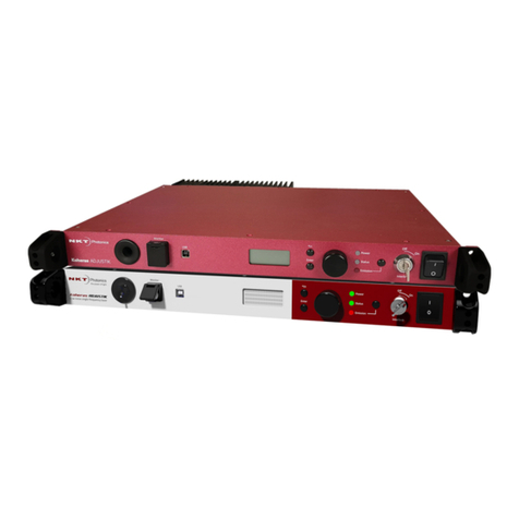
NKT Photonics Koheras ADJUSTIK HP User manual

NKT Photonics
NKT Photonics Koheras ADJUSTIK User manual
NKT Photonics
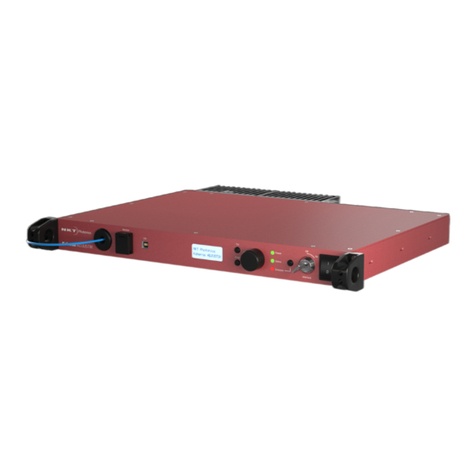
NKT Photonics ADJUSTIK User manual

