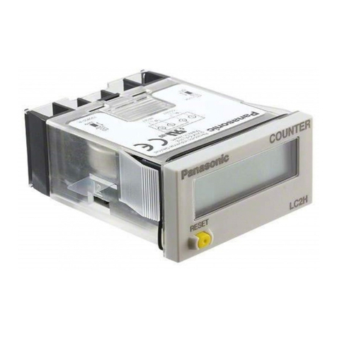
NLS PC-40 User manual

Non-Linear Systems
PC-40 4-Digit
Up/Down Event
Counter
INTRODUCTION
The PC-40 Digital Panel Counter is a solid-
state, 4 digit, up/down event counter or
totalizer. It is designed to provide totalizing
capability from either contact closures or
logic-level signals. The count, reset and
latch inputs are conditioned to provide high
noise immunity. It is a highly reliable
component which can be used to replace
electromechanical types.
The PC-40 is designed to operate with a
+5VDC ±5% power supply. See Figure 1 for
a typical +5V power supply circuit for
operation from 120VAC.
Figure 1. Typical Power Supply
SPECIFICATIONS
COUNT RATE:
Logic Level: * 0 to 1,000,000/sec
Contact Closure: 0 to 50/sec
*This speed is achieved by removal of internal capacitors which
normally provide filtering of contact bounce.
INPUT SIGNAL AMPLITUDE:
Logic Level: +3.0V to +15V
Contact Closure: Ground for count
DISPLAY: 0.3" high LED, 4 Digits
OVERFLOW INDICATION:
Blinking Decimals (up only)
POWER: +5VDC ±5% @ 0.75W
OPERATING TEMP.: 0°to 50°C
WEIGHT: 4oz (113 g)
DECIMAL LOCATION: Positioned by
jumper on connector to any one of 4
locations.
BCD OUTPUT: Multiplexed, bit parallel
character serial at approximately a 600 Hz
rate.
DECIMAL POINT OUTPUT:
Multiplexed, pulse occurs on decimal point
common at the same time as the pulse for
the digit to the right of the decimal occurs.
ZERO SUPPRESSION: Ground to
inhibit
BLANKING/DISPLAY INHIBIT: For on or
off intensity control, connect to +5VDC
through a potentiometer (0-1KΩ) and switch
(if desired) maximum current is 150mA.
RESET: Negative going to low (GND) from
logic level source on switch closure to GND.
CARRY: At 9999 count, an output is
provided which goes positive (true). The
output goes to zero (low) at the next pulse
input to the counter. This occurs once each
10,000 pulses at the input. Designed for use
when cascading counters.
LATCH ENABLE: (For counts to 9999)
Open holds reading on counter at the time of
opening. Ground returns display to count at
the time of grounding (total since last reset).
OPERATING PRINCIPLES
INPUT CIRCUIT: The input circuit contains
an amplifier-filter to permit a contact closure
to be counted as a pulse input even if
contact bounce is present. If high speed
operation (above 50 per second) is desired,
up to 1,000,000 per second, internal filter
capacitors must be removed.
Figure 2. Simplified Block Diagram
COUNTER: The counter is a single
integrated circuit which is capable of
counting at a 1 MHz rate to a total of 9999.
The counter provides a carry output for
cascading counter for greater range. The
counter can be reset by a logic-level signal
or a contact-closure.
LATCH: The latch is externally controlled to
hold and display the total count when the
latches are enabled. This count will continue
to be displayed until the latch enable is
removed. Release of the latch enable results
in the latches and display being updated to
the then total count on the counter. From the
latch circuits, multiplexed BCD data is
available for the four decimal digits and the
decimal point. The multiplex rate is
approximately 600 HZ. Four strobe lines are
sequentially energized to tell which decimal
digit is being output on the four BCD data
lines. The sequence begins with the most
significant digit and proceeds to the least
significant digit. This sequence is repeated
at a rate of approximately 150Hz. The data
output is the same as that presented in the
display.
DISPLAY: The display may be used on or
off as desired. Further, it permits control of
the intensity of the display by using an
external potentiometer.
The leading zeros may be suppressed by
means of a special input; the counter will not
suppress to the decimal point selected. At
all zeros (0000), the display is blank.
INSTALLATION
Mount the PC-40 as follows:
1. Cut a hole in panel (figures 3 and 4).
2. Slide trim plate over PC-40 housing,
facing beveled edge of trim plate forward.
3. Insert PC-40 through the cutout in the
panel from the front of the panel.
4. Fit mounting clips (2) into the slots at the
sides of the meter. The foot of the clip
should face forward.
5. Thread the screws (2) into clips and
tighten the screws against the rear
surface of the panel.
Panel Cutout
w /Trim Plate
Center Line
w ithout Trim
Pla t e
Center Line
w /Trim Plate
Cutout For Multiple
Mounting w ithout Trim
Pla t e
A2 17/32
B31/32
C15/16 1 3/16 min
D3 1/8 min 3 1/8 min
ENumber of units x 15/16
Figure 3.Mounting Data
Figure 4. Outline Drawing

CONNECTOR PIN WIRING
The mating connector, if purchased,
should be NLS part # N39-282.
Connection to PC-40 is as follows:
Lower Contacts A Upper Contacts B
Carry Output 1110°Dec Pt.
Zero Suppress 2210¹Select
Reset 3310²& Data
N/C 4410³Strobe
N/C 55Latch Enable
MUX "1" 66N/C
BCD "2" 77N/C
Data "4" 88 Up/Down
Out "8" 99N/C
Count Input 10 10 Up/Down
Blank/Intensity 11 11 N/C
Overflow Out 12 12 N/C
Decimal Com. 13 13 N/C
SIG LO & 14 14 +5VDC
COMMON 15 15 POWER
OPERATION
POWER SUPPLY: Connect negative side
of power supply (Gnd) to pins A14 and A15
of connector and the positive side (+5VDC ±
5%) to pins B14 and B15. Even though the
current requirements of the PC-40 are low
(150 mA maximum @ 5VDC), redundant
contacts are used to enhance the reliability
of the connection.
COUNT INPUT: Connect signal input to
pins A10 and A14 or A15. Signal LO should
go to A14 or A15 and Signal HI should go to
pin A10. Input impedance is 100 KΩ.
Count Up: To count up connect pin
B10 to +5VDC
& B8 to A1
Count Down: To count down connect pin
B10 to Ground
& B8 to Ground
The PC-40 counts a pulse during the
positive-going part of the pulse or when a
contact made to ground is closed. Using
pulse or contact-closure inputs, the
maximum input rate is 50 per second. The
input signal may vary from zero to +3 - +15
volts in amplitude. When using voltage level
input with no contact bounce, the PC-40 will
operate at speeds up to 1,000,000 per
second. To achieve this speed, capacitors
C1, C2 and C3 must be removed from the
main board assembly.
To remove the capacitors, perform the
following steps:
1. Insert the blade of a small screwdriver or
pen knife between case and rear cover,
midway on case above printed circuit
connector, and pry gently outward.
Remove Cover.
2. Slide counter assembly from case.
Observe that red filter is now a loose
piece and will
be required for reassembly.
3. C1, C2 and C3 are the rear most three
capacitors on the main board assembly.
Unsolder leads and remove capacitors.
4. Reassemble meter.
RESET: A negative going pulse or a
contact closure to ground will cause a reset
of the counter. If a pulse is used the duration
must be at least 20 mSec, or with filter
removed at least 1 µSec.
DECIMAL POINT AND DATA
STROBE: If a decimal point is desired,
jumper between pin A13 and pins B1, B2,
B3 or B4 depending upon which decimal
point is to be illuminated. If a decimal point
is not desired, jumper pin A13 to pin B14.
Decimal Location . X . X . X . X
Pin Number B4 B3 B2 B1
As a data strobe, the true state is low. When
one of the four strobe lines is low, it means
that the four multiplexed BCD data output
lines are presenting the BCD code as an
output for the decade indicated by that
strobe line.
BCD OUTPUTS: The outputs of the MUX
BCD data output lines, pins A6, A7, A8 and
A9, are the 1-2-4-8 BCD bits for the four
digits. True is a high state. The decimal point
and data strobe lines described above are
used to decode the multiplexed data output.
The decimal point data output is obtained by
connection to the decimal point data is
decoded with the data strobe lines. For the
decimal point location, data output true is
low. An overflow indication is provided at pin
A12: true is high.
The MUX BCD outputs are as follows:
(nominal values)
BCD Data Decade Strobe
True-High True-Low
Frequency 600 Hz 150 Hz
Pulse Width 1500 µS 6000 µS
Voltage +5V +5V
Allowable CMOS 1 T²L
Loading (CMOS Preferred)
CARRY OUTPUT: On pin A1, an output
is provided which will permit the user to
cascade PC-40's. This output goes to +5
volts on the count of 9999. On the next pulse
input the voltage goes low. Allowable
loading is one CMOS load.
ZERO SUPPRESSION:If desired, the
zeros to the left of a significant digit can be
suppressed. to do so, leave pin A2 open. To
display all numbers, ground pin A2.
BLANKING/INTENSITY CONTROL: It
is possible to shut off the display or control
its intensity while operating in a count mode.
Pin A11 must be connected to +5VDC ±5%
for the display to be on. Placing a switch in
the line permits display on-off. A variable
resistor permits control if intensity.
Recommended resistance is 0 to 1 KΩ.
Maximum current is 150 mA @ 5 volts.
LATCH ENABLE: Connecting pin B5 to
ground causes the display to follow the
input. Each input pulse will be counted and
displayed. An open or no connection results
in the display of the number in the counter at
the time of the opening of the line.
Reconnection to ground causes an update
of the data to the then present number on
the counter. This function holds for total
counts to 9999.
CALIBRATION: Calibration is not
required; there are no adjustments in the
counter.
Specifications Subject to Change Without Notice
Thank you for choosing Non-Linear
Systems products. Should you have any
questions please call, fax or visit our
Website at nonlinearsystems.com
NON-LINEAR SYSTEMS
Originator of the Digital Voltmeter
San Diego, CA
Phone: (619) 521-2161
Fax: (619) 521-2169
Email: sales@nonlinearsystems.com
11-18

