Noaw 330/83 Troubleshooting guide
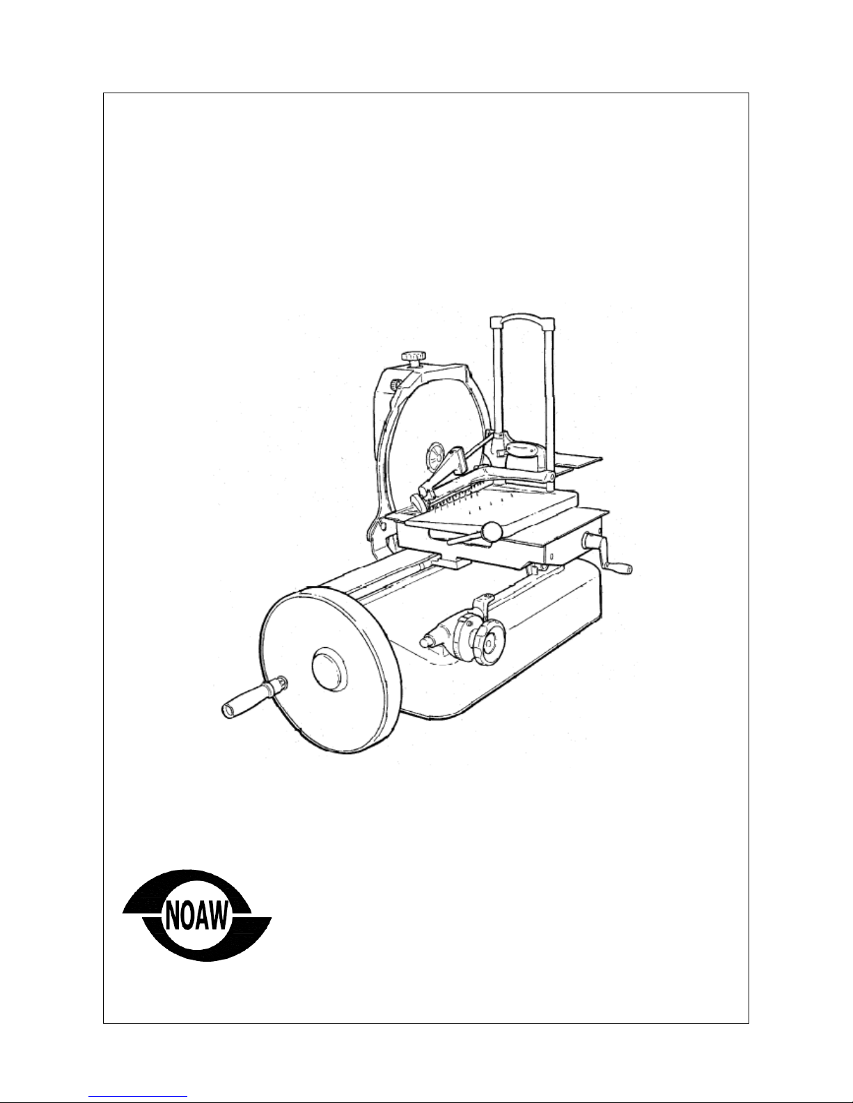
MANUAL FLYWHEEL
MANUAL FLYWHEEL MANUAL FLYWHEEL
MANUAL FLYWHEEL
SLICING MACHINE
SLICING MACHINESLICING MACHINE
SLICING MACHINE
Mod.
Mod. Mod.
Mod. 330/83
330/83 330/83
330/83 –
––
–
370/85
370/85370/85
370/85
Instruct on for use, nstallat on and ma ntenance
Instruct on for use, nstallat on and ma ntenanceInstruct on for use, nstallat on and ma ntenance
Instruct on for use, nstallat on and ma ntenance
Noaw s.r.l
V a Colombera, 27
21048 Solb ate Arno (VA) – Italy
Tel. 0331.219.723 - Fax 0331.216.197
E-ma l: noaw@noaw. t
http://www.noaw. t - www.noawsrl.com

Installation, use and maintenance
1
LIST OF CONTENTS
LIST OF CONTENTSLIST OF CONTENTS
LIST OF CONTENTS
Pag
PagPag
Page
ee
e
1. INTRODUCTION
1. INTRODUCTION1. INTRODUCTION
1. INTRODUCTION............................................................................................................................................................ 2
1.
1.1.
1.1 PURPOSE OF THE MANUAL
1 PURPOSE OF THE MANUAL1 PURPOSE OF THE MANUAL
1 PURPOSE OF THE MANUAL ................................................................................................................................. 2
1.2 KEEPING THE MANUAL
1.2 KEEPING THE MANUAL1.2 KEEPING THE MANUAL
1.2 KEEPING THE MANUAL........................................................................................................................................ 2
1.3 USE OF THE MACHINE
1.3 USE OF THE MACHINE1.3 USE OF THE MACHINE
1.3 USE OF THE MACHINE.......................................................................................................................................... 2
2. GENERAL INFORMATION
2. GENERAL INFORMATION2. GENERAL INFORMATION
2. GENERAL INFORMATION............................................................................................................................................ 2
2.3 THE USER’S OBLIGATIONS
2.3 THE USER’S OBLIGATIONS2.3 THE USER’S OBLIGATIONS
2.3 THE USER’S OBLIGATIONS .................................................................................................................................. 4
2.4 PLATES
2.4 PLATES2.4 PLATES
2.4 PLATES.................................................................................................................................................................. 4
3. TECHNICAL CHARACERISTICS
3. TECHNICAL CHARACERISTICS3. TECHNICAL CHARACERISTICS
3. TECHNICAL CHARACERISTICS ................................................................................................................................... 5
3.1 OVERAL SIZE
3.1 OVERAL SIZE3.1 OVERAL SIZE
3.1 OVERAL SIZE ........................................................................................................................................................ 5
3.2 PRODUCT THAT CAN BE SLICED
3.2 PRODUCT THAT CAN BE SLICED3.2 PRODUCT THAT CAN BE SLICED
3.2 PRODUCT THAT CAN BE SLICED ......................................................................................................................... 6
3.3 PRODUCT THAT C
3.3 PRODUCT THAT C3.3 PRODUCT THAT C
3.3 PRODUCT THAT CANNOT BE SLICED
ANNOT BE SLICEDANNOT BE SLICED
ANNOT BE SLICED .................................................................................................................. 6
4. DESCRIPTION
4. DESCRIPTION4. DESCRIPTION
4. DESCRIPTION .............................................................................................................................................................. 6
4.1 UNPACKING
4.1 UNPACKING4.1 UNPACKING
4.1 UNPACKING .......................................................................................................................................................... 6
4.2 MAIN COMPONENTS
4.2 MAIN COMPONENTS4.2 MAIN COMPONENTS
4.2 MAIN COMPONENTS............................................................................................................................................ 9
4.3 GENERAL DESCRIPTION
4.3 GENERAL DESCRIPTION4.3 GENERAL DESCRIPTION
4.3 GENERAL DESCRIPTION.................................................................................................................................... 10
5. INS
5. INS5. INS
5. INSTALLATION
TALLATIONTALLATION
TALLATION ........................................................................................................................................................... 11
5.1 INSTALLATION OF THE MACHINE
5.1 INSTALLATION OF THE MACHINE5.1 INSTALLATION OF THE MACHINE
5.1 INSTALLATION OF THE MACHINE...................................................................................................................... 11
5.2 COMMAND DESCRIPTION
5.2 COMMAND DESCRIPTION5.2 COMMAND DESCRIPTION
5.2 COMMAND DESCRIPTION ................................................................................................................................. 11
6. USING THE SLICING MACHINE
6. USING THE SLICING MACHINE6. USING THE SLICING MACHINE
6. USING THE SLICING MACHINE ................................................................................................................................. 12
6.1 LOADING THE GOODS
6.1 LOADING THE GOODS6.1 LOADING THE GOODS
6.1 LOADING THE GOODS........................................................................................................................................ 12
6.2 CUTTING THE GOODS
6.2 CUTTING THE GOODS6.2 CUTTING THE GOODS
6.2 CUTTING THE GOODS......................................................................................................................................... 12
6.3 CLEANING THE SLICING MACHINE
6.3 CLEANING THE SLICING MACHINE6.3 CLEANING THE SLICING MACHINE
6.3 CLEANING THE SLICING MACHINE.................................................................................................................... 13
7. MAINTENANCE AND REPAIRS
7. MAINTENANCE AND REPAIRS7. MAINTENANCE AND REPAIRS
7. MAINTENANCE AND REPAIRS.................................................................................................................................. 14
7.1 GENERAL INFORMATION
7.1 GENERAL INFORMATION7.1 GENERAL INFORMATION
7.1 GENERAL INFORMATION................................................................................................................................... 14
7.2 SHARPENING THE BLADE
7.2 SHARPENING THE BLADE7.2 SHARPENING THE BLADE
7.2 SHARPENING THE BLADE.................................................................................................................................. 15
7.4 ADJUSTING THE CHAIN
7.4 ADJUSTING THE CHAIN7.4 ADJUSTING THE CHAIN
7.4 ADJUSTING THE CHAIN...................................................................................................................................... 16
7.5 ADJUSTING THE BEVEL GEAR PAIR
7.5 ADJUSTING THE BEVEL GEAR PAIR7.5 ADJUSTING THE BEVEL GEAR PAIR
7.5 ADJUSTING THE BEVEL GEAR PAIR .................................................................................................................. 17
8.
8. 8.
8. DISMANTLING THE SLICING MACHINE
DISMANTLING THE SLICING MACHINEDISMANTLING THE SLICING MACHINE
DISMANTLING THE SLICING MACHINE .................................................................................................................... 17
The manual s made up of 17
The manual s made up of 17The manual s made up of 17
The manual s made up of 17
progress vely numbered pages.
progress vely numbered pages.progress vely numbered pages.
progress vely numbered pages.
The contents are d v ded nto progress vely numbered paragraphs, f n any doubt about the contents and for any
The contents are d v ded nto progress vely numbered paragraphs, f n any doubt about the contents and for any The contents are d v ded nto progress vely numbered paragraphs, f n any doubt about the contents and for any
The contents are d v ded nto progress vely numbered paragraphs, f n any doubt about the contents and for any
further explanat on contact the manufacturer or the author sed tech
further explanat on contact the manufacturer or the author sed techfurther explanat on contact the manufacturer or the author sed tech
further explanat on contact the manufacturer or the author sed techn cal ass stance, stat ng the paragraph
n cal ass stance, stat ng the paragraph n cal ass stance, stat ng the paragraph
n cal ass stance, stat ng the paragraph
number
numbernumber
number
of the pert nent subject
of the pert nent subjectof the pert nent subject
of the pert nent subject

Installation, use and maintenance
2
1.
1. 1.
1. INTRODUCTION
INTRODUCTIONINTRODUCTION
INTRODUCTION
1.1
1.1 1.1
1.1 PURPOSE OF THE MANUAL
PURPOSE OF THE MANUALPURPOSE OF THE MANUAL
PURPOSE OF THE MANUAL
Th s publ cat on conta ns all the nformat on
necessary for the nstallat on, use and ma ntenance
of the manual flywheel sl c ng mach nes to be used
for food, w th c rcular blade, models 330/83 and
370/81.
The purpose of th s manual s to allow the user,
above all the d rect user, to take every precaut on
and arrange all human and mater al means
necessary for a safe and lengthy use of these
mach nes.
1.2
1.2 1.2
1.2 KEEPING THE MANUAL
KEEPING THE MANUALKEEPING THE MANUAL
KEEPING THE MANUAL
Th s manual must be g ven to the person who w ll
use and ma nta n the mach nes and th s person w ll
keep the manual n a safe and dry place, ready to
be used.
We recommend that a copy be kept on f le.
For any correspondence w th the manufacturer or
author sed personnel, please refer to the
nformat on on the plate and the mach ne ser al
number.
The manual must be kept for the ent re l fe of the
mach ne and n case of need (ex. any damage to
even a part of the manual that makes consult ng t
d ff cult) the user must acqu re a new copy
exclus vely from the manufacturer.
The user must let the manufacturer know the
address of any new owner of the mach ne.
1.3
1.3 1.3
1.3 USE OF THE MACHINE
USE OF THE MACHINEUSE OF THE MACHINE
USE OF THE MACHINE
The use and conf gurat ons of the mach ne are the
only ones allowed by the manufacturer; do not try to
use the mach ne d fferently from the nd cat ons.
The mach nes are to be used for cutt ng only food
products of the type and s ze nd cated n the
follow ng paragraphs.
The manufacturer decl nes all respons b l ty der ved
from an mproper use or use by personnel who has
not read and fully understood the contents of th s
manual; changes and/or repa rs carr ed out on
one’s own; the use of spare parts that are not
or g nal or not spec f c for the type of mach ne..
For any explanat on or doubts on the contents of
For any explanat on or doubts on the contents of For any explanat on or doubts on the contents of
For any explanat on or doubts on the contents of
th s
th sth s
th s
manual, please contact mmed ately the
manual, please contact mmed ately the manual, please contact mmed ately the
manual, please contact mmed ately the
manufacturer
manufacturermanufacturer
manufacturer
or an author sed techn cal ass stance
or an author sed techn cal ass stance or an author sed techn cal ass stance
or an author sed techn cal ass stance
serv ce and
serv ce andserv ce and
serv ce and
quote the paragraph number of the
quote the paragraph number of the quote the paragraph number of the
quote the paragraph number of the
requ red subject
requ red subjectrequ red subject
requ red subject.
..
.
2. GENERAL
2. GENERAL2. GENERAL
2. GENERAL
I
II
INFORMATION
NFORMATIONNFORMATION
NFORMATION
2.1
2.1 2.1
2.1 MACHINE LIMITS, SAFETY REGULATIONS
MACHINE LIMITS, SAFETY REGULATIONSMACHINE LIMITS, SAFETY REGULATIONS
MACHINE LIMITS, SAFETY REGULATIONS
The mach ne has been des gned and made to sl ce
food products of the type and s ze as nd cated n
paragraphs 3.1, 3.2, and 3.3.
Env ronmental cond t ons for us ng the
Env ronmental cond t ons for us ng the Env ronmental cond t ons for us ng the
Env ronmental cond t ons for us ng the
mach ne
mach nemach ne
mach ne
The operat ng env ronment must have the follow ng
character st cs:
-Temperature.............................. …..da -5°C a +40 °C
-Relat ve hum d ty......................................... max. 95%
The mach ne cannot be used n open areas and/or
exposed to atmospher c agents and n places w th
fumes, smoke or corros ve and/or abras ve dust,
w th the r sk of f re or explos on and n any case
where the use of ant deflagrat ng components are
prescr bed.
General safety regulat ons
General safety regulat onsGeneral safety regulat ons
General safety regulat ons
The sl c ng mach ne must be used only by personnel
who has carefully read the contents of th s manual.
The operators must be over 18 years of age, n
perfect mental and phys cal cond t ons, have the
r ght att tude and capac ty (w th the necessary
knowledge for manoeuvr ng and normal
ma ntenance of s mple mechan cal and electr cal
components).
For a safe use of the mach ne follow the
nstruct ons below:
Install the mach ne accord ng to the
nstruct ons n the paragraph “Installat on”;

Installation, use and maintenance
3
Install the mach ne so that t s far from
people who must not use t, espec ally
ch ldren;
Do not be d stracted wh le us ng the mach ne;
Do not wear loose cloth ng or open sleeves, f
necessary use headgear to keep ha r out of
the way;
Do not let anyone come close to the mach ne
wh le n use;
Do not remove, cover or change the plates
that are on the mach ne and, f they are
damaged, replace them mmed ately;
Do not remove the protect ve dev ces and do
not change or exclude the mechan cal
protect ve dev ces;
Only sl ce perm tted products; do not try to
sl ce any products that are not allowed;
The area around the mach ne, where the food
s la d and the floor where the operator works
must always be kept clean and dry;
Do not use the mach ne as a support surface
and do not place any object on t that does
not perta n to normal cutt ng operat ons;
Immed ately stop the mach ne and call the
techn cal ass stance serv ce n the case of
anomalous funct on, suspect of breakages,
ncorrect movements, unusual no ses, etc.;
Always use gloves that are res stant to
cutt ng and tear ng for the clean ng and
ma ntenance operat ons;
The goods to be cut are to be placed on and
removed from the sl d ng overplate only when
the plate s completely retracted (far from the
blade) and the carr age all the way towards
the operator;
No cutt ng accessor es are allowed unless
suppl ed by the manufacturer;
For any extraord nary ntervent on (belt
replacement, blade replacement, etc.) please
contact the manufacturer or author sed
ass stance personnel.
2.2
2.2 2.2
2.2 GUARANTEE AND MANUFACTURER’S
GUARANTEE AND MANUFACTURER’SGUARANTEE AND MANUFACTURER’S
GUARANTEE AND MANUFACTURER’S
RESPONSIBILITY
RESPONSIBILITYRESPONSIBILITY
RESPONSIBILITY
The guarantee of a good funct on and a complete
conform ty of the mach nes, that are to be used
accord ngly, depends on the correct appl cat on of
the nstruct ons conta ned n th s manual.
The manufacturer decl nes all d rect and nd rect
respons b l ty der v ng from:
-Not following the instructions in the
manual;
-Persons using the machine who have not
read and understood the contents of this
manual;
-Using the machine so that it does not
conform to specific regulations in force in
the country of installation;
-Unauthorised changes and/or repairs to
the machine;
-The use of accessories that are not
supplied by the manufacturer and spare
parts that are not original;
-Outstanding events.
If the mach ne s sold or g ven away, th s
automat cally means that the manufacturer s no
longer respons ble unless the relat ve manual
accompan es t.
If the mach ne s transferred to another user n a
country w th another commun ty language t s the
f rst user’s respons b l ty to supply a correctly
translated copy of th s manual n the language of
the country where the mach ne w ll be used.
In the case of transfer of the mach ne the f rst user
must let the manufacturer know the address of the
new user so that he can be reached for any
nd spensable commun cat ons.
The or g nal text of th s manual, n the Ital an
language, t to be cons dered the sole reference for
resolv ng any nterpretat ve controversy perta n ng
to translat ons nto commun ty languages.
Installation, use and maintenance
4
2.3
2.3 2.3
2.3 THE USER’S OBLIGATIONS
THE USER’S OBLIGATIONSTHE USER’S OBLIGATIONS
THE USER’S OBLIGATIONS
The user must scrupulously observe the nstruct ons
n th s manual for the manufacturer’s guarantee to
be val d and part cularly:
-Always respect the l m ts of the mach ne;
-Always carry out a constant and d l gent
ma ntenance;
-Make sure the persons us ng the mach ne are
qual f ed and able to do so, nclud ng the fact
that they must have read th s manual.
2.4
2.4 2.4
2.4 PLATES
PLATESPLATES
PLATES
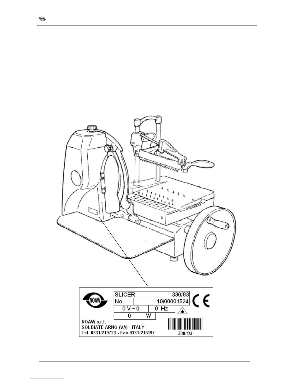
The follow ng plate s nstalled on the mach ne:
- manufacturer’s dent f cat on plate, mach ne plate,
techn cal data plate; placed on the base, as shown
n the f gure.
Installation, use and maintenance
5
3.
3. 3.
3. TECHNICAL CHARACERISTICS
TECHNICAL CHARACERISTICSTECHNICAL CHARACERISTICS
TECHNICAL CHARACERISTICS
3.1
3.13.1
3.1
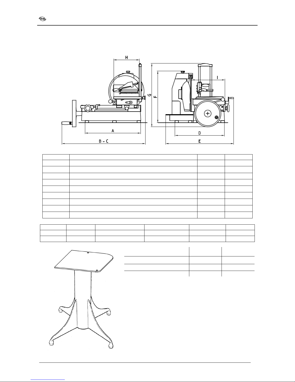
OVERAL SIZE
OVERAL SIZEOVERAL SIZE
OVERAL SIZE
R f.
R f.R f.
R f.
D
DD
D
eta ls
eta lseta ls
eta ls
330/83
330/83330/83
330/83
370/85
370/85370/85
370/85
A Feet d stance 570 630
B D stance beg nn ng carr age movement/blade cover 830 895
C Max. d stance beg nn ng/end movement 830 895
D Feet d stance 400 490
E Max. w dth d stance 650 740
F He ght 540 590
G Max. he ght d stance 710 720
H Table lenght 290 290
I Table w dth 330 370
Mod.
Mod.Mod.
Mod.
Blade
BladeBlade
Blade
Carr age movement
Carr age movementCarr age movement
Carr age movement
Th ckness adjuster
Th ckness adjusterTh ckness adjuster
Th ckness adjuster
Cut’s capac ty
Cut’s capac tyCut’s capac ty
Cut’s capac ty
Net we ght
Net we ghtNet we ght
Net we ght
330/83
ø mm 33
0
mm 280
mm 0
-
3
mm 190x290
kg 62
370/85
ø mm 370
mm 315
mm 0
-
4
mm 235x280
kg 88
Iron support column
Iron support columnIron support column
Iron support column:
::
: 330/83
330/83330/83
330/83
370/85
370/85370/85
370/85
He ght 820 mm 820 mm
Base 670x650 mm
670x760 mm
We ght
34 kg
34 kg
Furn shed tems and accessor es
Furn shed tems and accessor esFurn shed tems and accessor es
Furn shed tems and accessor es
The follow ng documents and accessor es are suppl ed w th the
mach ne, unless otherw se requested:
-Instruct on manual for nstallat on, use and ma ntenance;
-Guarantee cert f cate;
-Accessor es: lubr cat ng o l for carr age gu de bars.
Installation, use and maintenance
6
3.
3.3.
3.2
22
2
PROD
PRODPROD
PRODUCT THAT CAN BE SLIC
UCT THAT CAN BE SLICUCT THAT CAN BE SLIC
UCT THAT CAN BE SLICED
EDED
ED
The follow ng are products that can be sl ced:
-All types of cold cuts (cooked, raw, smoked);
-Boneless meat (cooked or raw at a temperature
of no lower than +3 °C);
-Bread and cheeses (those that can be sl ced,
such as Gruyere, Font na, etc.).
3.
3.3.
3.3
33
3
PRODUCT THAT CANNOT BE SLICED
PRODUCT THAT CANNOT BE SLICEDPRODUCT THAT CANNOT BE SLICED
PRODUCT THAT CANNOT BE SLICED
The follow ng are products that cannot be sl ced
because they could cause damage to people and
equ pment:
-Frozen foods;
-Deep-frozen foods;
-Food w th bones (meat and f sh);
-Vegetables;
-Any other product that could be sl ced but not
meant for consumpt on.
ATTENTION: Do not try to sl ce products that are not
ATTENTION: Do not try to sl ce products that are notATTENTION: Do not try to sl ce products that are not
ATTENTION: Do not try to sl ce products that are not
allowed.
allowed.allowed.
allowed.
4. DE
4. DE4. DE
4. DESCR
SCRSCR
SCRIPTION
IPTIONIPTION
IPTION
4.1
4.1 4.1
4.1 UNPACKING
UNPACKINGUNPACKING
UNPACKING
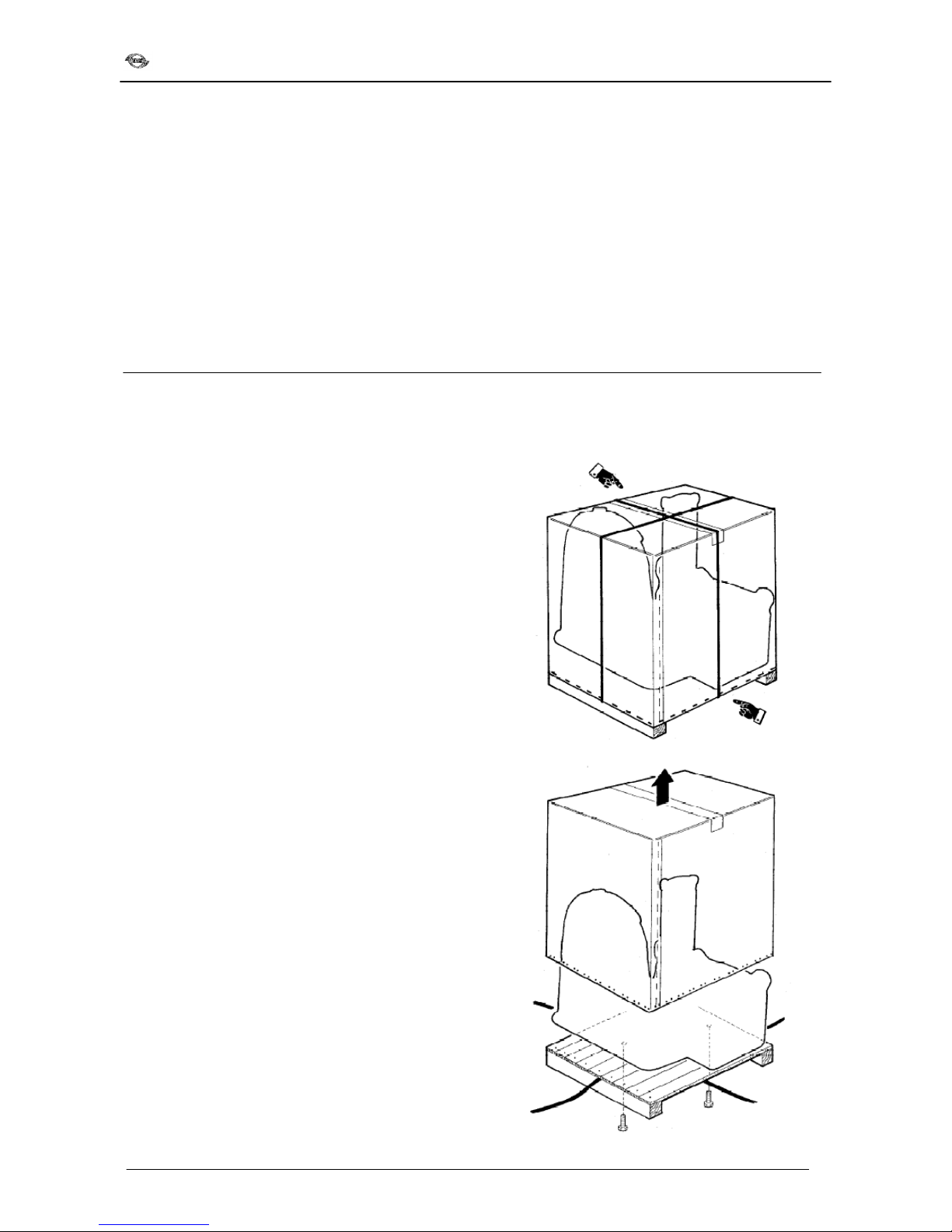
Check that the packag ng s unopened and
undamaged; otherw se, mmed ately nform the
forward ng agent or the area agent.
To take the mach ne out of the packag ng proceed as
follows:
-Cut and remove the plast c straps;
-Cut the cardboard box at the base wh ch s
attached to the pallet;
-L ft and remove the cardboard box; take out the
polythene bags w th the mach ne flywheel and
rubber feet;
-Loosen and remove the two screws that attach
the mach ne to the pallet;
Installation, use and maintenance
7
Supply of mach ne only:
Supply of mach ne only:Supply of mach ne only:
Supply of mach ne only:
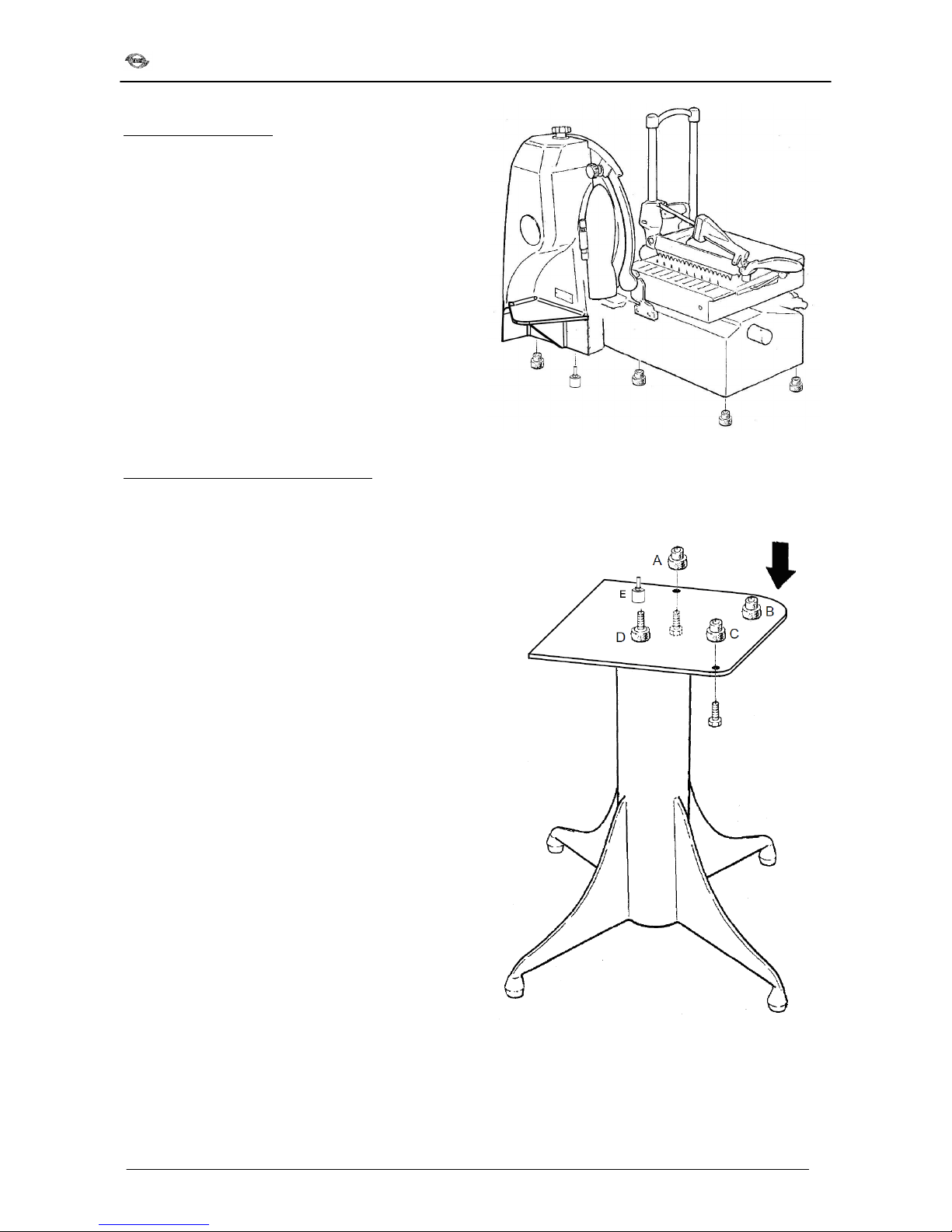
-L ft the mach ne carefully and nsert the four
s m lar rubber feet n the lodg ngs n the base.
-Put under the head of the mach ne the other foot
(d fferent from the rubber feet) screw ng t n the
lodg ng n the head.
-Put the mach ne n ts place of nstallat on.
Supply of mach ne and support column
Supply of mach ne and support columnSupply of mach ne and support column
Supply of mach ne and support column:
::
:
L ft the mach ne carefully and pay attent on to nsert
the rubber holed feet n order to have the same shape
of the pedestal plate (marked w th the arrow) w th the
same shape of the mach ne.
The mach ne s furn shed w th two rubber holed feet ( A
and C), one rubber foot B, a reg ster ng foot M12 D and
a l ttle reg ster ng foot E.
Place the mach ne on the support column try ng to put
the holed rubber feet n correspondence of the holes on
the plate.
Check that the mach ne s correctly settled on the
column by us ng the reg ster ng screws n the D
pos t on and the l ttle reg ster ng foot E, then lock the
mach ne n place by nsert ng the screw n the holed
feet, do not t ghten t too much.
El m nate all the packag ng (straps, cardboard,
polyurethane foam or polystyrene, polyethylene bags,
etc.)
WARNING
WARNINGWARNING
WARNING: The packag ng components (plast c straps,
cardboard, polyurethane foam) can be thrown away
w th
normal sol d wastes and therefore there s no d ff culty
n d spos ng of them.
However t s adv sable to d spose of products
separately (d fferent al collect ng) n conform ty w th
the regulat ons n force for adequate recycl ng.
DO NOT DISCARD THE PACKAGING PRODUCTS IN THE
DO NOT DISCARD THE PACKAGING PRODUCTS IN THE DO NOT DISCARD THE PACKAGING PRODUCTS IN THE
DO NOT DISCARD THE PACKAGING PRODUCTS IN THE
ENVIRONMENT!
ENVIRONMENT!ENVIRONMENT!
ENVIRONMENT!
Installation, use and maintenance
8
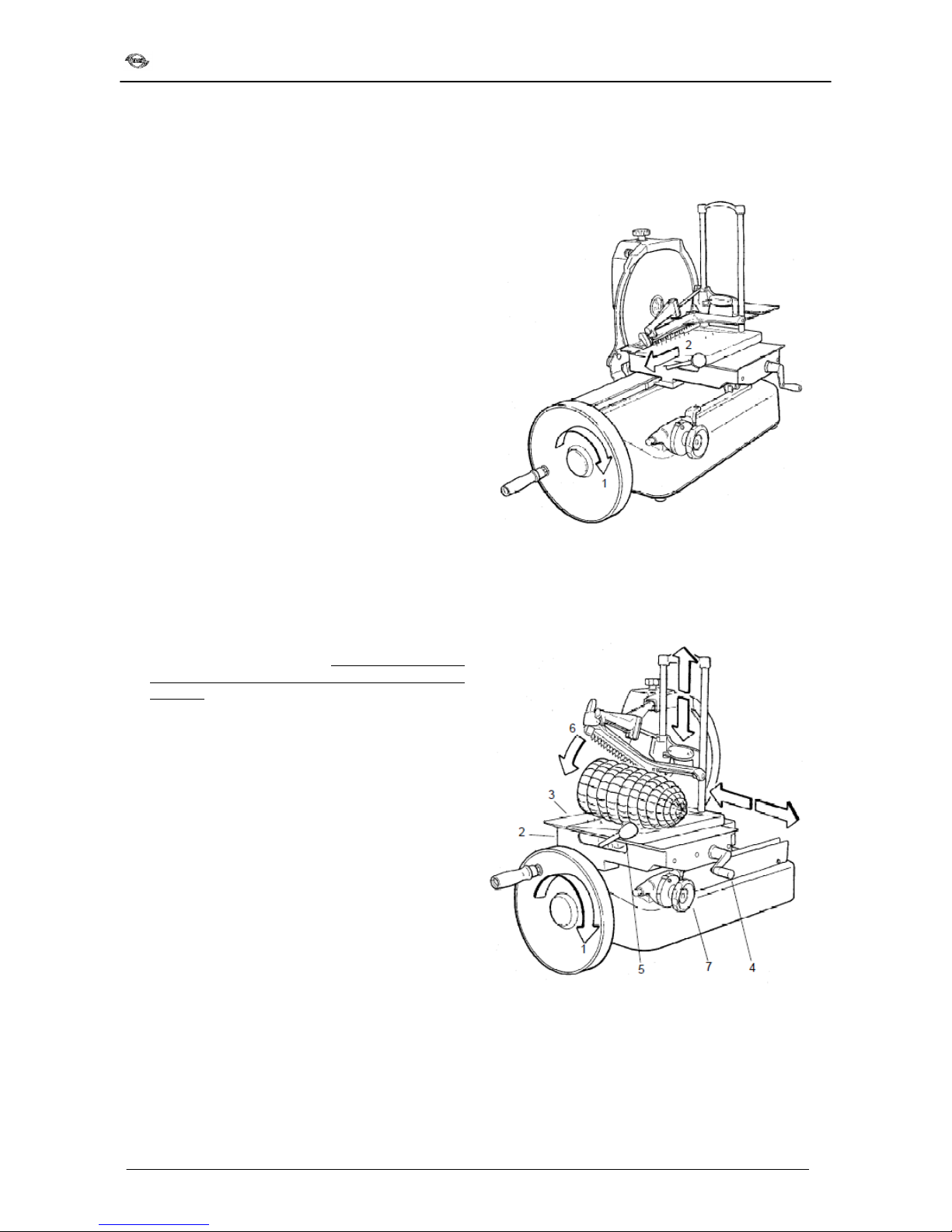
Assembly of the flywheel
Assembly of the flywheelAssembly of the flywheel
Assembly of the flywheel
:
::
:
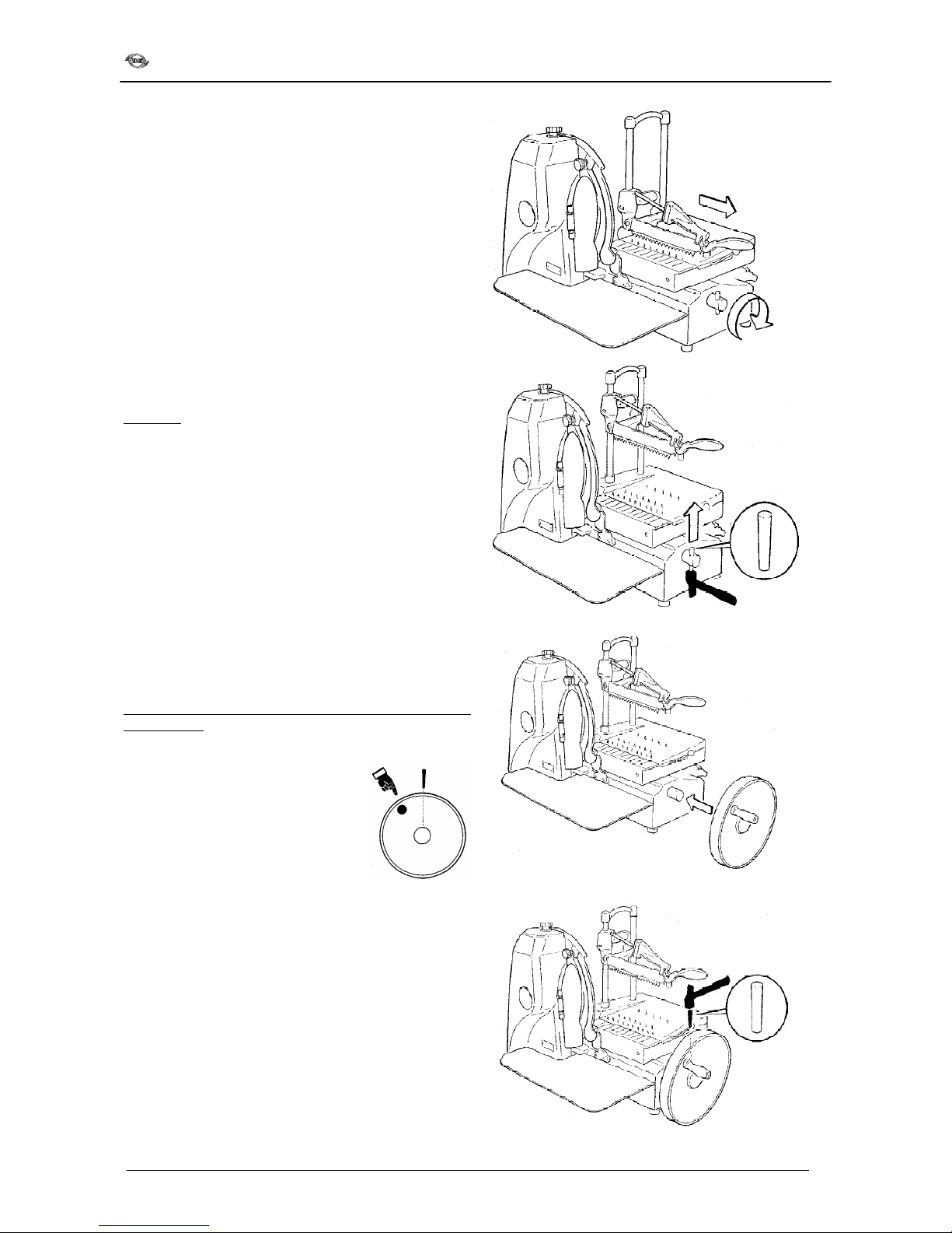
Move the mach ne carr age all the way towards the
operator.
Take out the taper p n from the flywheel shaft.
Atten
AttenAtten
Attent on
t ont on
t on:
::
:
hammer the p n at the tapered end (smaller d ameter).
Insert the flywheel so that the manoeuvr ng handle s
at the top and to the left, as shown n the f gure,
compared to the hole for the taper p n.
Check the correct correspondence of the flywheel shaft
sleeve holes.
Insert the p n nto the sleeve as shown n the f gure
w th the tapered end (smaller d ameter) towards the
sleeve tself.
Hammer the oppos te end of the p n (larger d ameter)
nsert ng t all the way.
Installation, use and maintenance
9
4.2
4.2 4.2
4.2 MAIN COMPONENTS
MAIN COMPONENTSMAIN COMPONENTS
MAIN COMPONENTS
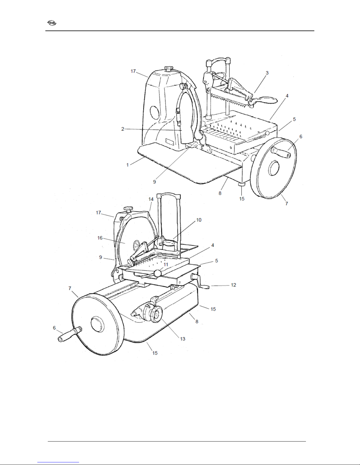
1.
Food plate
2. Sl ce deflector
3. Hand gr p
4. Sl d ng overplate
5. Carr age
6. Flywheel manouevr ng handle
7. Flywheel
8. Base
9.
Blade protect on
10. Vert cal sl d ng food press
11. Rap d overplate advance lever (Mod. 370/85)
12. Handwheel overplate advance
13. Regulat ng knob for sl ce th ckness
14. Blade cover
15. Foot
16. Blade
17. Sharpener

Installation, use and maintenance
10
4.3
4.3 4.3
4.3 GENERAL DESCRIPTION
GENERAL DESCRIPTIONGENERAL DESCRIPTION
GENERAL DESCRIPTION
The sl c ng mach ne has been des gned and made
to offer max mum safety when n use, dur ng
clean ng and ord nary ma ntenance; max mum
hyg ene from the use of nox d sable mater als or
adequately protected aga nst ox d sat on together
w th an attent ve des gn of all the parts that come
nto contact w th food; max mum cutt ng prec s on
and capac ty together w th sturd ness and rel ab l ty
of the structure.
The mach ne s essent ally made up of a base that
holds a c rcular blade that s vert cally mounted and
a sl d ng carr age on bars, parallel to the cutt ng
edge of the blade, wh ch n turn holds a food plate.
The food plate s made up of a base plate and an
overplate wh ch sl des at r ght angles to the edge of
the blade for sl c ng the food; the overplate also has
an appropr ate selfstopp ng dev ce, wh ch can be
regulated n he ght, to keep the product n ts proper
place dur ng cutt ng operat ons (food press).
Carr age movement and blade rotat on are
completely manual; by act vat ng rotat on of the
flywheel w th the spec al handle the carr age s put
nto mot on and at the same t me w th a cha n
transm ss on the blade s turned.
The product s cut dur ng the forward movement of
the carr age, parallel to the blade; the th ckness of
the sl ce s regulated by a mechan cal dev ce wh ch
s automat cally started every t me the carr age
comes back, mak ng the sl d ng overplate
transversally towards the blade, w th a value wh ch
s pre-determ ned by the graduated handwheel.
All the components of the mach ne are made of a
l ght alum n um alloy, n sta nless steel and plast c
for food products as accord ng to the san tary
regulat ons n force.
The mach ne has a sharpener wh ch s extremely
easy and safe to use.
The food plate, sharpener and blade cover can be
removed for clean ng.
4.3.1
4.3.1 4.3.1
4.3.1 R sks dur ng use
R sks dur ng useR sks dur ng use
R sks dur ng use
DO NOT use the mach ne f you are not n p
DO NOT use the mach ne f you are not n pDO NOT use the mach ne f you are not n p
DO NOT use the mach ne f you are not n perfect
erfecterfect
erfect
psycho
psychopsycho
psycho-
--
-phys cal cond t on and DO NOT let anyone
phys cal cond t on and DO NOT let anyonephys cal cond t on and DO NOT let anyone
phys cal cond t on and DO NOT let anyone
come near dur ng use; concentrate when load ng
come near dur ng use; concentrate when load ng come near dur ng use; concentrate when load ng
come near dur ng use; concentrate when load ng
and
andand
and
cutt ng the product.
cutt ng the product.cutt ng the product.
cutt ng the product.
P
PP
Pay attent on!
ay attent on!ay attent on!
ay attent on!
Only cut products wh ch are allowed; DO NOT try
Only cut products wh ch are allowed; DO NOT tryOnly cut products wh ch are allowed; DO NOT try
Only cut products wh ch are allowed; DO NOT try
cutt ng products wh ch are forb dden
cutt ng products wh ch are forb ddencutt ng products wh ch are forb dden
cutt ng products wh ch are forb dden.
..
.
DURING CLEANING, LUBRICATI
DURING CLEANING, LUBRICATIDURING CLEANING, LUBRICATI
DURING CLEANING, LUBRICATION AND BLADE
ON AND BLADE ON AND BLADE
ON AND BLADE
SHARPENING ALWAYS USE PROTECTIVE GLOVES
SHARPENING ALWAYS USE PROTECTIVE GLOVES SHARPENING ALWAYS USE PROTECTIVE GLOVES
SHARPENING ALWAYS USE PROTECTIVE GLOVES
WHICH ARE RESISTANT TO CUTS AND TEARS
WHICH ARE RESISTANT TO CUTS AND TEARSWHICH ARE RESISTANT TO CUTS AND TEARS
WHICH ARE RESISTANT TO CUTS AND TEARS.
..
.
Installation, use and maintenance
11
5.
5.5.
5.
INSTALLATION
INSTALLATIONINSTALLATION
INSTALLATION
5.1
5.1 5.1
5.1 INSTALLATION OF THE MACHINE
INSTALLATION OF THE MACHINEINSTALLATION OF THE MACHINE
INSTALLATION OF THE MACHINE
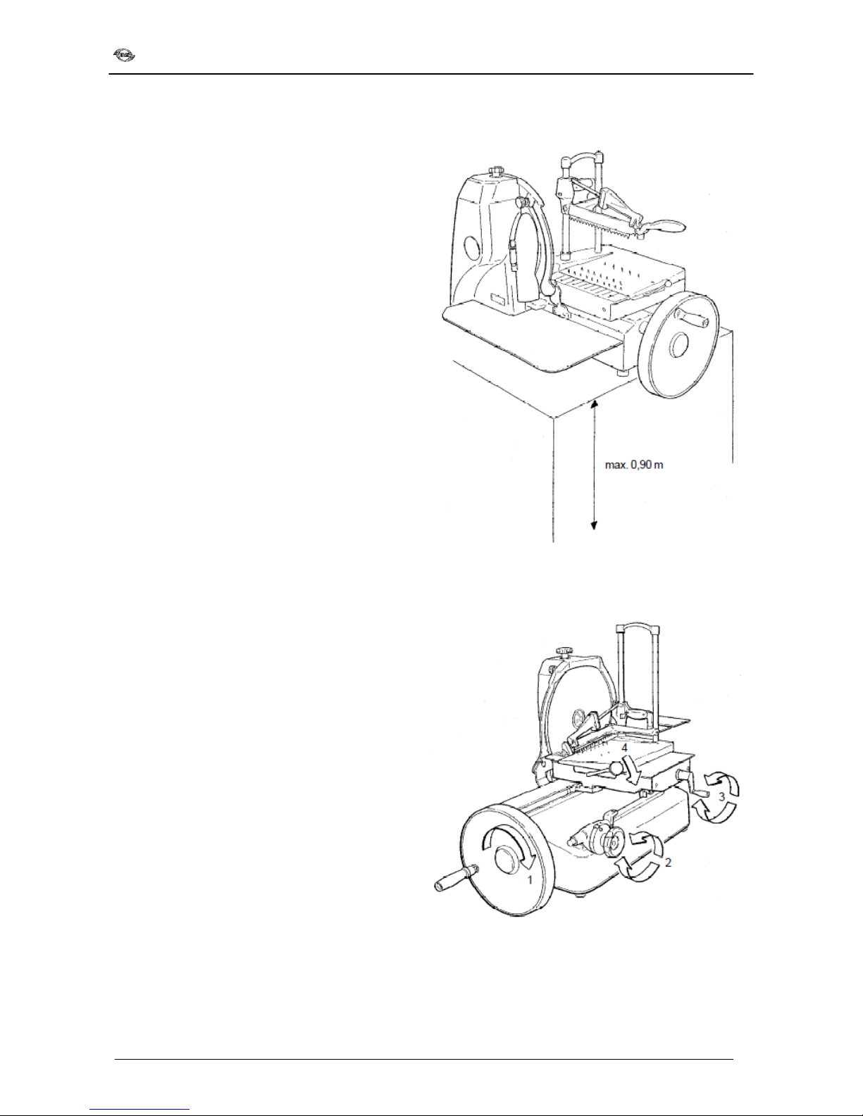
If a support column (opt onal) s not used, nstall the
mach ne on a surface wh ch s level, dry and su table
for the we ght of the mach ne plus the food to be
sl ced; refer to paragraph 3.1
Check that there s noth ng that can get n the way of
the flywheel, carr age movement and food load ng.
5.2
5.2 5.2
5.2 COMMAND DESCRIPTION
COMMAND DESCRIPTIONCOMMAND DESCRIPTION
COMMAND DESCRIPTION
5.2.1
5.2.1 5.2.1
5.2.1
MANOEUVRING FLYWHEEL
MANOEUVRING FLYWHEELMANOEUVRING FLYWHEEL
MANOEUVRING FLYWHEEL
The flywheel (1) turned clockw se allows the carr age
to be moved w th the food plate w th s multaneous
blade rotat on.
5.2.2 REGULATING KNOB FOR SLICE THICKNESS
5.2.2 REGULATING KNOB FOR SLICE THICKNESS5.2.2 REGULATING KNOB FOR SLICE THICKNESS
5.2.2 REGULATING KNOB FOR SLICE THICKNESS
The th ckness of the sl ce s regulated by turn ng the
graduated scale knob (2) clockw se.
Regulat ng f eld: see paragraph 3.2.
5.2.3 OVERPLATE ADVANCE HANDWHEEL
5.2.3 OVERPLATE ADVANCE HANDWHEEL5.2.3 OVERPLATE ADVANCE HANDWHEEL
5.2.3 OVERPLATE ADVANCE HANDWHEEL
The handwheel (3) allows the overplate w th the
product to be brought qu ckly near to the blade after
load ng t or taken away from the blade after cutt ng
or for small regulat ons.
5.2.4 OVERPLAT
5.2.4 OVERPLAT5.2.4 OVERPLAT
5.2.4 OVERPLATE RAPID ADVANCE LEVER
E RAPID ADVANCE LEVERE RAPID ADVANCE LEVER
E RAPID ADVANCE LEVER
By mov ng t downwards and keep ng t there, the
lever (4), only for model 370/85, allows rap d
movement of the overplate, towards the blade or
away from t after cutt ng.
Th s operat on s much qu cker than w th the
handwheel (3).
Installation, use and maintenance
12
6.
6. 6.
6. USING THE SLICING MACHINE
USING THE SLICING MACHINEUSING THE SLICING MACHINE
USING THE SLICING MACHINE
6.1
6.1 6.1
6.1 LOADING THE GOODS
LOADING THE GOODSLOADING THE GOODS
LOADING THE GOODS
-Us ng the flywheel (1) br ng the carr age (2) all
forward (towards the operator).
-Pull back the sl d ng overplate (3) completely
(away from the blade) us ng the handwheel (4) or
the rap d advance lever (5).
-Place the food to be sl ced on the overplate and
block t w th the food press (6) regulat ng the
he ght as well.
-Regulate the th ckness of the sl ce by pull ng and
rotat ng the knob (7) at the same t me, graduated
from 0 to 16.
-Br ng the overplate w th the goods towards the
blade by us ng the rap d advance lever or the
handwheel.
6.2
6.2 6.2
6.2 CUTTING THE GOODS
CUTTING THE GOODSCUTTING THE GOODS
CUTTING THE GOODS
-Turn the flywheel clockw se (do not turn t counter
clockw se, th s could ser ously damage the
mach ne).
-Dur ng the forward movement of the carr age
(away from the operator) the goods w ll go nto
the blade and the sl ce, gu ded by the sl ce
deflector, w ll fall onto the plate below.
-Dur ng the return movement of the carr age
(towards the operator) the mechan cal dev ce
wh ch makes the overplate advance transversally
towards the blade w ll be put nto mot on, ts value
pre-determ ned w th the sl ce th ckness regulat ng
knob.
Installation, use and maintenance
13
6.3
6.3 6.3
6.3 CLEANING THE SLICING MACHINE
CLEANING THE SLICING MACHINECLEANING THE SLICING MACHINE
CLEANING THE SLICING MACHINE
6.3.1
6.3.1 6.3.1
6.3.1 GENERAL INFORMATION
GENERAL INFORMATIONGENERAL INFORMATION
GENERAL INFORMATION
The mach nes must be properly cleaned at least once
a day, f necessary even more.
If the mach nes have not been used for a wh le they
must be cleaned before use as well..
WARNING: Danger of cutt ng!
WARNING: Danger of cutt ng!WARNING: Danger of cutt ng!
WARNING: Danger of cutt ng!
Use protect ve gloves wh ch are res stant to cutt ng
Use protect ve gloves wh ch are res stant to cutt ngUse protect ve gloves wh ch are res stant to cutt ng
Use protect ve gloves wh ch are res stant to cutt ng
and tear ng and concentrate on the job at hand.
and tear ng and concentrate on the job at hand.and tear ng and concentrate on the job at hand.
and tear ng and concentrate on the job at hand.
PAY CAREFUL ATTENTION!
PAY CAREFUL ATTENTION!PAY CAREFUL ATTENTION!
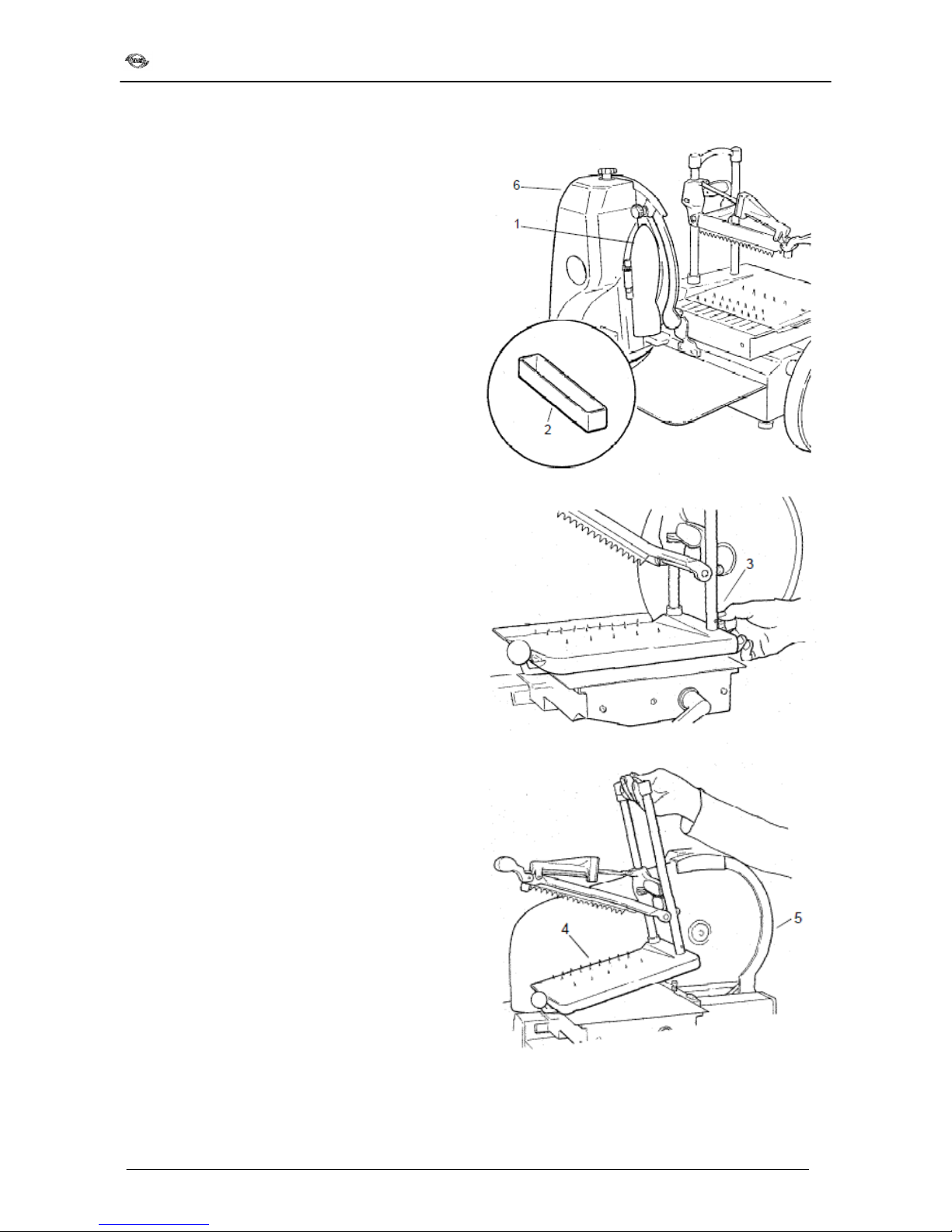
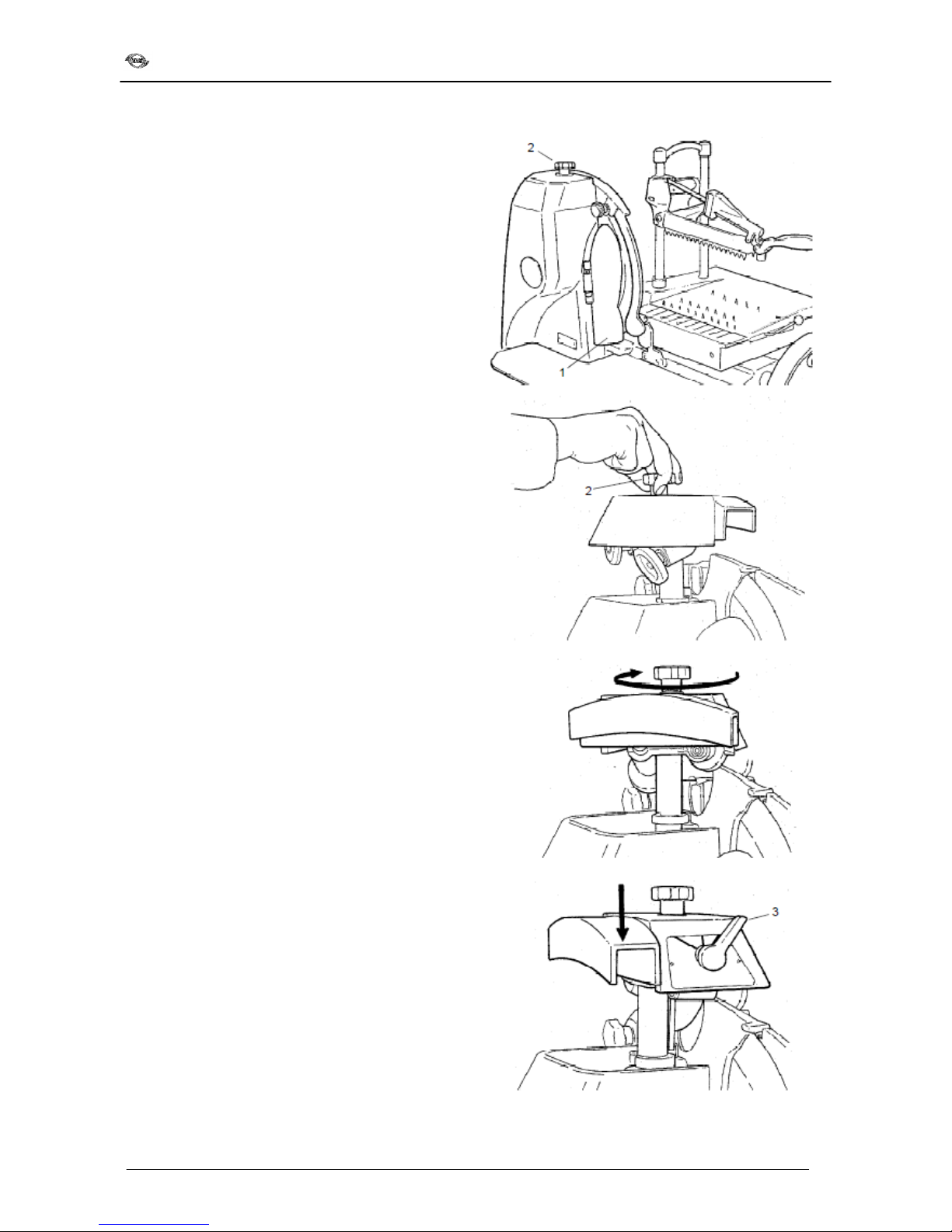
PAY CAREFUL ATTENTION!
-Open the sl ce deflector (1);
-Take out the conta ner (2);
-Loosen the knob (3) and l ft the sl d ng overplate
(4) w th ts food press arm;
-Remove the blade cover (5);
-Remove the sharpener (6), ra se t us ng the knob
on the top.
Clean all the d sassembled parts, the mach ne body,
etc. only us ng hot water and a b odegradable foam ng
detergent for d shes at a temperature of no lower than
+30 °C us ng a soft, spongy cloth and a nylon brush f
necessary for the plate and the sharp food press.
R nse well w th a lot of hot clean water only and dry
w th a soft cloth or a spongy mater al
WARNING: DO NOT clean the mach ne w th jets of
WARNING: DO NOT clean the mach ne w th jets ofWARNING: DO NOT clean the mach ne w th jets of
WARNING: DO NOT clean the mach ne w th jets of
water or steam or s m lar.
water or steam or s m lar.water or steam or s m lar.
water or steam or s m lar.

Installation, use and maintenance
14
7.
7. 7.
7. MAINTENANCE AND REPAIRS
MAINTENANCE AND REPAIRSMAINTENANCE AND REPAIRS
MAINTENANCE AND REPAIRS
7.1
7.1 7.1
7.1 GENERAL INFORMATION
GENERAL INFORMATIONGENERAL INFORMATION
GENERAL INFORMATION
The operator s allowed to carry out the follow ng
ma ntenance:
-Blade sharpen ng
Blade sharpen ngBlade sharpen ng
Blade sharpen ng, per od cally; the nterval and
length of the sharpen ng obv ously depend on
the use of the mach ne (work t mes and type of
product used).
-Lubr cat on of the carr age gu de bars
Lubr cat on of the carr age gu de barsLubr cat on of the carr age gu de bars
Lubr cat on of the carr age gu de bars
an
an an
an
overplate
overplateoverplate
overplate: weekly;
-Adjustment of the blade drive chain: as
necessary, see the relative paragraph;
-Adjustment of the bevel gear pa r
Adjustment of the bevel gear pa rAdjustment of the bevel gear pa r
Adjustment of the bevel gear pa r: as
necessary, see the relat ve paragraph.
Ma ntenance to be carr ed out exclus vely by
personnel author sed by the manufacturer s as
follows:
-
--
-
Replac ng the blade;
Replac ng the blade;Replac ng the blade;
Replac ng the blade;
-
--
-
Replac ng the sharpener gr ndstones;
Replac ng the sharpener gr ndstones;Replac ng the sharpener gr ndstones;
Replac ng the sharpener gr ndstones;
-
--
-
Replac ng the cha n;
Replac ng the cha n;Replac ng the cha n;
Replac ng the cha n;
-
--
-
Repa r ng the structural parts
Repa r ng the structural partsRepa r ng the structural parts
Repa r ng the structural parts, repa r ng and/or
replac ng components under the base.
Installation, use and maintenance
15
7.2
7.2 7.2
7.2 SHARPENING THE BLADE
SHARPENING THE BLADESHARPENING THE BLADE
SHARPENING THE BLADE
Proceed as follows as so
on as t s not ced that there
s
less cutt ng capac ty::
WARNING: Danger of cutt ng!
WARNING: Danger of cutt ng!WARNING: Danger of cutt ng!
WARNING: Danger of cutt ng!
Use protect ve gloves wh ch are res stant to cutt ng
Use protect ve gloves wh ch are res stant to cutt ngUse protect ve gloves wh ch are res stant to cutt ng
Use protect ve gloves wh ch are res stant to cutt ng
and tear ng and concentrate on the job at hand.
and tear ng and concentrate on the job at hand.and tear ng and concentrate on the job at hand.
and tear ng and concentrate on the job at hand.
PAY CAREFUL ATTENTION!
PAY CAREFUL ATTENTION!PAY CAREFUL ATTENTION!
PAY CAREFUL ATTENTION!
-Open the sl ce deflector (1);
-Clean the blade w th denatured alcohol or hot
water;
-W th the knob (2) ra se the cover of the sharpener,
turn t 180° and lower t aga n;
-Start the mach ne (only blade rotat on);
-Move the lever (3) from the “0”
“0” “0”
“0” pos t on to the
“sharpen ng”
“sharpen ng” “sharpen ng”
“sharpen ng” pos t on and hold t n th s pos t on
for 10-15 seconds;
-Move the lever (3) to the “burr”
“burr” “burr”
“burr” pos t on for 2-3
seconds to remove the sharpen ng burr;
-Put the lever back to the “0”
“0” “0”
“0” pos t on and stop the
blade movement;
-Ra se the cover aga n, turn t 180° and put t back
to ts or g nal pos t on;
-Clean the blade and the mach ne
Note: do not ns st more than 2
Note: do not ns st more than 2Note: do not ns st more than 2
Note: do not ns st more than 2-
--
-3 seconds w th the
3 seconds w th the3 seconds w th the
3 seconds w th the
burr ng operat on so as to avo d damage to the edge
burr ng operat on so as to avo d damage to the edgeburr ng operat on so as to avo d damage to the edge
burr ng operat on so as to avo d damage to the edge
of the blade
of the bladeof the blade
of the blade.
..
.
Installation, use and maintenance
16
7.3
7.3 7.3
7.3 LUBRICATING THE GUIDE BARS OF THE
LUBRICATING THE GUIDE BARS OF THELUBRICATING THE GUIDE BARS OF THE
LUBRICATING THE GUIDE BARS OF THE
CARRIAGE
CARRIAGECARRIAGE
CARRIAGE
AND OVERPLATE
AND OVERPLATEAND OVERPLATE
AND OVERPLATE
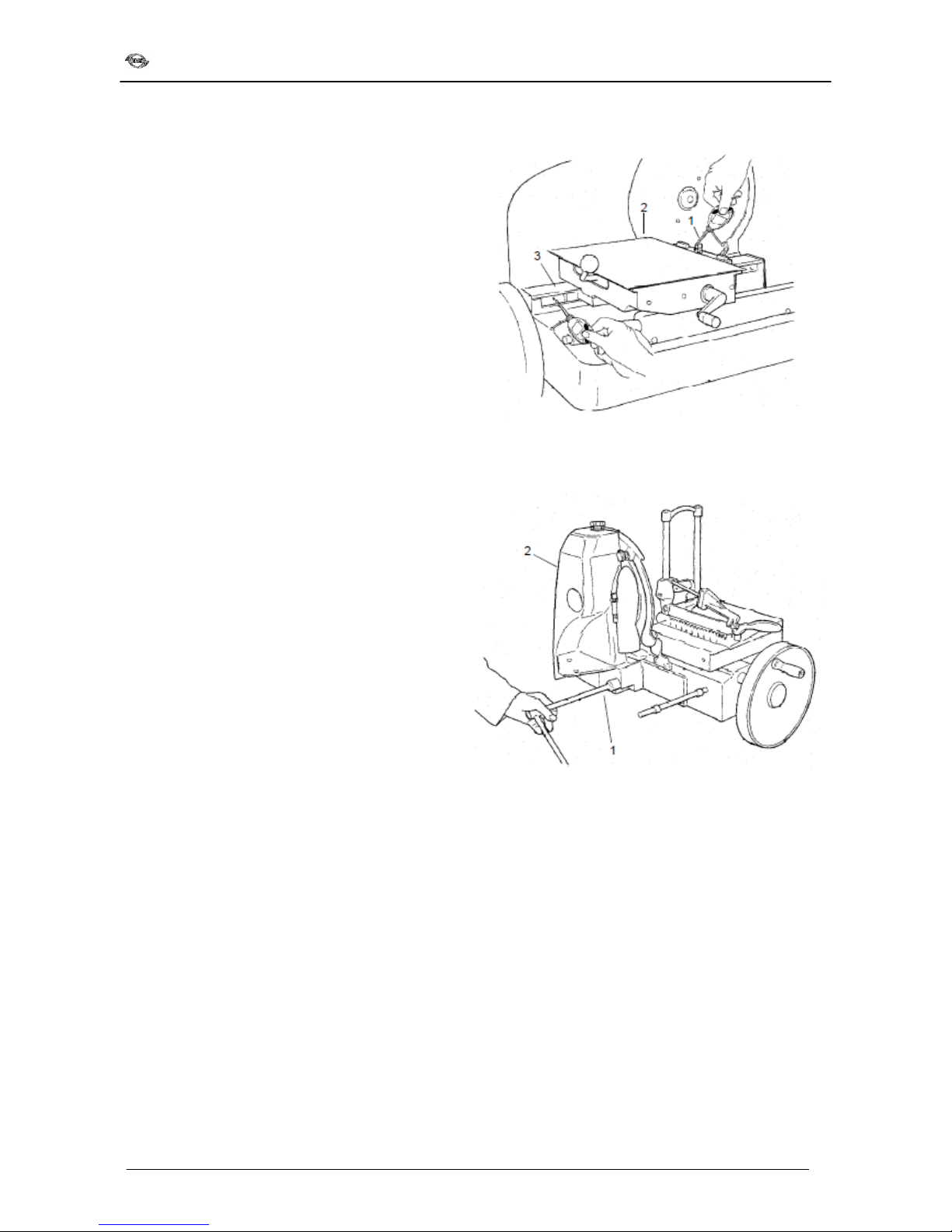
-After each clean ng operat on of the mach ne put
a few drops of o l n the hole (1) of the plate (2);
-Put a few drops of o l along the sl d ng bar (3) of
the carr age;
-Turn the flywheel br efly.
Note: Only use wh te Vasel ne o l. Do not use
Note: Only use wh te Vasel ne o l. Do not use Note: Only use wh te Vasel ne o l. Do not use
Note: Only use wh te Vasel ne o l. Do not use
vegetable o ls
vegetable o lsvegetable o ls
vegetable o ls.
..
.
7.4
7.47.4
7.4
ADJU
ADJUADJU
ADJUSTING THE
STING THE STING THE
STING THE CHAIN
CHAINCHAIN
CHAIN
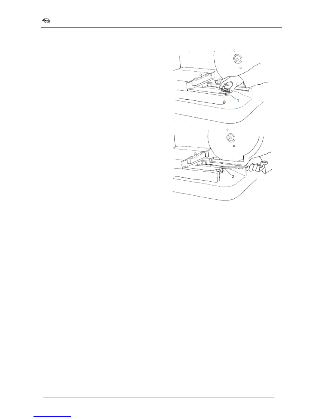
If you should hear a t ck ng no se when us ng the
mach ne check the tens on of the blade cha n as
follows:
-Loosen the two nuts (1) wh ch hold the head (2);
-Ra se the head (2) unt l the requ red tens on of
the cha n s obta ned;
-T ghten the nuts and check.
Installation, use and maintenance
17
7.5
7.5 7.5
7.5 ADJUSTING THE BEVEL GEAR PAIR
ADJUSTING THE BEVEL GEAR PAIRADJUSTING THE BEVEL GEAR PAIR
ADJUSTING THE BEVEL GEAR PAIR
If there s too much play n the flywheel at the start of
rotat on proceed as follows to el m nate t:
-
Remove the cover (1) us ng a screwdr ver;
-T ghten the nut (2) unt l all play s el m nated;
-- Replace the cap (1).
8.
8. 8.
8. DISMANTLING THE SLICING MACHINE
DISMANTLING THE SLICING MACHINEDISMANTLING THE SLICING MACHINE
DISMANTLING THE SLICING MACHINE
The mach nes are made up of:
- Alum n um alloy structure;
- Insert ons and var ous n sta nless steel;
- Electr c parts and w res, etc.;
- Electr c motor;
- Plast c mater als, etc.
If d sassembly and d smantl ng are to be carr ed out
by a th rd party, only consult f rms that are
author sed n the demol t on of the above
ment oned mater als.
If you carry out the d smantl ng yourself the
mater als must be separated accord ng to type and
consult a spec al sed f rm for the r d sposal.
Always ab de by the regulat ons n force n your
country.
WARNING: In any case t s necessary to consult the
WARNING: In any case t s necessary to consult theWARNING: In any case t s necessary to consult the
WARNING: In any case t s necessary to consult the
manufacturer or qual f ed personnel author sed by
manufacturer or qual f ed personnel author sed by manufacturer or qual f ed personnel author sed by
manufacturer or qual f ed personnel author sed by
the
thethe
the
manufacturer for the removal of the c rc
manufacturer for the removal of the c rcmanufacturer for the removal of the c rc
manufacturer for the removal of the c rcular
ular ular
ular
blade and
blade andblade and
blade and
subsequent removal of the cutt ng w re
subsequent removal of the cutt ng w re subsequent removal of the cutt ng w re
subsequent removal of the cutt ng w re
so that t can
so that t canso that t can
so that t can
be d sposed of safely.
be d sposed of safely.be d sposed of safely.
be d sposed of safely.
DO NOT ABANDON SCRAPS WHERE THERE IS FREE
DO NOT ABANDON SCRAPS WHERE THERE IS FREEDO NOT ABANDON SCRAPS WHERE THERE IS FREE
DO NOT ABANDON SCRAPS WHERE THERE IS FREE
ACCESS (THERE SHOULD BE BARRIERS AND SIGNS)
ACCESS (THERE SHOULD BE BARRIERS AND SIGNS)ACCESS (THERE SHOULD BE BARRIERS AND SIGNS)
ACCESS (THERE SHOULD BE BARRIERS AND SIGNS)
BECAUSE THIS CAN BE VERY DANGEROUS FOR
BECAUSE THIS CAN BE VERY DANGEROUS FORBECAUSE THIS CAN BE VERY DANGEROUS FOR
BECAUSE THIS CAN BE VERY DANGEROUS FOR
PEOPLE, SPECIALLY CHILDREN AND ANIMAL
PEOPLE, SPECIALLY CHILDREN AND ANIMALPEOPLE, SPECIALLY CHILDREN AND ANIMAL
PEOPLE, SPECIALLY CHILDREN AND ANIMALS; THE
S; THES; THE
S; THE
OWNER HAS SOLE RESPONSIBILITY
OWNER HAS SOLE RESPONSIBILITYOWNER HAS SOLE RESPONSIBILITY
OWNER HAS SOLE RESPONSIBILITY.
..
.

Noaw s.r.l
V a Colombera, 27
21048 Solb ate Arno (VA) – Italy
Tel. 0331.219.723 - Fax 0331.216.197
E-ma l: noaw@noaw. t
http://www.noaw. t - www.noawsrl.com
This manual suits for next models
1
Table of contents
Other Noaw Kitchen Appliance manuals

Noaw
Noaw NS220 Specification sheet

Noaw
Noaw LEADER 350G/LI Specification sheet

Noaw
Noaw NS300M Troubleshooting guide

Noaw
Noaw 300/10H Troubleshooting guide

Noaw
Noaw TWS Service manual

Noaw
Noaw NS220 User manual

Noaw
Noaw 250/14 Troubleshooting guide

Noaw
Noaw A300 Specification sheet

Noaw
Noaw NS350HDA Specification sheet

Noaw
Noaw 30E Specification sheet


